2004 CHRYSLER VOYAGER transmission
[x] Cancel search: transmissionPage 34 of 2585

Kilometers 120 000 125 000 130 000 134 000 139 000 144 000
(Miles) (75,000) (78,000) (81,000) (84,000) (87,000) (90,000)
Change engine oil and engine
oil filter.XXXXX X
Inspect the brake linings. X X
Inspect the engine air cleaner
filter, replace if necessary. *XXXX
Replace theengine air
cleaner filterXX
Replace thespark plugson
3.3 liter engines.X
Replace theignition cables
on 3.3 liter engines.X
Replace thespark plugson
2.4 liter engines.X
Inspect and adjust the power
steering pump belt tension on
2.4 liter engines.XX
Inspect the generator belt on
2.4 liter engines, replace if
necessary.XX
Inspect the tie rod ends and
boot seals.X
Inspect engine accessory
drive belts on 3.3 liter
engines, replace if necessary.
³XX
Change the manual
transmission fluid.X
Check thePCV valveand
replace if necessary. Not
required if previously
changed.*X
Change the All Wheel Drive
power transfer unit fluid. (See
the note at the end of this
chart.)XX
Change the All Wheel Drive
(AWD) overrunning clutch and
rear carrier fluid. (See note at
the end of this chart)X
Replace theengine timing
belton 2.4 liter engines. *X
Replace the air conditioning
filter.XX
RSLUBRICATION & MAINTENANCE0-21
MAINTENANCE SCHEDULES (Continued)
Page 35 of 2585

Kilometers 149 000 154 000 158 000 160 000 163 000 168 000
(Miles) (93,000) (96,000) (99,000) (100,000) (102,000) (105,000)
Change engine oil and engine
oil filter.XXX X X
Inspect the brake linings. X
Inspect the engine air cleaner
filter, replace if necessary. *XXXXX
Replace theengine air
cleaner filter*X
Inspect and adjust the power
steering pump belt tension on
2.4 liter engines.X
Inspect the generator belt on
2.4 liter engines, replace if
necessary.X
Inspect engine accessory
drive belts on 3.3 liter
engines, replace if necessary.
³X
Change the manual
transmission fluid.X
Change the All Wheel Drive
(AWD) power transfer unit,
overrunning clutch and rear
carrier fluid. (See note at the
end of this chart)X
Flush and replace the engine
coolant at 60 months or
100,000 miles.X
Replace the air conditioning
filter.X
0 - 22 LUBRICATION & MAINTENANCERS
MAINTENANCE SCHEDULES (Continued)
Page 36 of 2585

Kilometers 173 000 178 000 182 000 187 000 192 000
(Miles) (108,000) (111,000) (114,000) (117,000) (120,000)
Change engine oil and engine oil filter. X X X X X
Inspect the brake linings. X X
Inspect the engine air cleaner filter, replace
if necessary. *XXXX
Replace theengine air cleaner filter.X
Replace thespark plugson 2.4 liter
engines.X
Replace theignition cableson 2.4 liter
engines.X
Inspect and adjust the power steering pump
belt tension on 2.4 liter engines.X
Inspect the generator belt on 2.4 liter
engines, replace if necessary.X
Inspect engine accessory drive belts on 3.3
liter engines, replace if necessary. ³X
Inspect the tie rod ends and boot seals. X
Inspect thePCV valveand replace as
necessary.*X
Change the automatic transmission fluid
and filter.X
Change the All Wheel Drive (AWD) power
transfer unit fluid. (See note at the end of
this chart)X
Replace the air conditioning filter.X
* This maintenance is recommended by the manu-
facture to the owner but is not required to maintain
the emissions warranty.
³ This maintenance is not required if previously
replaced.
Inspection and service should also be performed
anytime a malfunction is observed or suspected.
Retain all receipts.
NOTE: The AWD power transfer unit fluid and the
AWD overrunning clutch/ rear carrier fluid must bechanged at the intervals shown in schedule B if the
vehicle is operated under any of the conditions
noted by a diamond at the beginning of the sched-
ule.
WARNING: You can be badly injured working on or
around a motor vehicle. Do only that service work
for which you have the knowledge and the right
equipment. If you have any doubt about your ability
to perform a service job, take your vehicle to a
competent mechanic.
RSLUBRICATION & MAINTENANCE0-23
MAINTENANCE SCHEDULES (Continued)
Page 37 of 2585

DESCRIPTION ± DIESEL ENGINES ± EXPORT
There are two maintenance schedules that show
therequiredservice for your vehicle.
First is ScheduleªAº. It is for vehicles that are not
operated under any of the conditions listed under
Schedule9B9.
Second is ScheduleªBº. It is for vehicles that are
operated under the conditions that are listed below
and at the beginning of the schedule.
²Extensive engine idling.
²Driving in dusty conditions.
²More than 50% of your driving is at sustained
high speeds during hot weather, above 32É C (90É F).
²Trailer towing.
²Taxi, police, or delivery service (commercial ser-
vice).
NOTE: Most vehicles are operated under the condi-
tions listed for Schedule(B(.
Use the schedule that best describes your driving
conditions. Where time and mileage are listed, follow
the interval that occurs first.
CAUTION: Failure to perform the required mainte-
nance items may result in damage to the vehicle.
At Each Stop for Fuel
²Check the engine oil level about 5 minutes after
a fully warmed engine is shut off. Checking the oil
level while the vehicle is on level ground willimprove the accuracy of the oil level reading. Add oil
only when the level is at or below the ADD or MIN
mark.
²Check the windshield washer solvent and add if
required.
Once a Month
²Check the tire pressure and look for unusual
wear or damage.
²Inspect the battery and clean and tighten the
terminals as required.
²Check the fluid levels of coolant deaeration bot-
tle, brake master cylinder and transmission, add as
needed.
²Check all lights and all other electrical items for
correct operation.
At Each Oil Change
²Change the engine oil filter.
²Inspect the exhaust system.
²Inspect the brake hoses.
²Inspect the CV joints and front suspension com-
ponents.
²Check the manual transmission fluid level.
²Check the coolant level, hoses, and clamps.
²Inspect engine accessory drive belts. Replace as
necessary.
²Inspect for the presence of water in the fuel fil-
ter/water separator unit.
²Rotate the tires at each oil change interval (20
000 km).
SCHEDULE A - DIESEL ENGINES
Kilometers 20 000 km 40 000 km 60 000 km 80 000 km 100 000
km
Change engine oil and engine oil filter.XXXX X
Inspect engine air filter element. Replace as
necessary.XX X
Replace engine air filter element X X
Replace fuel filter/water separator unit.XXXX X
Inspect timing belt tensioner and replace if
necessary. ³X
Replace engine timing belt and idler
pulleys.X
Check front end alignment. X X
Inspect the tie rod ends and boot seals. X X
Inspect the brake linings.XXXX X
0 - 24 LUBRICATION & MAINTENANCERS
MAINTENANCE SCHEDULES (Continued)
Page 41 of 2585

WARNING: DO NOT ALLOW JUMPER CABLE
CLAMPS TO TOUCH EACH OTHER WHEN CON-
NECTED TO A BOOSTER SOURCE.
WARNING: DO NOT USE OPEN FLAME NEAR BAT-
TERY
WARNING: REMOVE METALLIC JEWELRY WORN
ON HANDS OR WRISTS TO AVOID INJURY BY
ACCIDENTAL ARCING OF BATTERY CURRENT.
WARNING: WHEN USING A HIGH OUTPUT BOOST-
ING DEVICE, DO NOT ALLOW BATTERY VOLTAGE
TO EXCEED 16 VOLTS.
WARNING: REFER TO INSTRUCTIONS PROVIDED
WITH DEVICE BEING USED.
CAUTION: DO NOT ATTEMPT TO PUSH OR TOW
THE VEHICLE TO START IT. THE VEHICLE CANNOT
BE STARTED THIS WAY. PUSHING WITH ANOTHER
VEHICLE MAY DAMAGE THE TRANSAXLE OR THE
REAR OF THE VEHICLE.
(1) Raise hood on disabled vehicle and visually
inspect engine compartment for:
²Battery cable clamp condition, clean if necessary.
²Frozen battery.
²Clear or bright color test indicator, if equipped.
²Generator drive belt condition and tension.
²Fuel fumes or leakage, correct if necessary.
CAUTION: If the cause of starting problem on dis-
abled vehicle is severe, damage to booster vehicle
charging system can result.
(2) When using another vehicle as a booster
source, park the booster vehicle within cable reach.
Turn off all accessories, set the parking brake, place
the automatic transmission in PARK or the manual
transmission in NEUTRAL and turn the ignition
OFF.
(3) On disabled vehicle, place gear selector in park
or neutral and set park brake. Turn off all accesso-
ries.
(4) Connect jumper cables to booster battery. RED
clamp to positive terminal (+). BLACK clamp to neg-
ative terminal (-). DO NOT allow clamps at opposite
end of cables to touch, electrical arc will result.
Review all warnings in this procedure.(5) On disabled vehicle, connect RED jumper cable
clamp to positive (+) terminal. Connect BLACK
jumper cable clamp to engine ground as close to the
ground cable attaching point as possible (Fig. 6).
(Refer to 8 - ELECTRICAL/BATTERY SYSTEM/BAT-
TERY - STANDARD PROCEDURE).
(6) Start the engine in the vehicle which has the
booster battery, let the engine idle a few minutes,
then start the engine in the vehicle with the dis-
charged battery.
CAUTION: Do not crank starter motor on disabled
vehicle for more than 15 seconds, starter may over-
heat and could fail.
(7) If engine does not start within 15 seconds, stop
cranking engine and allow starter to cool (15 min-
utes), before cranking again.
DISCONNECT CABLE CLAMPS AS FOLLOWS:
²Disconnect BLACK cable clamp from engine
ground on disabled vehicle.
²When using a Booster vehicle, disconnect
BLACK cable clamp from battery negative terminal.
Disconnect RED cable clamp from battery positive
terminal.
²Disconnect RED cable clamp from battery posi-
tive terminal on disabled vehicle.
Fig. 6 JUMPER CABLE CLAMP CONNECTIONS
1 - BATTERY NEGATIVE TERMINAL
2 - POSITIVE JUMPER CABLE
3 - TEST INDICATOR (IF EQUIPPED)
4 - BATTERY POSITIVE TERMINAL
5 - BATTERY
6 - NEGATIVE JUMPER CABLE
0 - 28 LUBRICATION & MAINTENANCERS
JUMP STARTING (Continued)
Page 104 of 2585
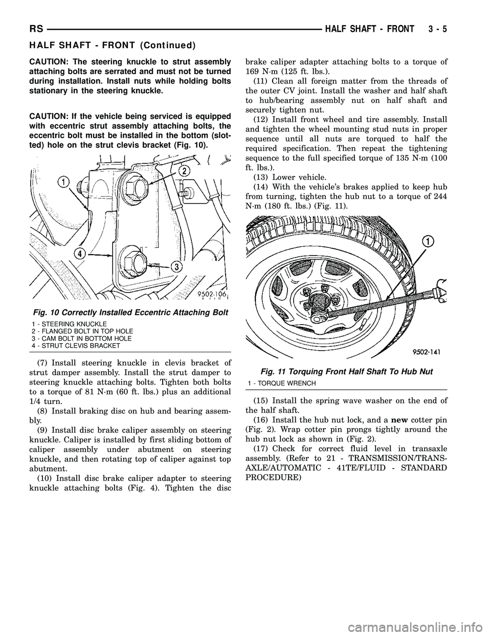
CAUTION: The steering knuckle to strut assembly
attaching bolts are serrated and must not be turned
during installation. Install nuts while holding bolts
stationary in the steering knuckle.
CAUTION: If the vehicle being serviced is equipped
with eccentric strut assembly attaching bolts, the
eccentric bolt must be installed in the bottom (slot-
ted) hole on the strut clevis bracket (Fig. 10).
(7) Install steering knuckle in clevis bracket of
strut damper assembly. Install the strut damper to
steering knuckle attaching bolts. Tighten both bolts
to a torque of 81 N´m (60 ft. lbs.) plus an additional
1/4 turn.
(8) Install braking disc on hub and bearing assem-
bly.
(9) Install disc brake caliper assembly on steering
knuckle. Caliper is installed by first sliding bottom of
caliper assembly under abutment on steering
knuckle, and then rotating top of caliper against top
abutment.
(10) Install disc brake caliper adapter to steering
knuckle attaching bolts (Fig. 4). Tighten the discbrake caliper adapter attaching bolts to a torque of
169 N´m (125 ft. lbs.).
(11) Clean all foreign matter from the threads of
the outer CV joint. Install the washer and half shaft
to hub/bearing assembly nut on half shaft and
securely tighten nut.
(12) Install front wheel and tire assembly. Install
and tighten the wheel mounting stud nuts in proper
sequence until all nuts are torqued to half the
required specification. Then repeat the tightening
sequence to the full specified torque of 135 N´m (100
ft. lbs.).
(13) Lower vehicle.
(14) With the vehicle's brakes applied to keep hub
from turning, tighten the hub nut to a torque of 244
N´m (180 ft. lbs.) (Fig. 11).
(15) Install the spring wave washer on the end of
the half shaft.
(16) Install the hub nut lock, and anewcotter pin
(Fig. 2). Wrap cotter pin prongs tightly around the
hub nut lock as shown in (Fig. 2).
(17) Check for correct fluid level in transaxle
assembly. (Refer to 21 - TRANSMISSION/TRANS-
AXLE/AUTOMATIC - 41TE/FLUID - STANDARD
PROCEDURE)
Fig. 10 Correctly Installed Eccentric Attaching Bolt
1 - STEERING KNUCKLE
2 - FLANGED BOLT IN TOP HOLE
3 - CAM BOLT IN BOTTOM HOLE
4 - STRUT CLEVIS BRACKET
Fig. 11 Torquing Front Half Shaft To Hub Nut
1 - TORQUE WRENCH
RSHALF SHAFT - FRONT3-5
HALF SHAFT - FRONT (Continued)
Page 122 of 2585

REAR DRIVELINE MODULE
TABLE OF CONTENTS
page page
REAR DRIVELINE MODULE
DESCRIPTION.........................23
OPERATION...........................23
DIAGNOSIS AND TESTING
DIAGNOSIS AND TESTING - REAR
DRIVELINE MODULE NOISE.............24
DIAGNOSIS AND TESTING - REAR
DRIVELINE MODULE OPERATION........26
REMOVAL.............................26
DISASSEMBLY.........................27
ASSEMBLY............................29
INSTALLATION.........................33
SPECIFICATIONS - REAR DRIVELINE
MODULE............................34
SPECIAL TOOLS.......................34
BI-DIRECTIONAL OVERRUNNING CLUTCH
DESCRIPTION.........................34
OPERATION...........................36
DIFFERENTIAL ASSEMBLY
DESCRIPTION.........................39OPERATION...........................39
FLUID - DIFFERENTIAL ASSEMBLY
STANDARD PROCEDURE - DIFFERENTIAL
ASSEMBLY FLUID CHANGE.............40
FLUID - OVERRUNNING CLUTCH HOUSING
STANDARD PROCEDURE - OVERRUNNING
CLUTCH HOUSING FLUID CHANGE.......41
VISCOUS COUPLER
DESCRIPTION.........................41
OPERATION...........................42
TORQUE ARM
REMOVAL.............................44
INSTALLATION.........................44
INPUT FLANGE SEAL
REMOVAL.............................44
INSTALLATION.........................45
OUTPUT FLANGE SEAL
REMOVAL.............................45
INSTALLATION.........................46
REAR DRIVELINE MODULE
DESCRIPTION
The rear driveline module assembly (Fig. 1) con-
sists of four main components:
²Bi-Directional Overrunning Clutch (BOC)
²Viscous Coupling
²Differential Assembly
²Torque Arm
The viscous coupling and bi-directional overrun-
ning clutch are contained within an overrunning
clutch housing, which fastens to the differential
assembly. The overrunning clutch housing and differ-
ential assembly have unique fluid sumps, each
requiring their own type and capacity of fluid. The
overrunning clutch housing requires MopartATF+4
(Automatic Transmission FluidÐType 9602) or equiv-
alent. The differential assembly requires Mopart
80W-90 Gear and Axle Lubricant.
Driveline module service is limited to the following
components:
²Differential Assembly (serviced only as assem-
bly)
²Viscous Coupling
²Bi-Directional Overrunning Clutch (BOC)
²Overrunning Clutch Housing²Seals (Input Flange, Output Flange, Overrun-
ning Clutch Housing O-rings)
²Input Flange/Shield
²Torque Arm
²Vents
²Fasteners
OPERATION
The primary benefits of All Wheel Drive are:
²Superior straight line acceleration, and corner-
ing on all surfaces
²Better traction and handling under adverse con-
ditions, resulting in improved hill climbing ability
and safer driving.
The heart of the system is an inter-axle viscous
coupling. The vehicle retains predominantly front-
wheel drive characteristics, but the All Wheel Drive
capability takes effect when the front wheels start to
slip. Under normal level road, straight line driving,
100% of the torque is allocated to the front wheels.
The viscous coupling controls and distributes torque/
power to the rear wheels. The viscous coupling trans-
mits torque to the rear wheels in proportion of the
amount of the slippage at the front wheels. Thais
variable torque distribution is automatic with no
driver inputs required. The coupling is similar to a
multi-plate clutch. It consists of a series of closely
spaced discs, which are alternately connected to the
RSREAR DRIVELINE MODULE3-23
Page 123 of 2585

front and rear drive units. The unit is totally sealed
and partially filled with silicone fluid. There is no
adjustment, maintenance or fluid checks required
during the life of the unit.
The overrunning clutch allows the rear wheels to
overrun the front wheels during a rapid front wheel
lock braking maneuver. The overrunning action pre-
vents any feed-back of front wheel braking torque to
the rear wheels. It also allows the braking system to
control the braking behavior as a two wheel drive
(2WD) vehicle.
The overrunning clutch housing has a separate oil
sump and is filled independently from the differen-
tial. The fill plug is located on the side of the over-
running clutch case. When filling the overrunning
clutch with lubricant use MopartATF+4 (Automatic
Transmission FluidÐType 9602) or equivalent.
The differential assembly contains a conventional
open differential with hypoid ring gear and pinion
gear set. The hypoid gears are lubricated by SAE
80W-90 gear lubricant.DIAGNOSIS AND TESTING
DIAGNOSIS AND TESTING - REAR DRIVELINE
MODULE NOISE
Different sources can be the cause of noise that the
rear driveline module assembly is suspected of mak-
ing. Refer to the following causes for noise diagnosis.
DRIVELINE MODULE ASSEMBLY NOISE
The most important part of driveline module ser-
vice is properly identifying the cause of failures and
noise complaints. The cause of most driveline module
failures is relatively easy to identify. The cause of
driveline module noise is more difficult to identify.
If vehicle noise becomes intolerable, an effort
should be made to isolate the noise. Many noises that
are reported as coming from the driveline module
may actually originate at other sources. For example:
²Tires
²Road surfaces
²Wheel bearings
Fig. 1 AWD Driveline Module Assembly
1 - TORQUE ARM 8 - WASHER 15 - PLUG-OVERRUNNING CLUTCH
HOUSING DRAIN
2 - INPUT FLANGE 9 - BI-DIRECTIONAL OVERRUNNING
CLUTCH (BOC)16 - SNAP RING
3 - FLANGE NUT 10 - VISCOUS COUPLER 17 - BEARING
4 - WASHER 11 - SHIM (SELECT) 18 - OVERRUNING CLUTCH HOUSING
5 - SHIELD 12 - O-RING 19 - SEAL-INPUT FLANGE
6 - VENT 13 - DIFFERENTIAL ASSEMBLY
7 - O-RING 14 - PLUG-DIFFERENTIAL FILL
3 - 24 REAR DRIVELINE MODULERS
REAR DRIVELINE MODULE (Continued)