2004 CHRYSLER VOYAGER Power steering
[x] Cancel search: Power steeringPage 2416 of 2585

heater control has detected a failure and a Diagnostic
Trouble Code (DTC) has been set. Refer to Body
Diagnostic Procedures to perform further diagnosis.
The LEDs or graphics will continue to flash even
after the ignition switch is cycled Off and On, until a
successful calibration is completed or until the vehi-
cle has been driven about 13 kilometers (8 miles).
REMOVAL
WARNING: ON VEHICLES EQUIPPED WITH AIR-
BAGS, DISABLE THE AIRBAG SYSTEM BEFORE
ATTEMPTING ANY STEERING WHEEL, STEERING
COLUMN, OR INSTRUMENT PANEL COMPONENT
DIAGNOSIS OR SERVICE. DISCONNECT AND ISO-
LATE THE BATTERY NEGATIVE (GROUND) CABLE,
THEN WAIT TWO MINUTES FOR THE AIRBAG SYS-
TEM CAPACITOR TO DISCHARGE BEFORE PER-
FORMING FURTHER DIAGNOSIS OR SERVICE. THIS
IS THE ONLY SURE WAY TO DISABLE THE AIRBAG
SYSTEM. FAILURE TO TAKE THE PROPER PRE-
CAUTIONS COULD RESULT IN ACCIDENTAL AIR-
BAG DEPLOYMENT AND POSSIBLE PERSONAL
INJURY.
(1) Disconnect and isolate the battery negative
cable.
(2) Remove the center bezel from the instrument
panel (Refer to 23 - BODY/INSTRUMENT PANEL/
INSTRUMENT PANEL CENTER BEZEL -
REMOVAL).
(3) Place the instrument panel center bezel unit
face down on a suitable work surface. Take the
proper precautions to protect the center bezel from
cosmetic damage.
(4) If the vehicle is equipped with the optional
Automatic Temperature Control (ATC) system, dis-
connect the infrared sensor jumper harness connector
from the receptacle on the back of the A/C-heater
control (Fig. 9).
(5) Remove the six screws that secure the A/C-
heater control to the back of the instrument panel
center bezel.
(6) Remove the A/C-heater control from the instru-
ment panel center bezel.
INSTALLATION
(1) Position the A/C-heater control onto the back of
instrument panel center bezel.
(2) Install the six screws that secure the A/C-
heater control to the back of the instrument panel
center bezel. Tighten the screws to 2 N´m (17 in.
lbs.).
(3) If the vehicle is equipped with the optional
ATC system, reconnect the infrared sensor jumper
harness connector to A/C-heater control.(4) Install the center bezel onto the instrument
panel (Refer to 23 - BODY/INSTRUMENT PANEL/
INSTRUMENT PANEL CENTER BEZEL - INSTAL-
LATION).
(5) Reconnect the battery negative cable.
A/C PRESSURE TRANSDUCER
DESCRIPTION
The A/C pressure transducer is a switch that is
installed on a fitting located on the refrigerant liquid
line between the receiver/drier and the expansion
valve in the right rear corner of the engine compart-
ment. An internally threaded hex fitting on the
transducer connects it to the externally threaded
Schrader-type fitting on the liquid line. A rubber
O-ring seals the connection between the transducer
and the liquid line fitting. Three terminals within a
molded plastic connector receptacle on the top of the
transducer connect it to the vehicle electrical system
through a wire lead and connector of the headlamp
and dash wire harness.
The A/C pressure transducer cannot be adjusted or
repaired and, if faulty or damaged, it must be
replaced.
OPERATION
The A/C pressure transducer monitors the pres-
sures in the high side of the refrigerant system
through its connection to a fitting on the liquid line.
The transducer will change its internal resistance in
response to the pressures it monitors. The power-
train control module (PCM) provides a five volt ref-
Fig. 9 A/C-Heater Control
1 - INFRARED SENSOR CONNECTOR (ATC ONLY)
2 - INFRARED SENSOR HARNESS (ATC ONLY)
3 - A/C-HEATER CONTROL AREA
4 - SCREW (6)
5- INSTRUMENT PANEL CENTER BEZEL
RSCONTROLS - FRONT24-21
A/C HEATER CONTROL (Continued)
Page 2421 of 2585
BLOWER MOTOR RESISTOR
BLOCK
DESCRIPTION
A blower motor resistor is used on this model when
it is equipped with the manual heater-A/C system.
Models equipped with the optional Automatic Tem-
perature Control (ATC) system use a blower power
module, instead of the blower motor resistor block
(Refer to 24 - HEATING & AIR CONDITIONING/
CONTROLS/POWER MODULE - DESCRIPTION).
The blower motor resistor block is mounted to the
rear of the HVAC housing, directly behind the glove
box opening in the instrument panel. The resistor
block consists of a molded plastic mounting plate
with two integral connector receptacles. Concealed
behind the mounting plate are four coiled resistor
wires contained within a protective stamped steel
cage. The blower motor resistor block is accessed for
service by removing the glove box from the instru-
ment panel.
OPERATION
The blower motor resistor block is connected to the
vehicle electrical system through a dedicated take
out and connector of the instrument panel wire har-
ness. A second connector receptacle receives the pig-
tail wire connector from the blower motor. The
blower motor resistor has multiple resistor wires,
each of which will reduce the current flow through
the blower motor to change the blower motor speed.
The blower motor switch in the manual heater-A/C
system directs the ground path for the blower motor
through the correct resistor wire to obtain the
selected speed.
With the blower motor switch in the lowest speed
position, the ground path for the motor is applied
through all of the resistor wires. Each higher speed
selected with the blower motor switch applies the
blower motor ground path through fewer of the resis-
tor wires, increasing the blower motor speed.
The blower motor resistor cannot be adjusted or
repaired and, if faulty or damaged, it must be
replaced.
DIAGNOSIS AND TESTING - BLOWER MOTOR
RESISTOR BLOCK
WARNING: ON VEHICLES EQUIPPED WITH AIR-
BAGS, DISABLE THE AIRBAG SYSTEM BEFORE
ATTEMPTING ANY STEERING WHEEL, STEERING
COLUMN, OR INSTRUMENT PANEL COMPONENT
DIAGNOSIS OR SERVICE. DISCONNECT AND ISO-
LATE THE BATTERY NEGATIVE (GROUND) CABLE,
THEN WAIT TWO MINUTES FOR THE AIRBAG SYS-TEM CAPACITOR TO DISCHARGE BEFORE PER-
FORMING FURTHER DIAGNOSIS OR SERVICE. THIS
IS THE ONLY SURE WAY TO DISABLE THE AIRBAG
SYSTEM. FAILURE TO TAKE THE PROPER PRE-
CAUTIONS COULD RESULT IN ACCIDENTAL AIR-
BAG DEPLOYMENT AND POSSIBLE PERSONAL
INJURY.
For circuit descriptions and diagrams, refer to the
appropriate wiring information. The wiring informa-
tion includes wiring diagrams, proper wire and con-
nector repair procedures, further details on wire
harness routing and retention, as well as pin-out and
location views for the various wire harness connec-
tors, splices and grounds.
(1) Disconnect and isolate the battery negative
cable.
(2) Remove the glove box from the instrument
panel (Refer to 23 - BODY/INSTRUMENT PANEL/
GLOVE BOX - REMOVAL).
(3) Disconnect the two wire harness connectors
from the blower motor resistor block.
(4) Check for continuity between each of the
blower motor switch input terminals of the resistor
and the resistor output terminal. In each case there
should be continuity. If OK, repair the wire harness
circuits between the blower motor switch and the
blower motor resistor, blower motor or blower motor
relay as required. If not OK, replace the faulty
blower motor resistor block.
REMOVAL
WARNING: ON VEHICLES EQUIPPED WITH AIR-
BAGS, DISABLE THE AIRBAG SYSTEM BEFORE
ATTEMPTING ANY STEERING WHEEL, STEERING
COLUMN, OR INSTRUMENT PANEL COMPONENT
DIAGNOSIS OR SERVICE. DISCONNECT AND ISO-
LATE THE BATTERY NEGATIVE (GROUND) CABLE,
THEN WAIT TWO MINUTES FOR THE AIRBAG SYS-
TEM CAPACITOR TO DISCHARGE BEFORE PER-
FORMING FURTHER DIAGNOSIS OR SERVICE. THIS
IS THE ONLY SURE WAY TO DISABLE THE AIRBAG
SYSTEM. FAILURE TO TAKE THE PROPER PRE-
CAUTIONS COULD RESULT IN ACCIDENTAL AIR-
BAG DEPLOYMENT AND POSSIBLE PERSONAL
INJURY.
WARNING: THE BLOWER MOTOR RESISTOR
BLOCK MAY GET VERY HOT DURING NORMAL
OPERATION. IF THE BLOWER MOTOR WAS
TURNED ON PRIOR TO SERVICING THE BLOWER
MOTOR RESISTOR BLOCK, WAIT FIVE MINUTES
TO ALLOW THE BLOWER MOTOR RESISTORS TO
COOL BEFORE PERFORMING DIAGNOSIS OR SER-
VICE. FAILURE TO TAKE THIS PRECAUTION CAN
RESULT IN PERSONAL INJURY.
24 - 26 CONTROLS - FRONTRS
Page 2426 of 2585
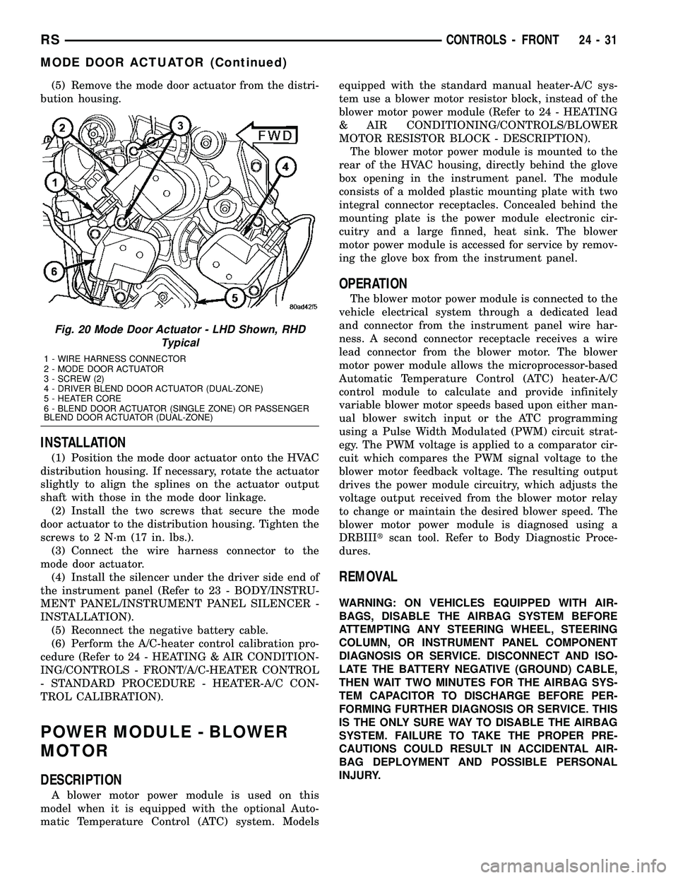
(5) Remove the mode door actuator from the distri-
bution housing.
INSTALLATION
(1) Position the mode door actuator onto the HVAC
distribution housing. If necessary, rotate the actuator
slightly to align the splines on the actuator output
shaft with those in the mode door linkage.
(2) Install the two screws that secure the mode
door actuator to the distribution housing. Tighten the
screws to 2 N´m (17 in. lbs.).
(3) Connect the wire harness connector to the
mode door actuator.
(4) Install the silencer under the driver side end of
the instrument panel (Refer to 23 - BODY/INSTRU-
MENT PANEL/INSTRUMENT PANEL SILENCER -
INSTALLATION).
(5) Reconnect the negative battery cable.
(6) Perform the A/C-heater control calibration pro-
cedure (Refer to 24 - HEATING & AIR CONDITION-
ING/CONTROLS - FRONT/A/C-HEATER CONTROL
- STANDARD PROCEDURE - HEATER-A/C CON-
TROL CALIBRATION).
POWER MODULE - BLOWER
MOTOR
DESCRIPTION
A blower motor power module is used on this
model when it is equipped with the optional Auto-
matic Temperature Control (ATC) system. Modelsequipped with the standard manual heater-A/C sys-
tem use a blower motor resistor block, instead of the
blower motor power module (Refer to 24 - HEATING
& AIR CONDITIONING/CONTROLS/BLOWER
MOTOR RESISTOR BLOCK - DESCRIPTION).
The blower motor power module is mounted to the
rear of the HVAC housing, directly behind the glove
box opening in the instrument panel. The module
consists of a molded plastic mounting plate with two
integral connector receptacles. Concealed behind the
mounting plate is the power module electronic cir-
cuitry and a large finned, heat sink. The blower
motor power module is accessed for service by remov-
ing the glove box from the instrument panel.
OPERATION
The blower motor power module is connected to the
vehicle electrical system through a dedicated lead
and connector from the instrument panel wire har-
ness. A second connector receptacle receives a wire
lead connector from the blower motor. The blower
motor power module allows the microprocessor-based
Automatic Temperature Control (ATC) heater-A/C
control module to calculate and provide infinitely
variable blower motor speeds based upon either man-
ual blower switch input or the ATC programming
using a Pulse Width Modulated (PWM) circuit strat-
egy. The PWM voltage is applied to a comparator cir-
cuit which compares the PWM signal voltage to the
blower motor feedback voltage. The resulting output
drives the power module circuitry, which adjusts the
voltage output received from the blower motor relay
to change or maintain the desired blower speed. The
blower motor power module is diagnosed using a
DRBIIItscan tool. Refer to Body Diagnostic Proce-
dures.
REMOVAL
WARNING: ON VEHICLES EQUIPPED WITH AIR-
BAGS, DISABLE THE AIRBAG SYSTEM BEFORE
ATTEMPTING ANY STEERING WHEEL, STEERING
COLUMN, OR INSTRUMENT PANEL COMPONENT
DIAGNOSIS OR SERVICE. DISCONNECT AND ISO-
LATE THE BATTERY NEGATIVE (GROUND) CABLE,
THEN WAIT TWO MINUTES FOR THE AIRBAG SYS-
TEM CAPACITOR TO DISCHARGE BEFORE PER-
FORMING FURTHER DIAGNOSIS OR SERVICE. THIS
IS THE ONLY SURE WAY TO DISABLE THE AIRBAG
SYSTEM. FAILURE TO TAKE THE PROPER PRE-
CAUTIONS COULD RESULT IN ACCIDENTAL AIR-
BAG DEPLOYMENT AND POSSIBLE PERSONAL
INJURY.
Fig. 20 Mode Door Actuator - LHD Shown, RHD
Typical
1 - WIRE HARNESS CONNECTOR
2 - MODE DOOR ACTUATOR
3 - SCREW (2)
4 - DRIVER BLEND DOOR ACTUATOR (DUAL-ZONE)
5 - HEATER CORE
6 - BLEND DOOR ACTUATOR (SINGLE ZONE) OR PASSENGER
BLEND DOOR ACTUATOR (DUAL-ZONE)
RSCONTROLS - FRONT24-31
MODE DOOR ACTUATOR (Continued)
Page 2442 of 2585
blower motor to regulate the blower motor ground
path it provides. The blower motor and wheel are
used to control the velocity of air moving through the
HVAC housing by spinning the blower wheel within
the housing at the selected speed or, in the ATC sys-
tem, at the selected or programmed speed.
DIAGNOSIS AND TESTING - BLOWER MOTOR
BLOWER MOTOR INOPERATIVE
WARNING: ON VEHICLES EQUIPPED WITH AIR-
BAGS, DISABLE THE AIRBAG SYSTEM BEFORE
ATTEMPTING ANY STEERING WHEEL, STEERING
COLUMN, OR INSTRUMENT PANEL COMPONENT
DIAGNOSIS OR SERVICE. DISCONNECT AND ISO-
LATE THE BATTERY NEGATIVE (GROUND) CABLE,
THEN WAIT TWO MINUTES FOR THE AIRBAG SYS-
TEM CAPACITOR TO DISCHARGE BEFORE PER-
FORMING FURTHER DIAGNOSIS OR SERVICE. THIS
IS THE ONLY SURE WAY TO DISABLE THE AIRBAG
SYSTEM. FAILURE TO TAKE THE PROPER PRE-
CAUTIONS COULD RESULT IN ACCIDENTAL AIR-
BAG DEPLOYMENT AND POSSIBLE PERSONAL
INJURY.
For circuit descriptions and diagrams, refer to the
appropriate wiring information. The wiring informa-
tion includes wiring, diagrams, proper wire and con-
nector repair procedures, further details on wire
harness routing and retention, as well as pin-out and
location views for the various wire harness connec-
tors, splices and grounds.
BLOWER MOTOR ELECTRICAL DIAGNOSIS
(1) Check the fuse (Fuse 10 - 40 ampere) in the
Integrated Power Module (IPM). If OK, go to Step 2.
If not OK, repair the shorted circuit or component as
required and replace the faulty fuse.
(2) Turn the ignition switch to the On position. Be
certain that the A/C-heater control power is turned
on. Check for battery voltage at the fuse (Fuse 10 -
40 ampere) in the IPM. If OK, go to Step 3. If not
OK, check the front blower motor relay.
(3) Turn the ignition switch to the Off position.
Disconnect and isolate the battery negative cable.
Disconnect the front HVAC wire harness connector
for the front blower motor resistor block (Manual
Temperature Control) or the front blower motor
power module (Automatic Temperature Control) from
the resistor or module connector receptacle. Recon-
nect the battery negative cable. Turn the ignition
switch to the On position. Be certain that the A/C-
heater control power is turned on. Check for battery
voltage at the fused front blower motor relay output
circuit cavity of the front HVAC wire harness connec-
tor for the front blower motor resistor block (MTC) orthe front blower motor power module (ATC). If OK,
go to Step 4. If not OK, repair the open fused front
blower motor relay output circuit to the IPM as
required.
(4) Turn the ignition switch to the Off position.
Disconnect and isolate the battery negative cable.
Disconnect the front blower motor pigtail wire con-
nector from the connector receptacle of the front
blower motor resistor block (MTC) or the front
blower motor power module (ATC). Use jumper wires
to connect a battery and ground feeds to the blower
motor pigtail wire connector. The blower motor
should operate. If OK with MTC, proceed to diagno-
sis of the front blower motor resistor block (Refer to
24 - HEATING & AIR CONDITIONING/CONTROLS
- FRONT/BLOWER MOTOR RESISTOR - DIAGNO-
SIS AND TESTING). If OK with ATC, use a DRBIII
scan tool to diagnose the front blower motor power
module. Refer to Body Diagnostic information. If not
OK with MTC or ATC, replace the faulty front blower
motor.
BLOWER MOTOR NOISE OR VIBRATION
Refer to the Blower Motor Noise/Vibration Diagno-
sis chart for basic checks of the blower motor when a
vibration or noise is present (Fig. 7).
REMOVAL
WARNING: ON VEHICLES EQUIPPED WITH AIR-
BAGS, DISABLE THE AIRBAG SYSTEM BEFORE
ATTEMPTING ANY STEERING WHEEL, STEERING
COLUMN, OR INSTRUMENT PANEL COMPONENT
DIAGNOSIS OR SERVICE. DISCONNECT AND ISO-
LATE THE BATTERY NEGATIVE (GROUND) CABLE,
THEN WAIT TWO MINUTES FOR THE AIRBAG SYS-
TEM CAPACITOR TO DISCHARGE BEFORE PER-
FORMING FURTHER DIAGNOSIS OR SERVICE. THIS
IS THE ONLY SURE WAY TO DISABLE THE AIRBAG
SYSTEM. FAILURE TO TAKE THE PROPER PRE-
CAUTIONS COULD RESULT IN AN ACCIDENTAL
AIRBAG DEPLOYMENT AND POSSIBLE PERSONAL
INJURY.
NOTE: The blower motor is located on the passen-
ger side of the vehicle under the instrument panel.
The blower motor can be removed from the vehicle
without having to remove the HVAC housing.
(1) Disconnect and isolate the battery negative
cable.
(2) Remove the passenger side door sill plate and
cowl panel.
(3) Pull back the carpet to access the front lower
air intake screw.
RSDISTRIBUTION - FRONT24-47
BLOWER MOTOR (Continued)
Page 2445 of 2585
(6) Install the four screws (from the bottom) that
secure the lower air inlet housing to the lower HVAC
housing. Tighten the screws to 2 N´m (17 in. lbs.).
(7) Install the one screw (from the top) that
secures the lower air inlet housing to the upper air
intake housing. Tighten the screws to 2 N´m (17 in.
lbs.).
(8) Connect the blower motor pigtail harness con-
nector to the blower motor resistor block or power
module, depending how vehicle is equipped.
(9) Install the recirculation door actuator (Refer to
24 - HEATING & AIR CONDITIONING/CONTROLS/
RECIRCULATION DOOR ACTUATOR - INSTALLA-
TION).
(10) Install the recirculation door actuator wire
harness lead into the routing clip on the lower air
inlet housing.
(11) Reinstall the carpet.
(12) Install the passenger side door sill plate and
cowl panel.
(13) Reconnect the battery negative cable.
(14) Perform the heater-A/C control calibration
procedure (Refer to 24 - HEATING & AIR CONDI-
TIONING/CONTROLS - FRONT/A/C-HEATER CON-
TROL - STANDARD PROCEDURE - HEATER-A/C
CONTROL CALIBRATION).
DEFROSTER DUCT
REMOVAL
WARNING: ON VEHICLES EQUIPPED WITH AIR-
BAGS, DISABLE THE AIRBAG SYSTEM BEFORE
ATTEMPTING ANY STEERING WHEEL, STEERING
COLUMN, OR INSTRUMENT PANEL COMPONENT
DIAGNOSIS OR SERVICE. DISCONNECT AND ISO-
LATE THE BATTERY NEGATIVE (GROUND) CABLE,
THEN WAIT TWO MINUTES FOR THE AIRBAG SYS-
TEM CAPACITOR TO DISCHARGE BEFORE PER-
FORMING FURTHER DIAGNOSIS OR SERVICE. THIS
IS THE ONLY SURE WAY TO DISABLE THE AIRBAG
SYSTEM. FAILURE TO TAKE THE PROPER PRE-
CAUTIONS COULD RESULT IN ACCIDENTAL AIR-
BAG DEPLOYMENT AND POSSIBLE PERSONAL
INJURY.
(1) Disconnect and isolate the battery negative
cable.
(2) Remove the instrument panel from the vehicle.
(Refer to 23 - BODY/INSTRUMENT PANEL/IN-
STRUMENT PANEL ASSEMBLY - REMOVAL).
(3) Place the instrument panel face down on a
suitable work surface. Be certain to take the proper
precautions to protect the face of the instrument
panel from cosmetic damage.(4) Remove the fasteners that secure the defroster
duct to the instrument panel armature.
(5) Remove the defroster duct from the instrument
panel.
INSTALLATION
WARNING: ON VEHICLES EQUIPPED WITH AIR-
BAGS, DISABLE THE AIRBAG SYSTEM BEFORE
ATTEMPTING ANY STEERING WHEEL, STEERING
COLUMN, OR INSTRUMENT PANEL COMPONENT
DIAGNOSIS OR SERVICE. DISCONNECT AND ISO-
LATE THE BATTERY NEGATIVE (GROUND) CABLE,
THEN WAIT TWO MINUTES FOR THE AIRBAG SYS-
TEM CAPACITOR TO DISCHARGE BEFORE PER-
FORMING FURTHER DIAGNOSIS OR SERVICE. THIS
IS THE ONLY SURE WAY TO DISABLE THE AIRBAG
SYSTEM. FAILURE TO TAKE THE PROPER PRE-
CAUTIONS COULD RESULT IN ACCIDENTAL AIR-
BAG DEPLOYMENT AND POSSIBLE PERSONAL
INJURY.
(1) Position the defroster duct to the instrument
panel.
(2) Install the fasteners that secure the defroster
duct to the instrument panel armature.
(3) Reinstall the instrument panel in the vehicle.
(Refer to 23 - BODY/INSTRUMENT PANEL/IN-
STRUMENT PANEL ASSEMBLY - INSTALLA-
TION).
(4) Reconnect the battery negative cable.
FLOOR DISTRIBUTION DUCTS
REMOVAL
(1) Roll back the carpet on the front floor from
under the instrument panel toward the rear of the
vehicle (Refer to 23 - BODY/INTERIOR/CARPETS
AND FLOOR MATS - REMOVAL).
(2) Lift the center floor distribution duct upward
far enough to disengage its locator hole from the
weld stud on the front floor panel (Fig. 11).
(3) Pull the center floor distribution duct rearward
far enough to disengage it from the floor outlet of the
HVAC housing.
(4) Disassemble the right and/or left floor distribu-
tion ducts from the center floor distribution duct as
required.
INSTALLATION
(1) Assemble the right and/or left floor distribution
ducts onto the center floor distribution duct as
required.
(2) Slide the center floor distribution duct under
the instrument panel center stack far enough to
engage it to the floor outlet of the HVAC housing.
24 - 50 DISTRIBUTION - FRONTRS
BLOWER MOTOR (Continued)
Page 2479 of 2585
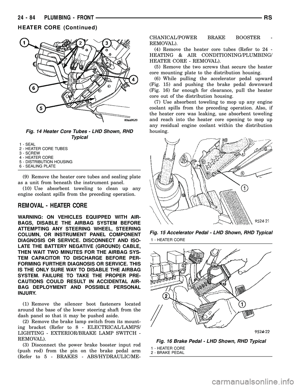
(9) Remove the heater core tubes and sealing plate
as a unit from beneath the instrument panel.
(10) Use absorbent toweling to clean up any
engine coolant spills from the preceding operation.
REMOVAL - HEATER CORE
WARNING: ON VEHICLES EQUIPPED WITH AIR-
BAGS, DISABLE THE AIRBAG SYSTEM BEFORE
ATTEMPTING ANY STEERING WHEEL, STEERING
COLUMN, OR INSTRUMENT PANEL COMPONENT
DIAGNOSIS OR SERVICE. DISCONNECT AND ISO-
LATE THE BATTERY NEGATIVE (GROUND) CABLE,
THEN WAIT TWO MINUTES FOR THE AIRBAG SYS-
TEM CAPACITOR TO DISCHARGE BEFORE PER-
FORMING FURTHER DIAGNOSIS OR SERVICE. THIS
IS THE ONLY SURE WAY TO DISABLE THE AIRBAG
SYSTEM. FAILURE TO TAKE THE PROPER PRE-
CAUTIONS COULD RESULT IN ACCIDENTAL AIR-
BAG DEPLOYMENT AND POSSIBLE PERSONAL
INJURY.
(1) Remove the silencer boot fasteners located
around the base of the lower steering shaft from the
dash panel so that it may be pushed aside.
(2) Remove the brake lamp switch from its mount-
ing bracket (Refer to 8 - ELECTRICAL/LAMPS/
LIGHTING - EXTERIOR/BRAKE LAMP SWITCH -
REMOVAL).
(3) Disconnect the power brake booster input rod
(push rod) from the pin on the brake pedal arm
(Refer to 5 - BRAKES - ABS/HYDRAULIC/ME-CHANICAL/POWER BRAKE BOOSTER -
REMOVAL).
(4) Remove the heater core tubes (Refer to 24 -
HEATING & AIR CONDITIONING/PLUMBING/
HEATER CORE - REMOVAL).
(5) Remove the two screws that secure the heater
core mounting plate to the distribution housing.
(6) While pulling the accelerator pedal upward
(Fig. 15) and pushing the brake pedal downward
(Fig. 16) far enough for clearance, pull the heater
core out of the distribution housing.
(7) Use absorbent toweling to mop up any engine
coolant spills from the preceding operation. Also, if
the heater core was leaking, use absorbent toweling
and reach into the heater core opening to mop up
any residual engine coolant within the distribution
housing.
Fig. 14 Heater Core Tubes - LHD Shown, RHD
Typical
1 - SEAL
2 - HEATER CORE TUBES
3 - SCREW
4 - HEATER CORE
5 - DISTRIBUTION HOUSING
6 - SEALING PLATE
Fig. 15 Accelerator Pedal - LHD Shown, RHD Typical
1 - HEATER CORE
Fig. 16 Brake Pedal - LHD Shown, RHD Typical
1 - HEATER CORE
2 - BRAKE PEDAL
24 - 84 PLUMBING - FRONTRS
HEATER CORE (Continued)
Page 2480 of 2585
INSTALLATION
INSTALLATION - HEATER CORE TUBES
(1) Remove the plugs or tape from both heater core
tube fittings and both heater core ports.
(2) Position the heater core tubes and sealing plate
as a unit beneath the instrument panel.
(3) Align the engine compartment ends of both
heater core tubes with the openings in the dash
panel seal and push them simultaneously forward
through the seal far enough to engage the heater
core ends of the tubes with the heater core supply
and return ports.
(4) Position both heater core tubes and the sealing
plate simultaneously to the heater core supply and
return ports.
NOTE: The heater core tubes each have a slot that
must be indexed to a location tab within each of the
heater core ports. Adjust the position of the tubes
as required so that the sealing plate fits flush
against the heater core supply and return ports,
which indicates that the tubes are properly indexed.
(5) Index both heater core tubes to the heater core
ports.
(6) Install the screw that secures the heater core
tube sealing plate to the heater core supply and
return ports. Tighten the screw to 3 N´m (27 in. lbs.).
(7) Install the silencer under the driver side end of
the instrument panel.
(8) Connect the heater hoses to the heater hose
tubes (Refer to 24 - HEATING & AIR CONDITION-
ING/PLUMBING/HEATER INLET HOSE - INSTAL-
LATION) and(Refer to 24 - HEATING & AIR
CONDITIONING/PLUMBING/HEATER RETURN
HOSE - INSTALLATION).
(9) Reconnect the battery negative cable.
(10) Refill the engine cooling system (Refer to 7 -
COOLING - STANDARD PROCEDURE - COOLING
SYSTEM REFILL).
INSTALLATION - HEATER CORE
(1) While pushing the brake pedal downward and
pulling the accelerator pedal upward far enough for
clearance, slide the heater core into the distribution
housing.
(2) Install the two screws that secure the heater
core mounting plate to the distribution housing.
Tighten the screws to 2 N´m (17 in. lbs.).
(3) Install the heater core tubes (Refer to 24 -
HEATING & AIR CONDITIONING/PLUMBING/
HEATER CORE - INSTALLATION).
(4) Reconnect the power brake booster input rod
(push rod) to the pin on the brake pedal arm (Referto 5 - BRAKES/HYDRAULIC/MECHANICAL/
POWER BRAKE BOOSTER - INSTALLATION).
(5) Reinstall the brake lamp switch into its mount-
ing bracket (Refer to 8 - ELECTRICAL/LAMPS/
LIGHTING - EXTERIOR/BRAKE LAMP SWITCH -
INSTALLATION).
(6) Reinstall the silencer boot around the base of
the lower steering shaft on the dash panel.
(7) Reconnect the battery negative cable.
(8) Refill the engine cooling system (Refer to 7 -
COOLING - STANDARD PROCEDURE - COOLING
SYSTEM REFILL).
(9) Operate system for two thermostat cycles to
assure the elimination of any air that may be
trapped within the cooling system.
HEATER INLET HOSE
REMOVAL
WARNING: REFER TO THE APPLICABLE WARN-
INGS AND CAUTIONS FOR THIS SYSTEM BEFORE
PERFORMING THE FOLLOWING OPERATION (Refer
to 24 - HEATING & AIR CONDITIONING/PLUMBING -
WARNING).
NOTE: The heater inlet hose is constructed from
formed steel tubing and rubber hoses. Depending
on application, the ends are secured to the heater
core, engine oil cooler or the engine by spring ten-
sion clamps.
(1) Drain the engine cooling system (Refer to 7 -
COOLING - STANDARD PROCEDURE - COOLING
SYSTEM DRAIN).
(2) Using spring tension clamp pliers, compress
and slide the clamps off of each end of the hose being
removed (Fig. 17), (Fig. 18) or (Fig. 19).
CAUTION:
DO NOT apply excessive pressure on heater tubes
or connections when removing heater hoses.
Excessive pressure may damage or deform the
tubes/heater core, causing an engine coolant leak.
(3) Disconnect each hose end by carefully twisting
the hose back and forth on the tube or nipple, while
gently pulling it away from the end of the tube or
nipple.
NOTE:
Replacement of the heater inlet hoses will be
required if the hose ends are cut for removal.
(4) If necessary, carefully cut the hose end and
peel the hose off of the tube or nipple.
RSPLUMBING - FRONT24-85
HEATER CORE (Continued)
Page 2517 of 2585
The following is a list of the monitored compo-
nents:
²Comprehensive Components
²Oxygen Sensor Monitor
²Oxygen Sensor Heater Monitor
²Catalyst Monitor
COMPREHENSIVE COMPONENTS
Along with the major monitors, OBD II requires
that the diagnostic system monitor any component
that could affect emissions levels. In many cases,
these components were being tested under OBD I.
The OBD I requirements focused mainly on testing
emissions-related components for electrical opens and
shorts.
However, OBD II also requires that inputs from
powertrain components to the PCM be tested for
rationality, and that outputs to powertrain compo-
nents from the PCM be tested forfunctionality.
Methods for monitoring the various Comprehensive
Component monitoring include:
(1) Circuit Continuity
²Open
²Shorted high
²Shorted to ground
(2) Rationality or Proper Functioning
²Inputs tested for rationality
²Outputs tested for functionality
NOTE: Comprehensive component monitors are
continuous. Therefore, enabling conditions do not
apply.
Input RationalityÐWhile input signals to the
PCM are constantly being monitored for electrical
opens and shorts, they are also tested for rationality.
This means that the input signal is compared against
other inputs and information to see if it makes sense
under the current conditions.
PCM sensor inputs that are checked for rationality
include:
²Manifold Absolute Pressure (MAP) Sensor
²Oxygen Sensor (O2S)
²Engine Coolant Temperature (ECT) Sensor
²Camshaft Position (CMP) Sensor
²Vehicle Speed Sensor
²Crankshaft Position (CKP) Sensor
²Intake/inlet Air Temperature (IAT) Sensor
²Throttle Position (TPS) Sensor
²Ambient Temperature Sensors
²Power Steering Switch
²Oxygen Sensor Heater
²Brake Switch
²Leak Detection Pump Switch or NVLD switch (if
equipped)
²P/N SwitchOutput FunctionalityÐPCM outputs are tested
for functionality in addition to testing for opens and
shorts. When the PCM provides a voltage to an out-
put component, it can verify that the command was
carried out by monitoring specific input signals for
expected changes. For example, when the PCM com-
mands the Idle Air Control (IAC) Motor to a specific
position under certain operating conditions, it expects
to see a specific (target) idle speed (RPM). If it does
not, it stores a DTC.
PCM outputs monitored for functionality include:
²Fuel Injectors
²Ignition Coils
²Idle Air Control
²Purge Solenoid
²EGR Solenoid (if equipped)
²LDP Solenoid or NVLD solenoid (if equipped)
²Radiator Fan Control
²Trans Controls
OXYGEN SENSOR (O2S) MONITOR
DESCRIPTIONÐEffective control of exhaust
emissions is achieved by an oxygen feedback system.
The most important element of the feedback system
is the O2S. The O2S is located in the exhaust path.
Once it reaches operating temperature 300É to 350ÉC
(572É to 662ÉF), the sensor generates a voltage that
is inversely proportional to the amount of oxygen in
the exhaust. When there is a large amount of oxygen
in the exhaust caused by a lean condition, the sensor
produces a low voltage, below 450 mV. When the oxy-
gen content is lower, caused by a rich condition, the
sensor produces a higher voltage, above 450mV (volt-
ages are offset by 2.5 volts on NGC vehicles).
The information obtained by the sensor is used to
calculate the fuel injector pulse width. The PCM is
programmed to maintain the optimum air/fuel ratio.
At this mixture ratio, the catalyst works best to
remove hydrocarbons (HC), carbon monoxide (CO)
and nitrous oxide (NOx) from the exhaust.
The O2S is also the main sensing element for the
EGR (if equipped), Catalyst and Fuel Monitors.
The O2S may fail in any or all of the following
manners:
²Slow response rate (Big Slope)
²Reduced output voltage (Half Cycle)
²Heater Performance
Slow Response Rate (Big Slope)ÐResponse rate
is the time required for the sensor to switch from
lean to rich signal output once it is exposed to a
richer than optimum A/F mixture or vice versa. As
the PCM adjusts the air/fuel ratio, the sensor must
be able to rapidly detect the change. As the sensor
ages, it could take longer to detect the changes in the
oxygen content of the exhaust gas. The rate of
change that an oxygen sensor experiences is called
25 - 2 EMISSIONS CONTROLRS
EMISSIONS CONTROL (Continued)