Page 1711 of 2585

SYNCHRONIZER
DESCRIPTION
The T850 transaxle uses two styles of synchronizer
assemblies; a conventional single-cone style is used
for the 5th/Reverse and 3rd/4th applications (Fig.
277), and a dual-cone style for the 1st/2nd gear appli-
cation (Fig. 278).
DISASSEMBLY
Place synchronizer in a clean shop towel and wrap.
Press on inner hub. Carefully open up shop towel
and remove springs, balls, keys, hub, and sleeve.
CLEANING
CLEAN
Do not attempt to clean the blocking rings in sol-
vent. The friction material will become contaminated.
Place synchronizer components in a suitable holder
and clean with solvent. Air dry.
INSPECTION
INSPECT
Proper inspection of components involve:
²
Teeth, for wear, scuffed, nicked, burred, or broken
teeth
²Keys, for wear or distortion
²Balls and springs, for distortion, cracks, or wear
If any of these conditions exist in these compo-
nents, replace as necessary.
ASSEMBLY
(1) Position synchronizer hub onto work bench.
Hub is non-directional.
(2) Install springs into hub slot.
(3) Insert key into hub and spring.
(4) Apply petroleum jelly to the hole in the key.
Insert balls into each key.
(5) Slide sleeve over the hub and depress balls as
you carefully slip the sleeve into position.
Fig. 276 Shift Fork/Shaft Components
1 - 5/R FORK
2 - SHAFT/LINK ASSEMBLY
3 - LINK
4 - 3/4 FORK
5 - 1/2 FORK
Fig. 277 3/4-5/R Synchronizer Assembly
1 - SLEEVE
2 - HUB
3 - BLOCKER RING (2)
4 - SPRING (3)
5 - KEY (3)
6 - BALL (3)
21 - 114 T850 MANUAL TRANSAXLERS
SHIFT FORK AND SHAFT (Continued)
Page 1759 of 2585

NO. 4 THRUST PLATE CHART
PART NUMBER THICKNESS
4431665AB 1.60mm (0.063 in.)
3836237AB 1.73mm (0.068 in.)
4431666AB 1.80mm (0.071 in.)
3836238AB 1.96mm (0.077 in.)
4431667AB 2.03mm (0.080 in.)
3836239AB 2.16mm (0.085 in.)
4431668AB 2.24mm (0.088 in.)
3836240AB 2.39mm (0.094 in.)
4431669AB 2.46mm (0.097 in.)
3836241AB 2.62mm (0.103 in.)
4446670AB 2.67mm (0.105 in.)
4446671AB 2.90mm (0.114 in.)
(53) Install input clutch assembly (Fig. 145).
(54) Install #1 caged needle bearing (Fig. 146).
CAUTION: The cooler bypass valve must be
replaced if transaxle failure has occurred. Do not
attempt to reuse or clean old valve.
(55) Install cooler bypass valve with o-ring end
towards rear of case (Fig. 147).
(56) Install oil pump gasket (Fig. 148).
Fig. 145 Install Input Clutch Assembly
1 - INPUT CLUTCH ASSEMBLY
2 - #4 THRUST WASHER
Fig. 146 Install Caged Needle Bearing
1 - #1 CAGED NEEDLE BEARING
2 - NOTE: TANGED SIDE OUT
Fig. 147 Install Cooler Bypass Valve
1 - COOLER BYPASS VALVE
Fig. 148 Install Oil Pump Gasket
1 - PUMP GASKET
21 - 162 41TE AUTOMATIC TRANSAXLERS
41TE AUTOMATIC TRANSAXLE (Continued)
Page 1821 of 2585
(21) Install the OD clutch pack (four frictions/three
steels) (Fig. 264).
(22) Install OD pressure plate waved snap ring
(Fig. 265).(23) Install the OD/Reverse pressure plate with
large step down (towards OD clutch pack) (Fig. 266).
(24) Install OD pressure plate flat snap ring (Fig.
267) (Fig. 268).
Fig. 264 Install OD Clutch Pack
1 - OVERDRIVE CLUTCH PACK
Fig. 265 Install Waved Snap Ring
1 - OVERDRIVE PRESSURE PLATE WAVED SNAP RING
2 - SCREWDRIVER
Fig. 266 OD/Reverse Pressure Plate
1 - OVERDRIVE/REVERSE PRESSURE PLATE
2 - (STEP SIDE DOWN)
Fig. 267 Install Flat Snap Ring
1 - ARBOR PRESS RAM
2 - TOOL 5059A
3 - FLAT SNAP RING
21 - 224 41TE AUTOMATIC TRANSAXLERS
INPUT CLUTCH ASSEMBLY (Continued)
Page 1823 of 2585

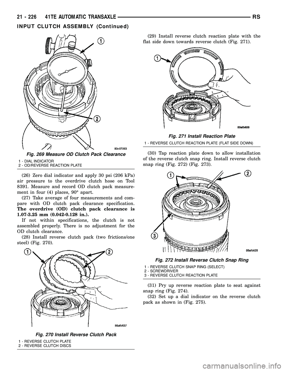
(26) Zero dial indicator and apply 30 psi (206 kPa)
air pressure to the overdrive clutch hose on Tool
8391. Measure and record OD clutch pack measure-
ment in four (4) places, 90É apart.
(27) Take average of four measurements and com-
pare with OD clutch pack clearance specification.
The overdrive (OD) clutch pack clearance is
1.07-3.25 mm (0.042-0.128 in.).
If not within specifications, the clutch is not
assembled properly. There is no adjustment for the
OD clutch clearance.
(28) Install reverse clutch pack (two frictions/one
steel) (Fig. 270).(29) Install reverse clutch reaction plate with the
flat side down towards reverse clutch (Fig. 271).
(30) Tap reaction plate down to allow installation
of the reverse clutch snap ring. Install reverse clutch
snap ring (Fig. 272) (Fig. 273).
(31) Pry up reverse reaction plate to seat against
snap ring (Fig. 274).
(32) Set up a dial indicator on the reverse clutch
pack as shown in (Fig. 275).
Fig. 269 Measure OD Clutch Pack Clearance
1 - DIAL INDICATOR
2 - OD/REVERSE REACTION PLATE
Fig. 270 Install Reverse Clutch Pack
1 - REVERSE CLUTCH PLATE
2 - REVERSE CLUTCH DISCS
Fig. 271 Install Reaction Plate
1 - REVERSE CLUTCH REACTION PLATE (FLAT SIDE DOWN)
Fig. 272 Install Reverse Clutch Snap Ring
1 - REVERSE CLUTCH SNAP RING (SELECT)
2 - SCREWDRIVER
3 - REVERSE CLUTCH REACTION PLATE
21 - 226 41TE AUTOMATIC TRANSAXLERS
INPUT CLUTCH ASSEMBLY (Continued)
Page 1843 of 2585

TURBINE
As the fluid that was put into motion by the impel-
ler blades strikes the blades of the turbine, some of
the energy and rotational force is transferred into the
turbine and the input shaft. This causes both of them
(turbine and input shaft) to rotate in a clockwise
direction following the impeller. As the fluid is leav-
ing the trailing edges of the turbine's blades it con-
tinues in a ªhinderingº direction back toward the
impeller. If the fluid is not redirected before it strikes
the impeller, it will strike the impeller in such a
direction that it would tend to slow it down.
STATOR
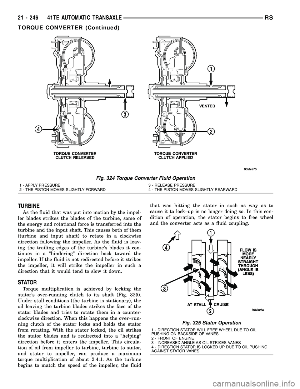
Torque multiplication is achieved by locking the
stator's over-running clutch to its shaft (Fig. 325).
Under stall conditions (the turbine is stationary), the
oil leaving the turbine blades strikes the face of the
stator blades and tries to rotate them in a counter-
clockwise direction. When this happens the over±run-
ning clutch of the stator locks and holds the stator
from rotating. With the stator locked, the oil strikes
the stator blades and is redirected into a ªhelpingº
direction before it enters the impeller. This circula-
tion of oil from impeller to turbine, turbine to stator,
and stator to impeller, can produce a maximum
torque multiplication of about 2.4:1. As the turbine
begins to match the speed of the impeller, the fluidthat was hitting the stator in such as way as to
cause it to lock±up is no longer doing so. In this con-
dition of operation, the stator begins to free wheel
and the converter acts as a fluid coupling.
Fig. 324 Torque Converter Fluid Operation
1 - APPLY PRESSURE 3 - RELEASE PRESSURE
2 - THE PISTON MOVES SLIGHTLY FORWARD 4 - THE PISTON MOVES SLIGHTLY REARWARD
Fig. 325 Stator Operation
1 - DIRECTION STATOR WILL FREE WHEEL DUE TO OIL
PUSHING ON BACKSIDE OF VANES
2 - FRONT OF ENGINE
3 - INCREASED ANGLE AS OIL STRIKES VANES
4 - DIRECTION STATOR IS LOCKED UP DUE TO OIL PUSHING
AGAINST STATOR VANES
21 - 246 41TE AUTOMATIC TRANSAXLERS
TORQUE CONVERTER (Continued)
Page 1930 of 2585

NO. 4 THRUST PLATE CHART
PART NUMBER THICKNESS4431665AB 1.60mm (0.063 in.)
3836237AB 1.73mm (0.068 in.)
4431666AB 1.80mm (0.071 in.)
3836238AB 1.96mm (0.077 in.)
4431667AB 2.03mm (0.080 in.)
3836239AB 2.16mm (0.085 in.)
4431668AB 2.24mm (0.088 in.)
3836240AB 2.39mm (0.094 in.)
4431669AB 2.46mm (0.097 in.)
3836241AB 2.62mm (0.103 in.)
4446670AB 2.67mm (0.105 in.)
4446671AB 2.90mm (0.114 in.)
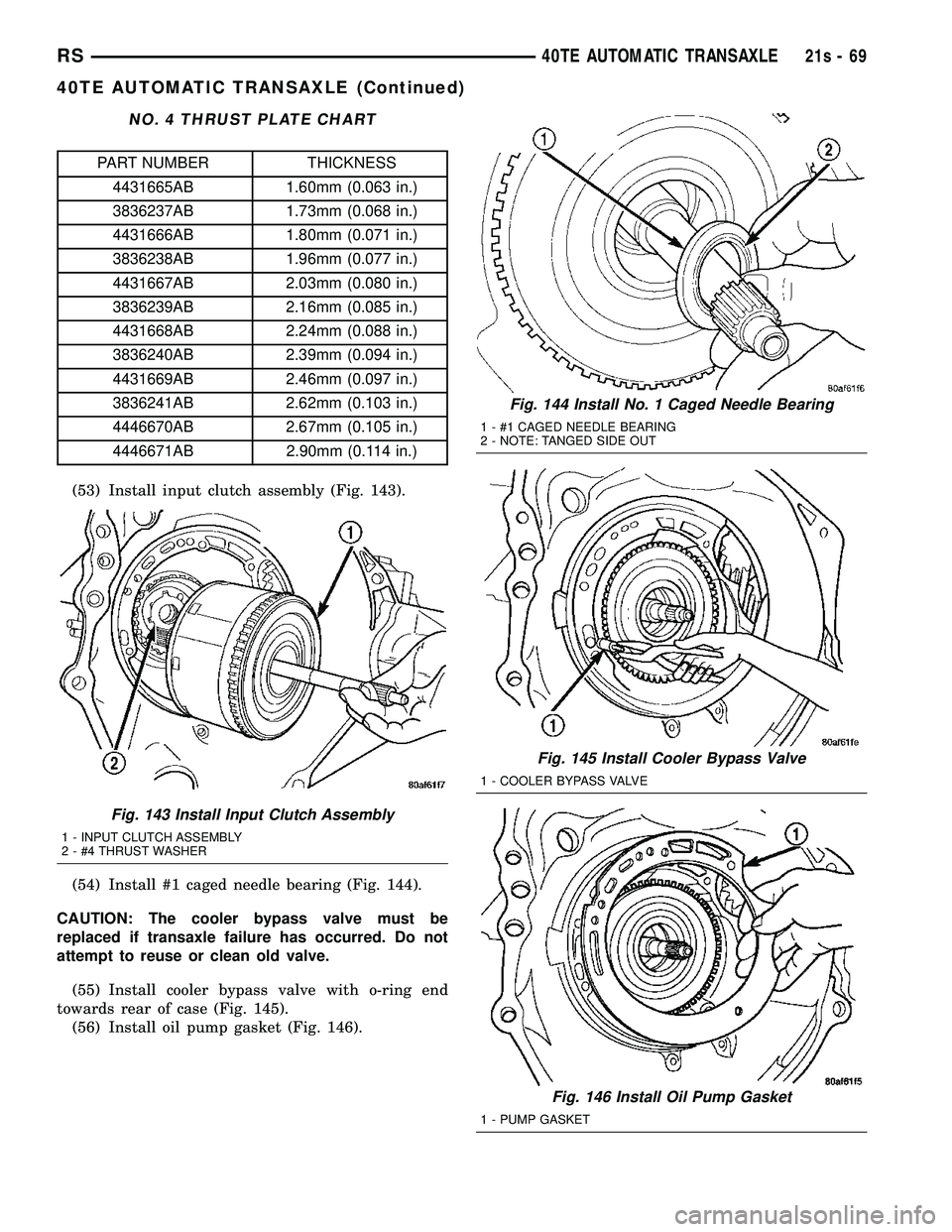
(53) Install input clutch assembly (Fig. 143).
(54) Install #1 caged needle bearing (Fig. 144).
CAUTION: The cooler bypass valve must be
replaced if transaxle failure has occurred. Do not
attempt to reuse or clean old valve. (55) Install cooler bypass valve with o-ring end
towards rear of case (Fig. 145). (56) Install oil pump gasket (Fig. 146).
Fig. 143 Install Input Clutch Assembly
1 - INPUT CLUTCH ASSEMBLY
2 - #4 THRUST WASHER
Fig. 144 Install No. 1 Caged Needle Bearing
1 - #1 CAGED NEEDLE BEARING
2 - NOTE: TANGED SIDE OUT
Fig. 145 Install Cooler Bypass Valve
1 - COOLER BYPASS VALVE
Fig. 146 Install Oil Pump Gasket
1 - PUMP GASKET
RS 40TE AUTOMATIC TRANSAXLE21s-69
40TE AUTOMATIC TRANSAXLE (Continued)
Page 1985 of 2585
(21) Install the OD clutch pack (Fig. 236).
(22) Install OD pressure plate waved snap ring
(Fig. 237). (23) Install the OD/Reverse pressure plate with
large step down (towards OD clutch pack) (Fig. 238).
(24) Install OD pressure plate flat snap ring (Fig.
239) (Fig. 240).
Fig. 236 Install Overdrive Clutch Pack
1 - CLUTCH DISC
2 - CLUTCH PLATE
Fig. 237 Install Waved Snap Ring
1 - OVERDRIVE PRESSURE PLATE WAVED SNAP RING
2 - SCREWDRIVER
Fig. 238 OD/Reverse Reaction Plate
1 - OVERDRIVE/REVERSE PRESSURE PLATE
2 - (STEP SIDE DOWN)
Fig. 239 Install Flat Snap Ring
1 - ARBOR PRESS RAM
2 - TOOL 5059A
3 - FLAT SNAP RING
21s - 124 40TE AUTOMATIC TRANSAXLERS
INPUT CLUTCH ASSEMBLY (Continued)
Page 1987 of 2585

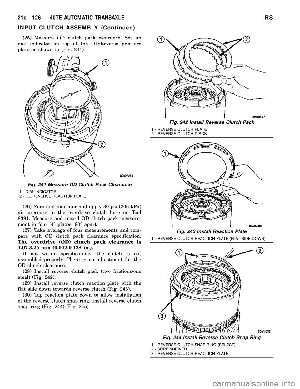
(25) Measure OD clutch pack clearance. Set up
dial indicator on top of the OD/Reverse pressure
plate as shown in (Fig. 241).
(26) Zero dial indicator and apply 30 psi (206 kPa)
air pressure to the overdrive clutch hose on Tool
8391. Measure and record OD clutch pack measure-
ment in four (4) places, 90É apart. (27) Take average of four measurements and com-
pare with OD clutch pack clearance specification.
The overdrive (OD) clutch pack clearance is
1.07-3.25 mm (0.042-0.128 in.). If not within specifications, the clutch is not
assembled properly. There is no adjustment for the
OD clutch clearance. (28) Install reverse clutch pack (two frictions/one
steel) (Fig. 242). (29) Install reverse clutch reaction plate with the
flat side down towards reverse clutch (Fig. 243). (30) Tap reaction plate down to allow installation
of the reverse clutch snap ring. Install reverse clutch
snap ring (Fig. 244) (Fig. 245).
Fig. 241 Measure OD Clutch Pack Clearance
1 - DIAL INDICATOR
2 - OD/REVERSE REACTION PLATE
Fig. 242 Install Reverse Clutch Pack
1 - REVERSE CLUTCH PLATE
2 - REVERSE CLUTCH DISCS
Fig. 243 Install Reaction Plate
1 - REVERSE CLUTCH REACTION PLATE (FLAT SIDE DOWN)
Fig. 244 Install Reverse Clutch Snap Ring
1 - REVERSE CLUTCH SNAP RING (SELECT)
2 - SCREWDRIVER
3 - REVERSE CLUTCH REACTION PLATE
21s - 126 40TE AUTOMATIC TRANSAXLERS
INPUT CLUTCH ASSEMBLY (Continued)