2004 CHRYSLER VOYAGER maintenance
[x] Cancel search: maintenancePage 1595 of 2585
(6) Attach return hose tubes to suspension cradle
crossmember using routing clamp and bolt (Fig. 20).
Tighten clamp bolt to 23 N´m (200 in. lbs.) torque.
(7) Install the power steering fluid cooler on the
cradle crossmember reinforcement (Fig. 23). Install
the mounting bolts and tighten to 11 N´m (100 in.
lbs.). When installing mounting bolts, include pres-
sure hose routing clamp.
(8) Tighten hose tube nut at power steering gear
port to 31 N´m (275 in. lbs.) torque.
(9) Install front emissions vapor canister. (Refer to
25 - EMISSIONS CONTROL/EVAPORATIVE EMIS-
SIONS/VAPOR CANISTER - INSTALLATION)
(10) Lower vehicle.
(11) Install return hose tube into retainer on ABS
bracket (Fig. 20). Close the bracket.
(12) Install return hose onto reservoir (Fig. 21).
Slide the hose clamp into position on fluid reservoir
and attach it.Be sure hose clamp in installed
past bead on fluid reservoir fitting.
(13) Fill and bleed power steering system using
the Power Steering Pump Initial Operation Proce-
dure. (Refer to 19 - STEERING/PUMP - STANDARD
PROCEDURE)
(14) Inspect system for leaks.
HOSE - POWER STEERING
SUPPLY
REMOVAL
REMOVAL - 2.4L ENGINE
(1) Remove filler cap from power steering fluid res-
ervoir.
(2) Using a siphon pump, remove as much power
steering fluid as possible from the power steering
fluid reservoir.
(3) Raise vehicle. (Refer to LUBRICATION &
MAINTENANCE/HOISTING - STANDARD PROCE-
DURE)
(4) Remove hose clamp securing supply hose to
power steering pump, then remove supply hose from
pump fitting.
(5) Lower vehicle.
(6) Remove hose clamp attaching power steering
fluid supply hose to power steering fluid reservoir,
then remove supply hose.
(7) Remove the power steering fluid supply hose
from the vehicle.
REMOVAL - 3.3L/3.8L ENGINE
NOTE: Before proceeding, review all WARNINGS
and CAUTIONS. (Refer to 19 - STEERING/PUMP -WARNING)(Refer to 19 - STEERING/PUMP - CAU-
TION)
(1) Remove cap from power steering fluid reser-
voir.
(2) Using a siphon pump, remove as much power
steering fluid as possible from power steering fluid
reservoir.
(3) Place an oil drain pan under vehicle to catch
any draining power steering fluid.
(4) Remove clamp attaching supply hose to power
steering fluid reservoir. Disconnect hose from reser-
voir (Fig. 21).
(5) Pull upward on hose routing clip releasing it
from bracket on cylinder head cover (Fig. 21).
NOTE: It may be necessary to remove air cleaner
housing to gain greater access to supply hose at
power steering pump. (Refer to 9 - ENGINE/AIR
INTAKE SYSTEM/AIR CLEANER HOUSING -
REMOVAL)
(6) Remove clamp attaching supply hose to power
steering pump. Disconnect hose from pump and
remove from vehicle (Fig. 21).
INSTALLATION
INSTALLATION - 2.4L ENGINE
(1) Install and correctly route power steering fluid
supply hose from remote fluid reservoir to power
steering pump.
(2) Install fluid supply hose onto power steering
fluid reservoir. Install hose clamp.Be sure hose
clamp is installed past bead on fluid reservoir
fitting.
(3) Raise vehicle. (Refer to LUBRICATION &
MAINTENANCE/HOISTING - STANDARD PROCE-
DURE)
(4) Install power steering fluid supply hose on
power steering pump supply fitting. Install hose
clamp.Be sure hose clamp is installed past bead
on pump fitting.
(5) Lower vehicle.
(6) Fill and bleed power steering system using
Power Steering Pump Initial Operation Procedure.
(Refer to 19 - STEERING/PUMP - STANDARD PRO-
CEDURE)
(7) Inspect system for leaks.
INSTALLATION - 3.3L/3.8L ENGINE
(1) Install supply hose onto supply fitting on power
steering pump (Fig. 21). Slide the hose clamp into
position on fluid reservoir and attach it.Be sure
hose clamp in installed past bead on fluid res-
ervoir fitting.
19 - 50 PUMPRS
HOSE - POWER STEERING RETURN (Continued)
Page 1602 of 2585
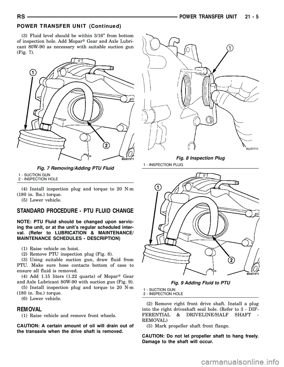
(3) Fluid level should be within 3/16º from bottom
of inspection hole. Add MopartGear and Axle Lubri-
cant 80W-90 as necessary with suitable suction gun
(Fig. 7).
(4) Install inspection plug and torque to 20 N´m
(180 in. lbs.) torque.
(5) Lower vehicle.
STANDARD PROCEDURE - PTU FLUID CHANGE
NOTE: PTU Fluid should be changed upon servic-
ing the unit, or at the unit's regular scheduled inter-
val. (Refer to LUBRICATION & MAINTENANCE/
MAINTENANCE SCHEDULES - DESCRIPTION)
(1) Raise vehicle on hoist.
(2) Remove PTU inspection plug (Fig. 8).
(3) Using suitable suction gun, draw fluid from
PTU. Make sure hose contacts bottom of case to
ensure all fluid is removed.
(4) Add 1.15 liters (1.22 quarts) of MopartGear
and Axle Lubricant 80W-90 with suction gun (Fig. 9).
(5) Install inspection plug and torque to 20 N´m
(180 in. lbs.) torque.
(6) Lower vehicle.
REMOVAL
(1) Raise vehicle and remove front wheels.
CAUTION: A certain amount of oil will drain out of
the transaxle when the drive shaft is removed.(2) Remove right front drive shaft. Install a plug
into the right driveshaft seal hole. (Refer to 3 - DIF-
FERENTIAL & DRIVELINE/HALF SHAFT -
REMOVAL)
(3) Mark propeller shaft front flange.
CAUTION: Do not let propeller shaft to hang freely.
Damage to the shaft will occur.
Fig. 7 Removing/Adding PTU Fluid
1 - SUCTION GUN
2 - INSPECTION HOLE
Fig. 8 Inspection Plug
1 - INSPECTION PLUG
Fig. 9 Adding Fluid to PTU
1 - SUCTION GUN
2 - INSPECTION HOLE
RSPOWER TRANSFER UNIT21-5
POWER TRANSFER UNIT (Continued)
Page 1668 of 2585
If end play measurement indicates a thrust washer
change is necessary, the differential must be disas-
sembled. (Refer to 21 - TRANSMISSION/TRANS-
AXLE/MANUAL/DIFFERENTIAL - DISASSEMBLY)FLUID
STANDARD PROCEDURE
STANDARD PROCEDURE - FLUID LEVEL
CHECK
NOTE: For proper fluid level check intervals, (Refer
to LUBRICATION & MAINTENANCE/MAINTENANCE
SCHEDULES - DESCRIPTION)
The fluid required in this transaxle is Mopart
ATF+4. Use of substitute fluids may result in
improper transaxle operation and/or failure.
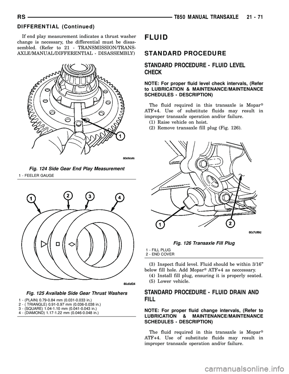
(1) Raise vehicle on hoist.
(2) Remove transaxle fill plug (Fig. 126).
(3) Inspect fluid level. Fluid should be within 3/16º
below fill hole. Add MopartATF+4 as neccessary.
(4) Install fill plug, ensuring it is properly seated.
(5) Lower vehicle.
STANDARD PROCEDURE - FLUID DRAIN AND
FILL
NOTE: For proper fluid change intervals, (Refer to
LUBRICATION & MAINTENANCE/MAINTENANCE
SCHEDULES - DESCRIPTION)
The fluid required in this transaxle is Mopart
ATF+4. Use of substitute fluids may result in
improper transaxle operation and/or failure.
Fig. 124 Side Gear End Play Measurement
1 - FEELER GAUGE
Fig. 125 Available Side Gear Thrust Washers
1 - (PLAIN) 0.79-0.84 mm (0.031-0.033 in.)
2 - ( TRIANGLE) 0.91-0.97 mm (0.036-0.038 in.)
3 - (SQUARE) 1.04-1.10 mm (0.041-0.043 in.)
4 - (DIAMOND) 1.17-1.22 mm (0.046-0.048 in.)
Fig. 126 Transaxle Fill Plug
1 - FILL PLUG
2 - END COVER
RST850 MANUAL TRANSAXLE21-71
DIFFERENTIAL (Continued)
Page 1800 of 2585
STANDARD PROCEDURE - FLUID AND FILTER
SERVICE
NOTE: Refer to the maintenance schedules in
LUBRICATION and MAINTENANCE, or the vehicle
owner's manual, for the recommended maintenance
(fluid/filter change) intervals for this transaxle.
NOTE: Only fluids of the type labeled MoparTATF+4
(Automatic Transmission Fluid) should be used. A
filter change should be made at the time of the
transmission oil change. The magnet (on the inside
of the oil pan) should also be cleaned with a clean,
dry cloth.
NOTE: If the transaxle is disassembled for any rea-
son, the fluid and filter should be changed.
FLUID/FILTER SERVICE (RECOMMENDED)
(1) Raise vehicle on a hoist. Refer to LUBRICA-
TION and MAINTENANCE for proper procedures.
Place a drain container with a large opening, under
transaxle oil pan.
(2) Loosen pan bolts and tap the pan at one corner
to break it loose allowing fluid to drain, then remove
the oil pan.
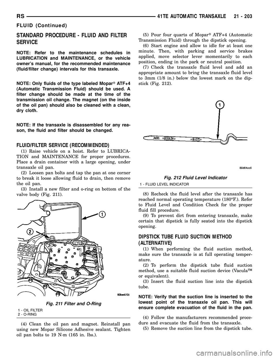
(3) Install a new filter and o-ring on bottom of the
valve body (Fig. 211).
(4) Clean the oil pan and magnet. Reinstall pan
using new Mopar Silicone Adhesive sealant. Tighten
oil pan bolts to 19 N´m (165 in. lbs.).(5) Pour four quarts of MopartATF+4 (Automatic
Transmission Fluid) through the dipstick opening.
(6) Start engine and allow to idle for at least one
minute. Then, with parking and service brakes
applied, move selector lever momentarily to each
position, ending in the park or neutral position.
(7) Check the transaxle fluid level and add an
appropriate amount to bring the transaxle fluid level
to 3mm (1/8 in.) below the lowest mark on the dip-
stick (Fig. 212).
(8) Recheck the fluid level after the transaxle has
reached normal operating temperature (180ÉF.). Refer
to Fluid Level and Condition Check for the proper
fluid fill procedure.
(9) To prevent dirt from entering transaxle, make
certain that dipstick is fully seated into the dipstick
opening.
DIPSTICK TUBE FLUID SUCTION METHOD
(ALTERNATIVE)
(1) When performing the fluid suction method,
make sure the transaxle is at full operating temper-
ature.
(2) To perform the dipstick tube fluid suction
method, use a suitable fluid suction device (VaculaŸ
or equivalent).
(3) Insert the fluid suction line into the dipstick
tube.
NOTE: Verify that the suction line is inserted to the
lowest point of the transaxle oil pan. This will
ensure complete evacuation of the fluid in the pan.
(4) Follow the manufacturers recommended proce-
dure and evacuate the fluid from the transaxle.
(5) Remove the suction line from the dipstick tube.
Fig. 211 Filter and O-Ring
1 - OIL FILTER
2 - O-RING
Fig. 212 Fluid Level Indicator
1 - FLUID LEVEL INDICATOR
RS41TE AUTOMATIC TRANSAXLE21 - 203
FLUID (Continued)
Page 1965 of 2585

STANDARD PROCEDURE - FLUID AND FILTER
SERVICE
NOTE: Refer to the maintenance schedules in
LUBRICATION and MAINTENANCE, or the vehicle
owner's manual, for the recommended maintenance
(fluid/filter change) intervals for this transaxle.
NOTE: Only fluids of the type labeled MoparTATF+4
should be used. A filter change should be made at
the time of the transmission oil change. The magnet
(on the inside of the oil pan) should also be cleaned
with a clean, dry cloth.
NOTE: If the transaxle is disassembled for any rea-
son, the fluid and filter should be changed.
FLUID/FILTER SERVICE (RECOMMENDED)
(1) Raise vehicle on a hoist. Refer to LUBRICA-
TION and MAINTENANCE for proper procedures.
Place a drain container with a large opening, under
transaxle oil pan. (2) Remove both engine mount-to-engine cross-
member cradle nuts. Using suitable screw jack and
wood block, raise engine and transmission slightly to
facilitate transaxle oil pan removal and installation. (3) Loosen pan bolts and tap the pan at one corner
to break it loose allowing fluid to drain, then remove
the oil pan. (4) Install a new filter and o-ring on bottom of the
valve body (Fig. 189). (5) Clean the oil pan and magnet. Reinstall pan
using new Mopar Silicone Adhesive sealant. Tighten
oil pan bolts to 19 N´m (165 in. lbs.). (6) Pour four quarts of Mopar tATF+4 through the
dipstick opening. (7) Start engine and allow to idle for at least one
minute. Then, with parking and service brakes
applied, move selector lever momentarily to each
position, ending in the park or neutral position. (8) Check the transaxle fluid level and add an
appropriate amount to bring the transaxle fluid level
to 3mm (1/8 in.) below the lowest mark on the dip-
stick (Fig. 190).
(9) Recheck the fluid level after the transaxle has
reached normal operating temperature (180ÉF.). Refer
to Fluid Level and Condition Check for the proper
fluid fill procedure. (10) To prevent dirt from entering transaxle, make
certain that dipstick is fully seated into the dipstick
opening.
DIPSTICK TUBE FLUID SUCTION METHOD
(ALTERNATIVE)
(1) When performing the fluid suction method,
make sure the transaxle is at full operating temper-
ature. (2) To perform the dipstick tube fluid suction
method, use a suitable fluid suction device (VaculaŸ
or equivalent). (3) Insert the fluid suction line into the dipstick
tube.
NOTE: Verify that the suction line is inserted to the
lowest point of the transaxle oil pan. This will
ensure complete evacuation of the fluid in the pan.
(4) Follow the manufacturers recommended proce-
dure and evacuate the fluid from the transaxle.
Fig. 189 Filter and O-Ring
1 - OIL FILTER
2 - O-RING
Fig. 190 Fluid Level Indicator
1 - FLUID LEVEL INDICATOR
21s - 104 40TE AUTOMATIC TRANSAXLERS
FLUID (Continued)
Page 2080 of 2585
TIRES/WHEELS
TABLE OF CONTENTS
page page
TIRES/WHEELS
DIAGNOSIS AND TESTING - TIRE AND
WHEEL VIBRATION.....................1
STANDARD PROCEDURE
STANDARD PROCEDURE - TIRE AND
WHEEL BALANCE......................5
STANDARD PROCEDURE - TIRE AND
WHEEL MATCH MOUNTING..............7
STANDARD PROCEDURE - TIRE AND
WHEEL ROTATION.....................7
REMOVAL
REMOVAL - TIRE AND WHEEL ASSEMBLY
(ALUMINUM WHEEL)....................7
REMOVAL - TIRE AND WHEEL ASSEMBLY
(STEEL WHEEL).......................8
INSTALLATION
INSTALLATION - TIRE AND WHEEL
ASSEMBLY (ALUMINUM WHEEL)..........8
INSTALLATION - TIRE AND WHEEL
ASSEMBLY (STEEL WHEEL)..............8
TIRE PRESSURE MONITORING
DESCRIPTION..........................9
OPERATION............................9
SENSOR - TPM
DESCRIPTION.........................10
OPERATION...........................10
CAUTION.............................10
DIAGNOSIS AND TESTING - TIRE PRESSURE
SENSOR............................10
STANDARD PROCEDURE - TIRE PRESSURE
SENSOR RETRAIN....................10
REMOVAL.............................11
INSTALLATION.........................12
TIRES
DESCRIPTION
DESCRIPTION - TIRE..................13
DESCRIPTION - RADIAL-PLY TIRES.......14DESCRIPTION - REPLACEMENT TIRES....14
DESCRIPTION - SPARE TIRE
(TEMPORARY).......................14
DIAGNOSIS AND TESTING
DIAGNOSIS AND TESTING - TIRE NOISE . . . 14
DIAGNOSIS AND TESTING - TIRE/VEHICLE
LEAD...............................14
DIAGNOSIS AND TESTING - TIRE WEAR
PATTERNS..........................16
DIAGNOSIS AND TESTING - TREAD WEAR
INDICATORS.........................16
STANDARD PROCEDURE
STANDARD PROCEDURE - TIRE INFLATION
PRESSURES.........................16
STANDARD PROCEDURE - TIRE
PRESSURE FOR HIGH SPEED
OPERATION.........................17
STANDARD PROCEDURE - TIRE LEAK
REPAIRING..........................17
CLEANING - TIRES.....................17
WHEELS
DESCRIPTION - WHEEL..................18
DIAGNOSIS AND TESTING - WHEEL
INSPECTION.........................18
CLEANING - ALUMINUM WHEEL CARE......18
SPECIFICATIONS
WHEEL.............................19
WHEEL COVER
DESCRIPTION.........................19
REMOVAL.............................19
INSTALLATION.........................19
WHEEL MOUNTING STUDS - FRONT
REMOVAL.............................20
INSTALLATION.........................21
WHEEL MOUNTING STUDS - REAR
REMOVAL.............................21
INSTALLATION.........................22
TIRES/WHEELS
DIAGNOSIS AND TESTING - TIRE AND WHEEL
VIBRATION
Tire and wheel imbalance, runout and force varia-
tion can cause vehicles to exhibit steering wheel
vibration.
VISUAL INSPECTION
Visual inspection of the vehicle is recommended
prior to road testing or performing any other proce-
dure. Raise vehicle on a suitable hoist. (Refer to
LUBRICATION & MAINTENANCE/HOISTING -
STANDARD PROCEDURE)
Inspect for the following:
²Verify correct (OEM) wheel and tire, as well as
correct wheel weights. Aluminum wheels require
RSTIRES/WHEELS22-1
Page 2081 of 2585
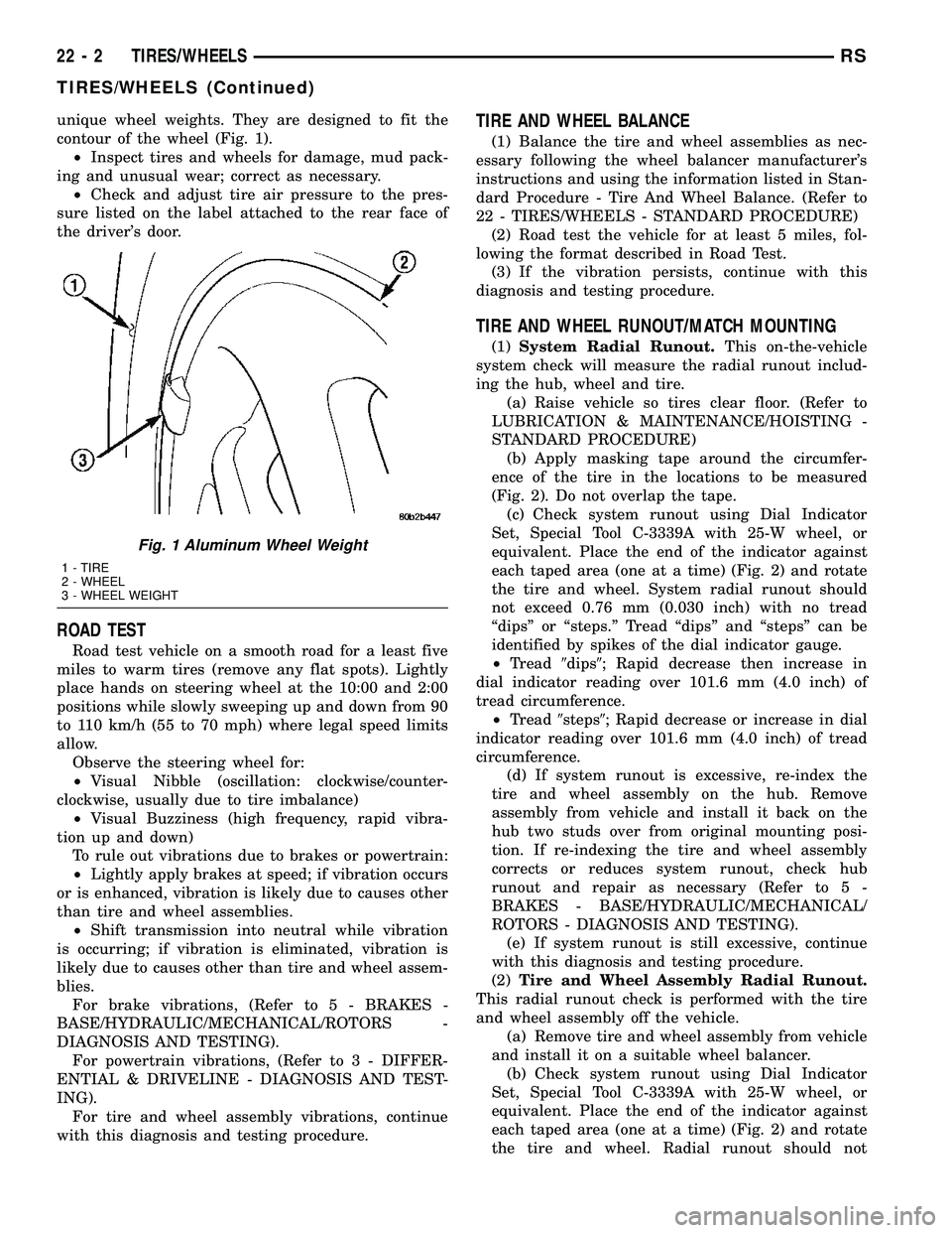
unique wheel weights. They are designed to fit the
contour of the wheel (Fig. 1).
²Inspect tires and wheels for damage, mud pack-
ing and unusual wear; correct as necessary.
²Check and adjust tire air pressure to the pres-
sure listed on the label attached to the rear face of
the driver's door.
ROAD TEST
Road test vehicle on a smooth road for a least five
miles to warm tires (remove any flat spots). Lightly
place hands on steering wheel at the 10:00 and 2:00
positions while slowly sweeping up and down from 90
to 110 km/h (55 to 70 mph) where legal speed limits
allow.
Observe the steering wheel for:
²Visual Nibble (oscillation: clockwise/counter-
clockwise, usually due to tire imbalance)
²Visual Buzziness (high frequency, rapid vibra-
tion up and down)
To rule out vibrations due to brakes or powertrain:
²Lightly apply brakes at speed; if vibration occurs
or is enhanced, vibration is likely due to causes other
than tire and wheel assemblies.
²Shift transmission into neutral while vibration
is occurring; if vibration is eliminated, vibration is
likely due to causes other than tire and wheel assem-
blies.
For brake vibrations, (Refer to 5 - BRAKES -
BASE/HYDRAULIC/MECHANICAL/ROTORS -
DIAGNOSIS AND TESTING).
For powertrain vibrations, (Refer to 3 - DIFFER-
ENTIAL & DRIVELINE - DIAGNOSIS AND TEST-
ING).
For tire and wheel assembly vibrations, continue
with this diagnosis and testing procedure.
TIRE AND WHEEL BALANCE
(1) Balance the tire and wheel assemblies as nec-
essary following the wheel balancer manufacturer's
instructions and using the information listed in Stan-
dard Procedure - Tire And Wheel Balance. (Refer to
22 - TIRES/WHEELS - STANDARD PROCEDURE)
(2) Road test the vehicle for at least 5 miles, fol-
lowing the format described in Road Test.
(3) If the vibration persists, continue with this
diagnosis and testing procedure.
TIRE AND WHEEL RUNOUT/MATCH MOUNTING
(1)System Radial Runout.This on-the-vehicle
system check will measure the radial runout includ-
ing the hub, wheel and tire.
(a) Raise vehicle so tires clear floor. (Refer to
LUBRICATION & MAINTENANCE/HOISTING -
STANDARD PROCEDURE)
(b) Apply masking tape around the circumfer-
ence of the tire in the locations to be measured
(Fig. 2). Do not overlap the tape.
(c) Check system runout using Dial Indicator
Set, Special Tool C-3339A with 25-W wheel, or
equivalent. Place the end of the indicator against
each taped area (one at a time) (Fig. 2) and rotate
the tire and wheel. System radial runout should
not exceed 0.76 mm (0.030 inch) with no tread
ªdipsº or ªsteps.º Tread ªdipsº and ªstepsº can be
identified by spikes of the dial indicator gauge.
²Tread9dips9; Rapid decrease then increase in
dial indicator reading over 101.6 mm (4.0 inch) of
tread circumference.
²Tread9steps9; Rapid decrease or increase in dial
indicator reading over 101.6 mm (4.0 inch) of tread
circumference.
(d) If system runout is excessive, re-index the
tire and wheel assembly on the hub. Remove
assembly from vehicle and install it back on the
hub two studs over from original mounting posi-
tion. If re-indexing the tire and wheel assembly
corrects or reduces system runout, check hub
runout and repair as necessary (Refer to 5 -
BRAKES - BASE/HYDRAULIC/MECHANICAL/
ROTORS - DIAGNOSIS AND TESTING).
(e) If system runout is still excessive, continue
with this diagnosis and testing procedure.
(2)Tire and Wheel Assembly Radial Runout.
This radial runout check is performed with the tire
and wheel assembly off the vehicle.
(a) Remove tire and wheel assembly from vehicle
and install it on a suitable wheel balancer.
(b) Check system runout using Dial Indicator
Set, Special Tool C-3339A with 25-W wheel, or
equivalent. Place the end of the indicator against
each taped area (one at a time) (Fig. 2) and rotate
the tire and wheel. Radial runout should not
Fig. 1 Aluminum Wheel Weight
1 - TIRE
2 - WHEEL
3 - WHEEL WEIGHT
22 - 2 TIRES/WHEELSRS
TIRES/WHEELS (Continued)
Page 2099 of 2585
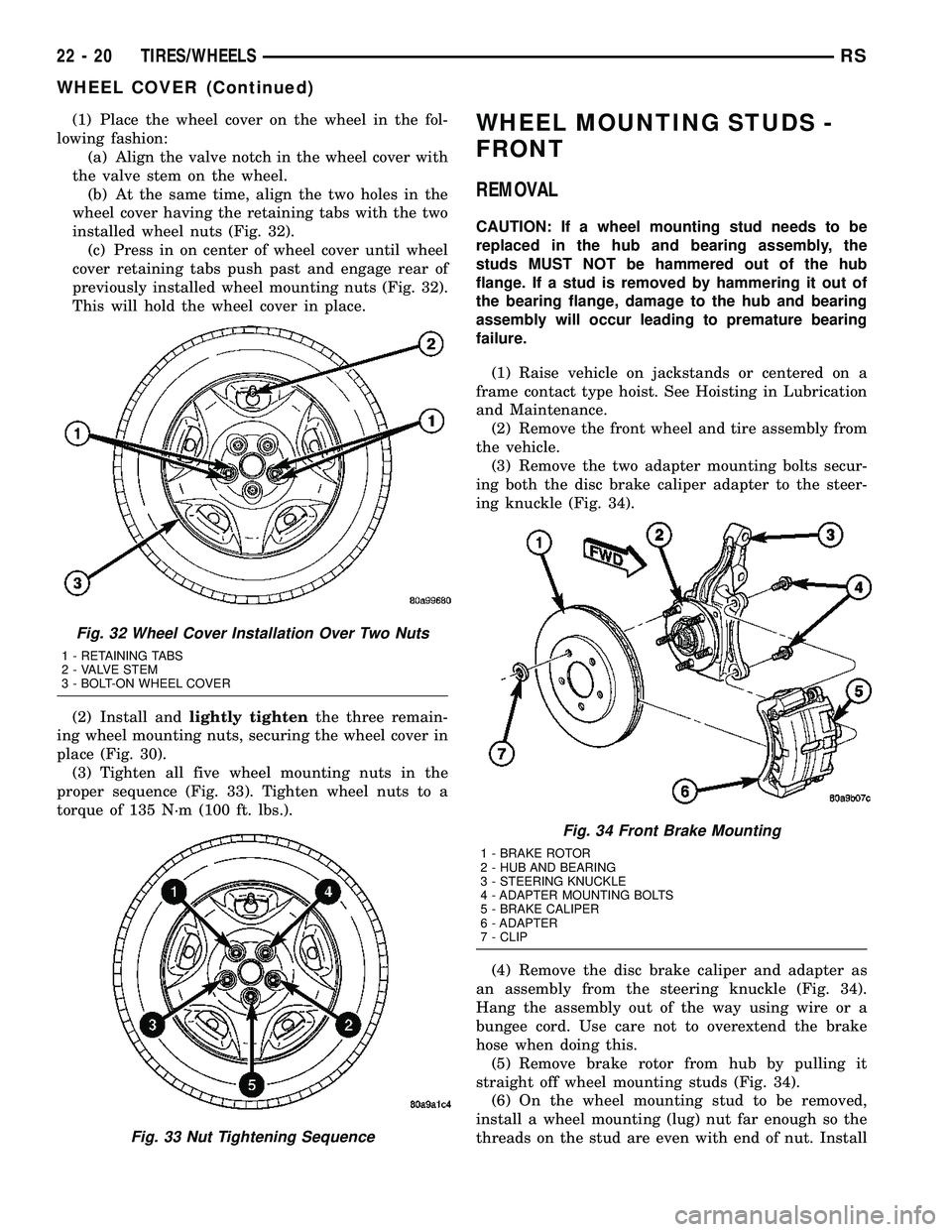
(1) Place the wheel cover on the wheel in the fol-
lowing fashion:
(a) Align the valve notch in the wheel cover with
the valve stem on the wheel.
(b) At the same time, align the two holes in the
wheel cover having the retaining tabs with the two
installed wheel nuts (Fig. 32).
(c) Press in on center of wheel cover until wheel
cover retaining tabs push past and engage rear of
previously installed wheel mounting nuts (Fig. 32).
This will hold the wheel cover in place.
(2) Install andlightly tightenthe three remain-
ing wheel mounting nuts, securing the wheel cover in
place (Fig. 30).
(3) Tighten all five wheel mounting nuts in the
proper sequence (Fig. 33). Tighten wheel nuts to a
torque of 135 N´m (100 ft. lbs.).WHEEL MOUNTING STUDS -
FRONT
REMOVAL
CAUTION: If a wheel mounting stud needs to be
replaced in the hub and bearing assembly, the
studs MUST NOT be hammered out of the hub
flange. If a stud is removed by hammering it out of
the bearing flange, damage to the hub and bearing
assembly will occur leading to premature bearing
failure.
(1) Raise vehicle on jackstands or centered on a
frame contact type hoist. See Hoisting in Lubrication
and Maintenance.
(2) Remove the front wheel and tire assembly from
the vehicle.
(3) Remove the two adapter mounting bolts secur-
ing both the disc brake caliper adapter to the steer-
ing knuckle (Fig. 34).
(4) Remove the disc brake caliper and adapter as
an assembly from the steering knuckle (Fig. 34).
Hang the assembly out of the way using wire or a
bungee cord. Use care not to overextend the brake
hose when doing this.
(5) Remove brake rotor from hub by pulling it
straight off wheel mounting studs (Fig. 34).
(6) On the wheel mounting stud to be removed,
install a wheel mounting (lug) nut far enough so the
threads on the stud are even with end of nut. Install
Fig. 32 Wheel Cover Installation Over Two Nuts
1 - RETAINING TABS
2 - VALVE STEM
3 - BOLT-ON WHEEL COVER
Fig. 33 Nut Tightening Sequence
Fig. 34 Front Brake Mounting
1 - BRAKE ROTOR
2 - HUB AND BEARING
3 - STEERING KNUCKLE
4 - ADAPTER MOUNTING BOLTS
5 - BRAKE CALIPER
6 - ADAPTER
7 - CLIP
22 - 20 TIRES/WHEELSRS
WHEEL COVER (Continued)