2004 CHRYSLER VOYAGER brake rotor
[x] Cancel search: brake rotorPage 319 of 2585

(c) Install secondary (yellow) retaining clip over
wheel speed sensor head and engage the tabs on
each side.
(15) Install the park brake cable into its mounting
hole in the adapter. Be sure all the locking tabs
on the park brake cable retainer are expanded
out to ensure the cable will not pull out of the
adapter. (16) Install the end of the park brake cable on the
park brake actuator lever (Fig. 121). (17) Attach park brake cable to adapter using
mounting bolt. (18) Remove the locking pliers (Fig. 117) from the
front park brake cable. (19) Adjust the park brake drum-in-hat brake
shoes. (Refer t o 5 - BRAKES/PARKING BRAKE/
SHOES - ADJUSTMENTS). (20) Install the rotor on the hub/bearing.
(21) Carefully lower caliper and brake shoes over
rotor and onto the adapter using the reverse proce-
dure for removal (Fig. 119).
CAUTION: When installing guide pin bolts extreme
caution should be taken not to crossthread the cal-
iper guide pin bolts.
(22) Install the caliper guide pin bolts (Fig. 118).
Tighten the guide pin bolts to a torque of 35 N´m (26
ft. lbs.). (23) AWD only - Clean all foreign material off the
threads of the outer C/V joint stub shaft. Install the
washer and hub nut (Fig. 116) on the stub shaft of
the outer C/V joint. (24) AWD only - Set the parking brake.
(25) AWD only - Tighten the hub nut to a torque of
244 N´m (180 ft. lbs.). (26) AWD only - Install the spring washer (Fig.
115) on the stub shaft of the outer C/V joint. (27) AWD only - Install the nut retainer and cotter
pin (Fig. 114) on the stub shaft of the outer C/V joint. (28) Install the wheel and tire assembly. Tighten
the wheel mounting stud nuts in proper sequence
until all nuts are torqued to half specification. Then
repeat the tightening sequence to the full specified
torque of 135 N´m (100 ft. lbs.). (29) Lower vehicle.
(30) Fully apply and release the park brake pedal
one time. This will seat and correctly adjust the park
brake cables.
CAUTION: Before moving vehicle, pump the brake
pedal several times to insure the vehicle has a firm
brake pedal to adequately stop vehicle.
(31) Road test the vehicle and make several stops
to wear off any foreign material on the brakes and to
seat the brake shoe linings.ADJUSTMENTS
ADJUSTMENT - PARKING BRAKE SHOES
CAUTION: Before adjusting the park brake shoes be
sure that the park brake pedal is in the fully
released position. If park brake pedal is not in the
fully released position, the park brake shoes can
not be accurately adjusted.
(1) Raise vehicle.
(2) Remove tire and wheel.
(3) Remove disc brake caliper from caliper adapter
(Fig. 136). (Refer t o 5 - BRAKES/HYDRAULIC/ME-
CHANICAL/DISC BRAKE CALIPERS - REMOVAL).
(4) Remove rotor from hub/bearing.
NOTE: When measuring the brake drum diameter,
the diameter should be measured in the center of
the area in which the park brake shoes contact the
surface of the brake drum. (5) Using Brake Shoe Gauge, Special Tool C-3919,
or equivalent, accuratelymeasure the inside diam-
eter of the park brake drum portion of the rotor (Fig.
137). (6) Using a ruler that reads in 64th of an inch,
accurately read the measurement of the inside diam-
eter of the park brake drum from the special tool
(Fig. 138).
Fig. 136 Disc Brake Caliper
1 - DISC BRAKE CALIPER
2 - ADAPTER
3 - AXLE
4 - GUIDE PIN BOLTS
5 - DRIVESHAFT (AWD MODELS ONLY)
5s - 76 BRAKESRS
SHOES - PARKING BRAKE (Continued)
Page 320 of 2585

(7) Reduce the inside diameter measurement of
the brake drum that was taken using Special Tool
C-3919 by 1/64 of an inch. Reset Gauge, Brake Shoe,
Special Tool C-3919 or the equivalent used, so that
the outside measurement jaws are set to the reduced
measurement (Fig. 139). (8) Place Gauge, Brake Shoe, Special Tool C-3919,
or equivalent over the park brake shoes. The special
tool must be located diagonally across at the top of
one shoe and bottom of opposite shoe (widest point)
of the park brake shoes. (9) Using the star wheel adjuster, adjust the park
brake shoes until the lining on the park brake shoes
just touches the jaws on the special tool. (10) Repeat step 8 above and measure shoes in
both directions. (11) Install brake rotor on hub and bearing.
(12) Rotate rotor to verify that the park brake
shoes are not dragging on the brake drum. If park
brake shoes are dragging, remove rotor and back off
star wheel adjuster one notch and recheck for brake
shoe drag against drum. Continue with the previous
step until brake shoes are not dragging on brake
drum. (13) Install disc brake caliper on caliper adapter
(Fig. 136). (Refer t o 5 - BRAKES/HYDRAULIC/ME-
CHANICAL/DISC BRAKE CALIPERS - INSTALLA-
TION). (14) Install wheel and tire.
(15) Tighten the wheel mounting nuts in the
proper sequence until all nuts are torqued to half the
specified torque. Then repeat the tightening sequence
to the full specified torque of 135 N´m (100 ft. lbs.). (16) Lower vehicle.
(17) Apply and release the park brake pedal one
time. This will seat and correctly adjust the park
brake cables.
CAUTION: Before moving vehicle, pump brake
pedal several times to ensure the vehicle has a firm
enough pedal to stop the vehicle.
(18) Road test the vehicle to ensure proper func-
tion of the vehicle's brake system.
Fig. 137 Measuring Park Brake Drum Diameter
Fig. 138 Reading Park Brake Drum Diameter
1 - SPECIAL TOOL C-3919
2 - RULER
Fig. 139 Setting Gauge To Park Brake Shoe Measurement
1 - RULER
2 - SPECIAL TOOL C-3919
RS BRAKES5s-77
SHOES - PARKING BRAKE (Continued)
Page 2081 of 2585
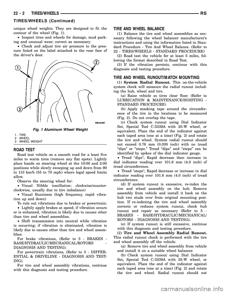
unique wheel weights. They are designed to fit the
contour of the wheel (Fig. 1).
²Inspect tires and wheels for damage, mud pack-
ing and unusual wear; correct as necessary.
²Check and adjust tire air pressure to the pres-
sure listed on the label attached to the rear face of
the driver's door.
ROAD TEST
Road test vehicle on a smooth road for a least five
miles to warm tires (remove any flat spots). Lightly
place hands on steering wheel at the 10:00 and 2:00
positions while slowly sweeping up and down from 90
to 110 km/h (55 to 70 mph) where legal speed limits
allow.
Observe the steering wheel for:
²Visual Nibble (oscillation: clockwise/counter-
clockwise, usually due to tire imbalance)
²Visual Buzziness (high frequency, rapid vibra-
tion up and down)
To rule out vibrations due to brakes or powertrain:
²Lightly apply brakes at speed; if vibration occurs
or is enhanced, vibration is likely due to causes other
than tire and wheel assemblies.
²Shift transmission into neutral while vibration
is occurring; if vibration is eliminated, vibration is
likely due to causes other than tire and wheel assem-
blies.
For brake vibrations, (Refer to 5 - BRAKES -
BASE/HYDRAULIC/MECHANICAL/ROTORS -
DIAGNOSIS AND TESTING).
For powertrain vibrations, (Refer to 3 - DIFFER-
ENTIAL & DRIVELINE - DIAGNOSIS AND TEST-
ING).
For tire and wheel assembly vibrations, continue
with this diagnosis and testing procedure.
TIRE AND WHEEL BALANCE
(1) Balance the tire and wheel assemblies as nec-
essary following the wheel balancer manufacturer's
instructions and using the information listed in Stan-
dard Procedure - Tire And Wheel Balance. (Refer to
22 - TIRES/WHEELS - STANDARD PROCEDURE)
(2) Road test the vehicle for at least 5 miles, fol-
lowing the format described in Road Test.
(3) If the vibration persists, continue with this
diagnosis and testing procedure.
TIRE AND WHEEL RUNOUT/MATCH MOUNTING
(1)System Radial Runout.This on-the-vehicle
system check will measure the radial runout includ-
ing the hub, wheel and tire.
(a) Raise vehicle so tires clear floor. (Refer to
LUBRICATION & MAINTENANCE/HOISTING -
STANDARD PROCEDURE)
(b) Apply masking tape around the circumfer-
ence of the tire in the locations to be measured
(Fig. 2). Do not overlap the tape.
(c) Check system runout using Dial Indicator
Set, Special Tool C-3339A with 25-W wheel, or
equivalent. Place the end of the indicator against
each taped area (one at a time) (Fig. 2) and rotate
the tire and wheel. System radial runout should
not exceed 0.76 mm (0.030 inch) with no tread
ªdipsº or ªsteps.º Tread ªdipsº and ªstepsº can be
identified by spikes of the dial indicator gauge.
²Tread9dips9; Rapid decrease then increase in
dial indicator reading over 101.6 mm (4.0 inch) of
tread circumference.
²Tread9steps9; Rapid decrease or increase in dial
indicator reading over 101.6 mm (4.0 inch) of tread
circumference.
(d) If system runout is excessive, re-index the
tire and wheel assembly on the hub. Remove
assembly from vehicle and install it back on the
hub two studs over from original mounting posi-
tion. If re-indexing the tire and wheel assembly
corrects or reduces system runout, check hub
runout and repair as necessary (Refer to 5 -
BRAKES - BASE/HYDRAULIC/MECHANICAL/
ROTORS - DIAGNOSIS AND TESTING).
(e) If system runout is still excessive, continue
with this diagnosis and testing procedure.
(2)Tire and Wheel Assembly Radial Runout.
This radial runout check is performed with the tire
and wheel assembly off the vehicle.
(a) Remove tire and wheel assembly from vehicle
and install it on a suitable wheel balancer.
(b) Check system runout using Dial Indicator
Set, Special Tool C-3339A with 25-W wheel, or
equivalent. Place the end of the indicator against
each taped area (one at a time) (Fig. 2) and rotate
the tire and wheel. Radial runout should not
Fig. 1 Aluminum Wheel Weight
1 - TIRE
2 - WHEEL
3 - WHEEL WEIGHT
22 - 2 TIRES/WHEELSRS
TIRES/WHEELS (Continued)
Page 2099 of 2585
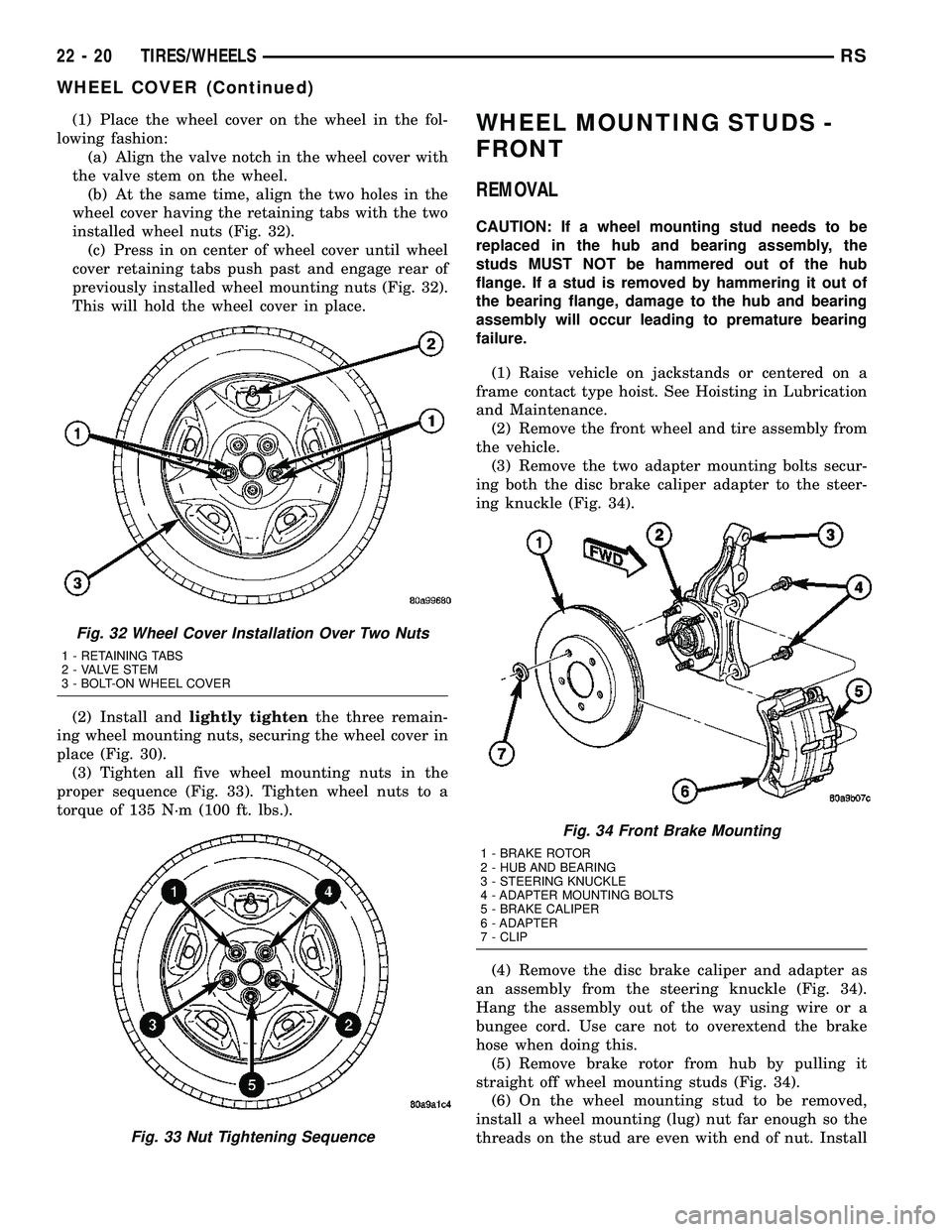
(1) Place the wheel cover on the wheel in the fol-
lowing fashion:
(a) Align the valve notch in the wheel cover with
the valve stem on the wheel.
(b) At the same time, align the two holes in the
wheel cover having the retaining tabs with the two
installed wheel nuts (Fig. 32).
(c) Press in on center of wheel cover until wheel
cover retaining tabs push past and engage rear of
previously installed wheel mounting nuts (Fig. 32).
This will hold the wheel cover in place.
(2) Install andlightly tightenthe three remain-
ing wheel mounting nuts, securing the wheel cover in
place (Fig. 30).
(3) Tighten all five wheel mounting nuts in the
proper sequence (Fig. 33). Tighten wheel nuts to a
torque of 135 N´m (100 ft. lbs.).WHEEL MOUNTING STUDS -
FRONT
REMOVAL
CAUTION: If a wheel mounting stud needs to be
replaced in the hub and bearing assembly, the
studs MUST NOT be hammered out of the hub
flange. If a stud is removed by hammering it out of
the bearing flange, damage to the hub and bearing
assembly will occur leading to premature bearing
failure.
(1) Raise vehicle on jackstands or centered on a
frame contact type hoist. See Hoisting in Lubrication
and Maintenance.
(2) Remove the front wheel and tire assembly from
the vehicle.
(3) Remove the two adapter mounting bolts secur-
ing both the disc brake caliper adapter to the steer-
ing knuckle (Fig. 34).
(4) Remove the disc brake caliper and adapter as
an assembly from the steering knuckle (Fig. 34).
Hang the assembly out of the way using wire or a
bungee cord. Use care not to overextend the brake
hose when doing this.
(5) Remove brake rotor from hub by pulling it
straight off wheel mounting studs (Fig. 34).
(6) On the wheel mounting stud to be removed,
install a wheel mounting (lug) nut far enough so the
threads on the stud are even with end of nut. Install
Fig. 32 Wheel Cover Installation Over Two Nuts
1 - RETAINING TABS
2 - VALVE STEM
3 - BOLT-ON WHEEL COVER
Fig. 33 Nut Tightening Sequence
Fig. 34 Front Brake Mounting
1 - BRAKE ROTOR
2 - HUB AND BEARING
3 - STEERING KNUCKLE
4 - ADAPTER MOUNTING BOLTS
5 - BRAKE CALIPER
6 - ADAPTER
7 - CLIP
22 - 20 TIRES/WHEELSRS
WHEEL COVER (Continued)
Page 2100 of 2585
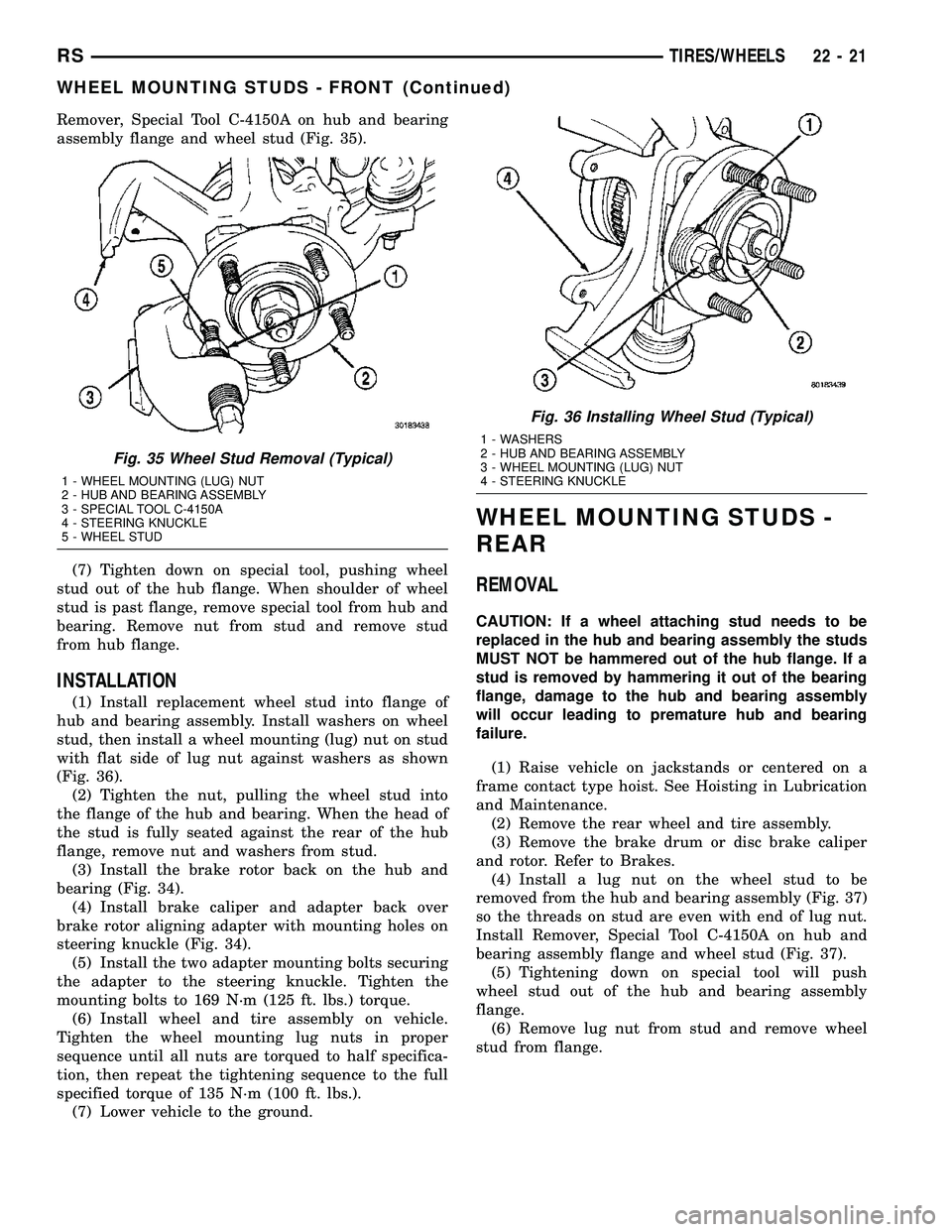
Remover, Special Tool C-4150A on hub and bearing
assembly flange and wheel stud (Fig. 35).
(7) Tighten down on special tool, pushing wheel
stud out of the hub flange. When shoulder of wheel
stud is past flange, remove special tool from hub and
bearing. Remove nut from stud and remove stud
from hub flange.
INSTALLATION
(1) Install replacement wheel stud into flange of
hub and bearing assembly. Install washers on wheel
stud, then install a wheel mounting (lug) nut on stud
with flat side of lug nut against washers as shown
(Fig. 36).
(2) Tighten the nut, pulling the wheel stud into
the flange of the hub and bearing. When the head of
the stud is fully seated against the rear of the hub
flange, remove nut and washers from stud.
(3) Install the brake rotor back on the hub and
bearing (Fig. 34).
(4) Install brake caliper and adapter back over
brake rotor aligning adapter with mounting holes on
steering knuckle (Fig. 34).
(5) Install the two adapter mounting bolts securing
the adapter to the steering knuckle. Tighten the
mounting bolts to 169 N´m (125 ft. lbs.) torque.
(6) Install wheel and tire assembly on vehicle.
Tighten the wheel mounting lug nuts in proper
sequence until all nuts are torqued to half specifica-
tion, then repeat the tightening sequence to the full
specified torque of 135 N´m (100 ft. lbs.).
(7) Lower vehicle to the ground.
WHEEL MOUNTING STUDS -
REAR
REMOVAL
CAUTION: If a wheel attaching stud needs to be
replaced in the hub and bearing assembly the studs
MUST NOT be hammered out of the hub flange. If a
stud is removed by hammering it out of the bearing
flange, damage to the hub and bearing assembly
will occur leading to premature hub and bearing
failure.
(1) Raise vehicle on jackstands or centered on a
frame contact type hoist. See Hoisting in Lubrication
and Maintenance.
(2) Remove the rear wheel and tire assembly.
(3) Remove the brake drum or disc brake caliper
and rotor. Refer to Brakes.
(4) Install a lug nut on the wheel stud to be
removed from the hub and bearing assembly (Fig. 37)
so the threads on stud are even with end of lug nut.
Install Remover, Special Tool C-4150A on hub and
bearing assembly flange and wheel stud (Fig. 37).
(5) Tightening down on special tool will push
wheel stud out of the hub and bearing assembly
flange.
(6) Remove lug nut from stud and remove wheel
stud from flange.
Fig. 35 Wheel Stud Removal (Typical)
1 - WHEEL MOUNTING (LUG) NUT
2 - HUB AND BEARING ASSEMBLY
3 - SPECIAL TOOL C-4150A
4 - STEERING KNUCKLE
5 - WHEEL STUD
Fig. 36 Installing Wheel Stud (Typical)
1 - WASHERS
2 - HUB AND BEARING ASSEMBLY
3 - WHEEL MOUNTING (LUG) NUT
4 - STEERING KNUCKLE
RSTIRES/WHEELS22-21
WHEEL MOUNTING STUDS - FRONT (Continued)
Page 2101 of 2585
INSTALLATION
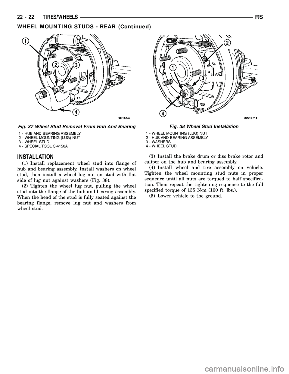
(1) Install replacement wheel stud into flange of
hub and bearing assembly. Install washers on wheel
stud, then install a wheel lug nut on stud with flat
side of lug nut against washers (Fig. 38).
(2) Tighten the wheel lug nut, pulling the wheel
stud into the flange of the hub and bearing assembly.
When the head of the stud is fully seated against the
bearing flange, remove lug nut and washers from
wheel stud.(3) Install the brake drum or disc brake rotor and
caliper on the hub and bearing assembly.
(4) Install wheel and tire assembly on vehicle.
Tighten the wheel mounting stud nuts in proper
sequence until all nuts are torqued to half specifica-
tion. Then repeat the tightening sequence to the full
specified torque of 135 N´m (100 ft. lbs.).
(5) Lower vehicle to the ground.
Fig. 37 Wheel Stud Removal From Hub And Bearing
1 - HUB AND BEARING ASSEMBLY
2 - WHEEL MOUNTING (LUG) NUT
3 - WHEEL STUD
4 - SPECIAL TOOL C-4150A
Fig. 38 Wheel Stud Installation
1 - WHEEL MOUNTING (LUG) NUT
2 - HUB AND BEARING ASSEMBLY
3 - WASHERS
4 - WHEEL STUD
22 - 22 TIRES/WHEELSRS
WHEEL MOUNTING STUDS - REAR (Continued)
Page 2548 of 2585
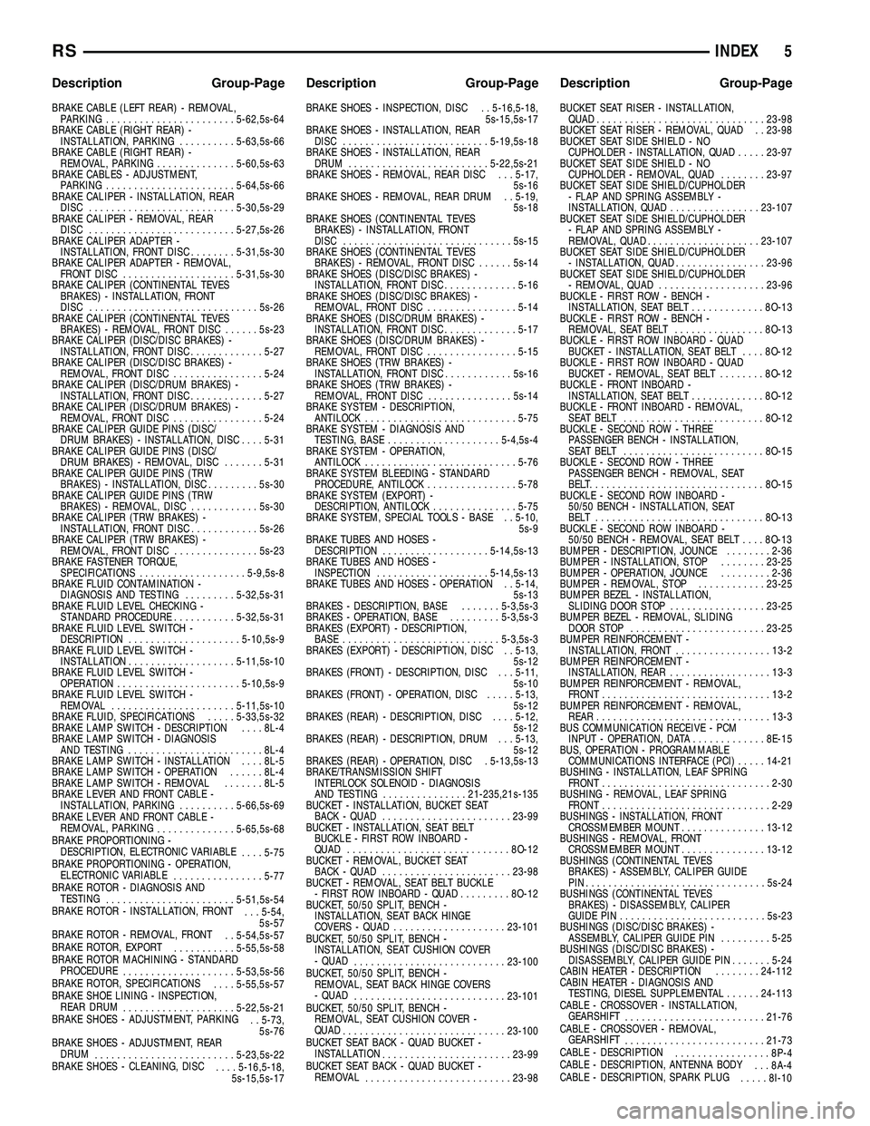
BRAKE CABLE (LEFT REAR) - REMOVAL,
PARKING.......................5-62,5s-64
BRAKE CABLE (RIGHT REAR) -
INSTALLATION, PARKING..........5-63,5s-66
BRAKE CABLE (RIGHT REAR) -
REMOVAL, PARKING..............5-60,5s-63
BRAKE CABLES - ADJUSTMENT,
PARKING.......................5-64,5s-66
BRAKE CALIPER - INSTALLATION, REAR
DISC..........................5-30,5s-29
BRAKE CALIPER - REMOVAL, REAR
DISC..........................5-27,5s-26
BRAKE CALIPER ADAPTER -
INSTALLATION, FRONT DISC........5-31,5s-30
BRAKE CALIPER ADAPTER - REMOVAL,
FRONT DISC....................5-31,5s-30
BRAKE CALIPER (CONTINENTAL TEVES
BRAKES) - INSTALLATION, FRONT
DISC..............................5s-26
BRAKE CALIPER (CONTINENTAL TEVES
BRAKES) - REMOVAL, FRONT DISC......5s-23
BRAKE CALIPER (DISC/DISC BRAKES) -
INSTALLATION, FRONT DISC.............5-27
BRAKE CALIPER (DISC/DISC BRAKES) -
REMOVAL, FRONT DISC................5-24
BRAKE CALIPER (DISC/DRUM BRAKES) -
INSTALLATION, FRONT DISC.............5-27
BRAKE CALIPER (DISC/DRUM BRAKES) -
REMOVAL, FRONT DISC................5-24
BRAKE CALIPER GUIDE PINS (DISC/
DRUM BRAKES) - INSTALLATION, DISC....5-31
BRAKE CALIPER GUIDE PINS (DISC/
DRUM BRAKES) - REMOVAL, DISC.......5-31
BRAKE CALIPER GUIDE PINS (TRW
BRAKES) - INSTALLATION, DISC.........5s-30
BRAKE CALIPER GUIDE PINS (TRW
BRAKES) - REMOVAL, DISC............5s-30
BRAKE CALIPER (TRW BRAKES) -
INSTALLATION, FRONT DISC............5s-26
BRAKE CALIPER (TRW BRAKES) -
REMOVAL, FRONT DISC...............5s-23
BRAKE FASTENER TORQUE,
SPECIFICATIONS...................5-9,5s-8
BRAKE FLUID CONTAMINATION -
DIAGNOSIS AND TESTING.........5-32,5s-31
BRAKE FLUID LEVEL CHECKING -
STANDARD PROCEDURE...........5-32,5s-31
BRAKE FLUID LEVEL SWITCH -
DESCRIPTION....................5-10,5s-9
BRAKE FLUID LEVEL SWITCH -
INSTALLATION...................5-11,5s-10
BRAKE FLUID LEVEL SWITCH -
OPERATION......................5-10,5s-9
BRAKE FLUID LEVEL SWITCH -
REMOVAL......................5-11,5s-10
BRAKE FLUID, SPECIFICATIONS.....5-33,5s-32
BRAKE LAMP SWITCH - DESCRIPTION....8L-4
BRAKE LAMP SWITCH - DIAGNOSIS
AND TESTING........................8L-4
BRAKE LAMP SWITCH - INSTALLATION....8L-5
BRAKE LAMP SWITCH - OPERATION......8L-4
BRAKE LAMP SWITCH - REMOVAL.......8L-5
BRAKE LEVER AND FRONT CABLE -
INSTALLATION, PARKING..........5-66,5s-69
BRAKE LEVER AND FRONT CABLE -
REMOVAL, PARKING
..............5-65,5s-68
BRAKE PROPORTIONING -
DESCRIPTION, ELECTRONIC VARIABLE
....5-75
BRAKE PROPORTIONING - OPERATION,
ELECTRONIC VARIABLE
................5-77
BRAKE ROTOR - DIAGNOSIS AND
TESTING
.......................5-51,5s-54
BRAKE ROTOR - INSTALLATION, FRONT
. . . 5-54,
5s-57
BRAKE ROTOR - REMOVAL, FRONT
. . 5-54,5s-57
BRAKE ROTOR, EXPORT
...........5-55,5s-58
BRAKE ROTOR MACHINING - STANDARD
PROCEDURE
....................5-53,5s-56
BRAKE ROTOR, SPECIFICATIONS
....5-55,5s-57
BRAKE SHOE LINING - INSPECTION,
REAR DRUM
....................5-22,5s-21
BRAKE SHOES - ADJUSTMENT, PARKING
. . 5-73,
5s-76
BRAKE SHOES - ADJUSTMENT, REAR
DRUM
.........................5-23,5s-22
BRAKE SHOES - CLEANING, DISC
....5-16,5-18,
5s-15,5s-17BRAKE SHOES - INSPECTION, DISC . . 5-16,5-18,
5s-15,5s-17
BRAKE SHOES - INSTALLATION, REAR
DISC..........................5-19,5s-18
BRAKE SHOES - INSTALLATION, REAR
DRUM.........................5-22,5s-21
BRAKE SHOES - REMOVAL, REAR DISC . . . 5-17,
5s-16
BRAKE SHOES - REMOVAL, REAR DRUM . . 5-19,
5s-18
BRAKE SHOES (CONTINENTAL TEVES
BRAKES) - INSTALLATION, FRONT
DISC..............................5s-15
BRAKE SHOES (CONTINENTAL TEVES
BRAKES) - REMOVAL, FRONT DISC......5s-14
BRAKE SHOES (DISC/DISC BRAKES) -
INSTALLATION, FRONT DISC.............5-16
BRAKE SHOES (DISC/DISC BRAKES) -
REMOVAL, FRONT DISC................5-14
BRAKE SHOES (DISC/DRUM BRAKES) -
INSTALLATION, FRONT DISC.............5-17
BRAKE SHOES (DISC/DRUM BRAKES) -
REMOVAL, FRONT DISC................5-15
BRAKE SHOES (TRW BRAKES) -
INSTALLATION, FRONT DISC............5s-16
BRAKE SHOES (TRW BRAKES) -
REMOVAL, FRONT DISC...............5s-14
BRAKE SYSTEM - DESCRIPTION,
ANTILOCK...........................5-75
BRAKE SYSTEM - DIAGNOSIS AND
TESTING, BASE....................5-4,5s-4
BRAKE SYSTEM - OPERATION,
ANTILOCK...........................5-76
BRAKE SYSTEM BLEEDING - STANDARD
PROCEDURE, ANTILOCK................5-78
BRAKE SYSTEM (EXPORT) -
DESCRIPTION, ANTILOCK...............5-75
BRAKE SYSTEM, SPECIAL TOOLS - BASE . . 5-10,
5s-9
BRAKE TUBES AND HOSES -
DESCRIPTION...................5-14,5s-13
BRAKE TUBES AND HOSES -
INSPECTION....................5-14,5s-13
BRAKE TUBES AND HOSES - OPERATION . . 5-14,
5s-13
BRAKES - DESCRIPTION, BASE.......5-3,5s-3
BRAKES - OPERATION, BASE.........5-3,5s-3
BRAKES (EXPORT) - DESCRIPTION,
BASE............................5-3,5s-3
BRAKES (EXPORT) - DESCRIPTION, DISC . . 5-13,
5s-12
BRAKES (FRONT) - DESCRIPTION, DISC . . . 5-11,
5s-10
BRAKES (FRONT) - OPERATION, DISC.....5-13,
5s-12
BRAKES (REAR) - DESCRIPTION, DISC....5-12,
5s-12
BRAKES (REAR) - DESCRIPTION, DRUM . . . 5-13,
5s-12
BRAKES (REAR) - OPERATION, DISC . 5-13,5s-13
BRAKE/TRANSMISSION SHIFT
INTERLOCK SOLENOID - DIAGNOSIS
AND TESTING...............21-235,21s-135
BUCKET - INSTALLATION, BUCKET SEAT
BACK - QUAD.......................23-99
BUCKET - INSTALLATION, SEAT BELT
BUCKLE - FIRST ROW INBOARD -
QUAD.............................8O-12
BUCKET - REMOVAL, BUCKET SEAT
BACK - QUAD.......................23-98
BUCKET - REMOVAL, SEAT BELT BUCKLE
- FIRST ROW INBOARD - QUAD.........8O-12
BUCKET, 50/50 SPLIT, BENCH -
INSTALLATION, SEAT BACK HINGE
COVERS - QUAD....................23-101
BUCKET, 50/50 SPLIT, BENCH -
INSTALLATION, SEAT CUSHION COVER
- QUAD
...........................23-100
BUCKET, 50/50 SPLIT, BENCH -
REMOVAL, SEAT BACK HINGE COVERS
- QUAD
...........................23-101
BUCKET, 50/50 SPLIT, BENCH -
REMOVAL, SEAT CUSHION COVER -
QUAD
.............................23-100
BUCKET SEAT BACK - QUAD BUCKET -
INSTALLATION
.......................23-99
BUCKET SEAT BACK - QUAD BUCKET -
REMOVAL
..........................23-98BUCKET SEAT RISER - INSTALLATION,
QUAD..............................23-98
BUCKET SEAT RISER - REMOVAL, QUAD . . 23-98
BUCKET SEAT SIDE SHIELD - NO
CUPHOLDER - INSTALLATION, QUAD.....23-97
BUCKET SEAT SIDE SHIELD - NO
CUPHOLDER - REMOVAL, QUAD........23-97
BUCKET SEAT SIDE SHIELD/CUPHOLDER
- FLAP AND SPRING ASSEMBLY -
INSTALLATION, QUAD................23-107
BUCKET SEAT SIDE SHIELD/CUPHOLDER
- FLAP AND SPRING ASSEMBLY -
REMOVAL, QUAD....................23-107
BUCKET SEAT SIDE SHIELD/CUPHOLDER
- INSTALLATION, QUAD................23-96
BUCKET SEAT SIDE SHIELD/CUPHOLDER
- REMOVAL, QUAD...................23-96
BUCKLE - FIRST ROW - BENCH -
INSTALLATION, SEAT BELT.............8O-13
BUCKLE - FIRST ROW - BENCH -
REMOVAL, SEAT BELT................8O-13
BUCKLE - FIRST ROW INBOARD - QUAD
BUCKET - INSTALLATION, SEAT BELT....8O-12
BUCKLE - FIRST ROW INBOARD - QUAD
BUCKET - REMOVAL, SEAT BELT........8O-12
BUCKLE - FRONT INBOARD -
INSTALLATION, SEAT BELT.............8O-12
BUCKLE - FRONT INBOARD - REMOVAL,
SEAT BELT .........................8O-12
BUCKLE - SECOND ROW - THREE
PASSENGER BENCH - INSTALLATION,
SEAT BELT .........................8O-15
BUCKLE - SECOND ROW - THREE
PASSENGER BENCH - REMOVAL, SEAT
BELT................................8O-15
BUCKLE - SECOND ROW INBOARD -
50/50 BENCH - INSTALLATION, SEAT
BELT ..............................8O-13
BUCKLE - SECOND ROW INBOARD -
50/50 BENCH - REMOVAL, SEAT BELT....8O-13
BUMPER - DESCRIPTION, JOUNCE........2-36
BUMPER - INSTALLATION, STOP........23-25
BUMPER - OPERATION, JOUNCE.........2-36
BUMPER - REMOVAL, STOP............23-25
BUMPER BEZEL - INSTALLATION,
SLIDING DOOR STOP.................23-25
BUMPER BEZEL - REMOVAL, SLIDING
DOOR STOP........................23-25
BUMPER REINFORCEMENT -
INSTALLATION, FRONT.................13-2
BUMPER REINFORCEMENT -
INSTALLATION, REAR..................13-3
BUMPER REINFORCEMENT - REMOVAL,
FRONT..............................13-2
BUMPER REINFORCEMENT - REMOVAL,
REAR...............................13-3
BUS COMMUNICATION RECEIVE - PCM
INPUT - OPERATION, DATA.............8E-15
BUS, OPERATION - PROGRAMMABLE
COMMUNICATIONS INTERFACE (PCI).....14-21
BUSHING - INSTALLATION, LEAF SPRING
FRONT..............................2-30
BUSHING - REMOVAL, LEAF SPRING
FRONT..............................2-29
BUSHINGS - INSTALLATION, FRONT
CROSSMEMBER MOUNT...............13-12
BUSHINGS - REMOVAL, FRONT
CROSSMEMBER MOUNT...............13-12
BUSHINGS (CONTINENTAL TEVES
BRAKES) - ASSEMBLY, CALIPER GUIDE
PIN................................5s-24
BUSHINGS (CONTINENTAL TEVES
BRAKES) - DISASSEMBLY, CALIPER
GUIDE PIN..........................5s-23
BUSHINGS (DISC/DISC BRAKES) -
ASSEMBLY, CALIPER GUIDE PIN.........5-25
BUSHINGS (DISC/DISC BRAKES) -
DISASSEMBLY, CALIPER GUIDE PIN.......5-24
CABIN HEATER - DESCRIPTION........24-112
CABIN HEATER - DIAGNOSIS AND
TESTING, DIESEL SUPPLEMENTAL......24-113
CABLE - CROSSOVER - INSTALLATION,
GEARSHIFT
.........................21-76
CABLE - CROSSOVER - REMOVAL,
GEARSHIFT
.........................21-73
CABLE - DESCRIPTION
.................8P-4
CABLE - DESCRIPTION, ANTENNA BODY
. . . 8A-4
CABLE - DESCRIPTION, SPARK PLUG
.....8I-10
RSINDEX5
Description Group-Page Description Group-Page Description Group-Page
Page 2556 of 2585
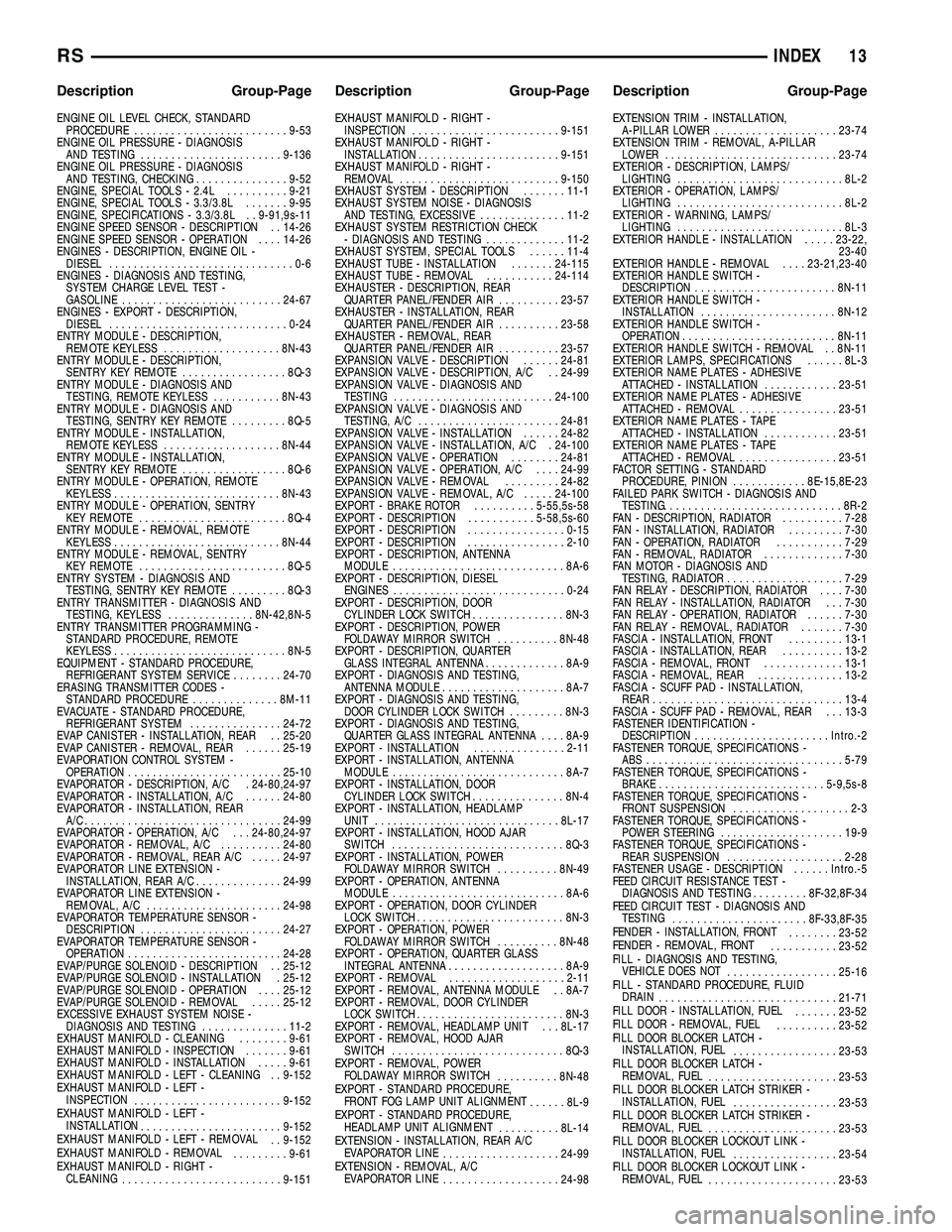
ENGINE OIL LEVEL CHECK, STANDARD
PROCEDURE.........................9-53
ENGINE OIL PRESSURE - DIAGNOSIS
AND TESTING.......................9-136
ENGINE OIL PRESSURE - DIAGNOSIS
AND TESTING, CHECKING...............9-52
ENGINE, SPECIAL TOOLS - 2.4L..........9-21
ENGINE, SPECIAL TOOLS - 3.3/3.8L.......9-95
ENGINE, SPECIFICATIONS - 3.3/3.8L . . 9-91,9s-11
ENGINE SPEED SENSOR - DESCRIPTION . . 14-26
ENGINE SPEED SENSOR - OPERATION....14-26
ENGINES - DESCRIPTION, ENGINE OIL -
DIESEL..............................0-6
ENGINES - DIAGNOSIS AND TESTING,
SYSTEM CHARGE LEVEL TEST -
GASOLINE..........................24-67
ENGINES - EXPORT - DESCRIPTION,
DIESEL.............................0-24
ENTRY MODULE - DESCRIPTION,
REMOTE KEYLESS...................8N-43
ENTRY MODULE - DESCRIPTION,
SENTRY KEY REMOTE.................8Q-3
ENTRY MODULE - DIAGNOSIS AND
TESTING, REMOTE KEYLESS...........8N-43
ENTRY MODULE - DIAGNOSIS AND
TESTING, SENTRY KEY REMOTE.........8Q-5
ENTRY MODULE - INSTALLATION,
REMOTE KEYLESS...................8N-44
ENTRY MODULE - INSTALLATION,
SENTRY KEY REMOTE.................8Q-6
ENTRY MODULE - OPERATION, REMOTE
KEYLESS...........................8N-43
ENTRY MODULE - OPERATION, SENTRY
KEY REMOTE........................8Q-4
ENTRY MODULE - REMOVAL, REMOTE
KEYLESS...........................8N-44
ENTRY MODULE - REMOVAL, SENTRY
KEY REMOTE........................8Q-5
ENTRY SYSTEM - DIAGNOSIS AND
TESTING, SENTRY KEY REMOTE.........8Q-3
ENTRY TRANSMITTER - DIAGNOSIS AND
TESTING, KEYLESS..............8N-42,8N-5
ENTRY TRANSMITTER PROGRAMMING -
STANDARD PROCEDURE, REMOTE
KEYLESS............................8N-5
EQUIPMENT - STANDARD PROCEDURE,
REFRIGERANT SYSTEM SERVICE........24-70
ERASING TRANSMITTER CODES -
STANDARD PROCEDURE..............8M-11
EVACUATE - STANDARD PROCEDURE,
REFRIGERANT SYSTEM...............24-72
EVAP CANISTER - INSTALLATION, REAR . . 25-20
EVAP CANISTER - REMOVAL, REAR......25-19
EVAPORATION CONTROL SYSTEM -
OPERATION.........................25-10
EVAPORATOR - DESCRIPTION, A/C . 24-80,24-97
EVAPORATOR - INSTALLATION, A/C......24-80
EVAPORATOR - INSTALLATION, REAR
A/C................................24-99
EVAPORATOR - OPERATION, A/C . . . 24-80,24-97
EVAPORATOR - REMOVAL, A/C..........24-80
EVAPORATOR - REMOVAL, REAR A/C.....24-97
EVAPORATOR LINE EXTENSION -
INSTALLATION, REAR A/C..............24-99
EVAPORATOR LINE EXTENSION -
REMOVAL, A/C......................24-98
EVAPORATOR TEMPERATURE SENSOR -
DESCRIPTION.......................24-27
EVAPORATOR TEMPERATURE SENSOR -
OPERATION.........................24-28
EVAP/PURGE SOLENOID - DESCRIPTION . . 25-12
EVAP/PURGE SOLENOID - INSTALLATION . 25-12
EVAP/PURGE SOLENOID - OPERATION....25-12
EVAP/PURGE SOLENOID - REMOVAL.....25-12
EXCESSIVE EXHAUST SYSTEM NOISE -
DIAGNOSIS AND TESTING..............11-2
EXHAUST MANIFOLD - CLEANING........9-61
EXHAUST MANIFOLD - INSPECTION.......9-61
EXHAUST MANIFOLD - INSTALLATION.....9-61
EXHAUST MANIFOLD - LEFT - CLEANING . . 9-152
EXHAUST MANIFOLD - LEFT -
INSPECTION
........................9-152
EXHAUST MANIFOLD - LEFT -
INSTALLATION
.......................9-152
EXHAUST MANIFOLD - LEFT - REMOVAL
. . 9-152
EXHAUST MANIFOLD - REMOVAL
.........9-61
EXHAUST MANIFOLD - RIGHT -
CLEANING
..........................9-151EXHAUST MANIFOLD - RIGHT -
INSPECTION........................9-151
EXHAUST MANIFOLD - RIGHT -
INSTALLATION.......................9-151
EXHAUST MANIFOLD - RIGHT -
REMOVAL..........................9-150
EXHAUST SYSTEM - DESCRIPTION.......11-1
EXHAUST SYSTEM NOISE - DIAGNOSIS
AND TESTING, EXCESSIVE..............11-2
EXHAUST SYSTEM RESTRICTION CHECK
- DIAGNOSIS AND TESTING.............11-2
EXHAUST SYSTEM, SPECIAL TOOLS......11-4
EXHAUST TUBE - INSTALLATION.......24-115
EXHAUST TUBE - REMOVAL...........24-114
EXHAUSTER - DESCRIPTION, REAR
QUARTER PANEL/FENDER AIR..........23-57
EXHAUSTER - INSTALLATION, REAR
QUARTER PANEL/FENDER AIR..........23-58
EXHAUSTER - REMOVAL, REAR
QUARTER PANEL/FENDER AIR..........23-57
EXPANSION VALVE - DESCRIPTION......24-81
EXPANSION VALVE - DESCRIPTION, A/C . . 24-99
EXPANSION VALVE - DIAGNOSIS AND
TESTING..........................24-100
EXPANSION VALVE - DIAGNOSIS AND
TESTING, A/C.......................24-81
EXPANSION VALVE - INSTALLATION......24-82
EXPANSION VALVE - INSTALLATION, A/C . 24-100
EXPANSION VALVE - OPERATION........24-81
EXPANSION VALVE - OPERATION, A/C....24-99
EXPANSION VALVE - REMOVAL.........24-82
EXPANSION VALVE - REMOVAL, A/C.....24-100
EXPORT - BRAKE ROTOR..........5-55,5s-58
EXPORT - DESCRIPTION...........5-58,5s-60
EXPORT - DESCRIPTION................0-15
EXPORT - DESCRIPTION................2-10
EXPORT - DESCRIPTION, ANTENNA
MODULE............................8A-6
EXPORT - DESCRIPTION, DIESEL
ENGINES............................0-24
EXPORT - DESCRIPTION, DOOR
CYLINDER LOCK SWITCH...............8N-3
EXPORT - DESCRIPTION, POWER
FOLDAWAY MIRROR SWITCH..........8N-48
EXPORT - DESCRIPTION, QUARTER
GLASS INTEGRAL ANTENNA.............8A-9
EXPORT - DIAGNOSIS AND TESTING,
ANTENNA MODULE....................8A-7
EXPORT - DIAGNOSIS AND TESTING,
DOOR CYLINDER LOCK SWITCH.........8N-3
EXPORT - DIAGNOSIS AND TESTING,
QUARTER GLASS INTEGRAL ANTENNA....8A-9
EXPORT - INSTALLATION...............2-11
EXPORT - INSTALLATION, ANTENNA
MODULE............................8A-7
EXPORT - INSTALLATION, DOOR
CYLINDER LOCK SWITCH...............8N-4
EXPORT - INSTALLATION, HEADLAMP
UNIT..............................8L-17
EXPORT - INSTALLATION, HOOD AJAR
SWITCH............................8Q-3
EXPORT - INSTALLATION, POWER
FOLDAWAY MIRROR SWITCH..........8N-49
EXPORT - OPERATION, ANTENNA
MODULE............................8A-6
EXPORT - OPERATION, DOOR CYLINDER
LOCK SWITCH........................8N-3
EXPORT - OPERATION, POWER
FOLDAWAY MIRROR SWITCH..........8N-48
EXPORT - OPERATION, QUARTER GLASS
INTEGRAL ANTENNA...................8A-9
EXPORT - REMOVAL...................2-11
EXPORT - REMOVAL, ANTENNA MODULE . . 8A-7
EXPORT - REMOVAL, DOOR CYLINDER
LOCK SWITCH........................8N-3
EXPORT - REMOVAL, HEADLAMP UNIT . . . 8L-17
EXPORT - REMOVAL, HOOD AJAR
SWITCH............................8Q-3
EXPORT - REMOVAL, POWER
FOLDAWAY MIRROR SWITCH
..........8N-48
EXPORT - STANDARD PROCEDURE,
FRONT FOG LAMP UNIT ALIGNMENT
......8L-9
EXPORT - STANDARD PROCEDURE,
HEADLAMP UNIT ALIGNMENT
..........8L-14
EXTENSION - INSTALLATION, REAR A/C
EVAPORATOR LINE
...................24-99
EXTENSION - REMOVAL, A/C
EVAPORATOR LINE
...................24-98EXTENSION TRIM - INSTALLATION,
A-PILLAR LOWER....................23-74
EXTENSION TRIM - REMOVAL, A-PILLAR
LOWER............................23-74
EXTERIOR - DESCRIPTION, LAMPS/
LIGHTING...........................8L-2
EXTERIOR - OPERATION, LAMPS/
LIGHTING...........................8L-2
EXTERIOR - WARNING, LAMPS/
LIGHTING...........................8L-3
EXTERIOR HANDLE - INSTALLATION.....23-22,
23-40
EXTERIOR HANDLE - REMOVAL....23-21,23-40
EXTERIOR HANDLE SWITCH -
DESCRIPTION.......................8N-11
EXTERIOR HANDLE SWITCH -
INSTALLATION......................8N-12
EXTERIOR HANDLE SWITCH -
OPERATION.........................8N-11
EXTERIOR HANDLE SWITCH - REMOVAL . . 8N-11
EXTERIOR LAMPS, SPECIFICATIONS......8L-3
EXTERIOR NAME PLATES - ADHESIVE
ATTACHED - INSTALLATION............23-51
EXTERIOR NAME PLATES - ADHESIVE
ATTACHED - REMOVAL................23-51
EXTERIOR NAME PLATES - TAPE
ATTACHED - INSTALLATION............23-51
EXTERIOR NAME PLATES - TAPE
ATTACHED - REMOVAL................23-51
FACTOR SETTING - STANDARD
PROCEDURE, PINION............8E-15,8E-23
FAILED PARK SWITCH - DIAGNOSIS AND
TESTING..............................8R-2
FAN - DESCRIPTION, RADIATOR..........7-28
FAN - INSTALLATION, RADIATOR.........7-30
FAN - OPERATION, RADIATOR...........7-29
FAN - REMOVAL, RADIATOR.............7-30
FAN MOTOR - DIAGNOSIS AND
TESTING, RADIATOR...................7-29
FAN RELAY - DESCRIPTION, RADIATOR....7-30
FAN RELAY - INSTALLATION, RADIATOR . . . 7-30
FAN RELAY - OPERATION, RADIATOR......7-30
FAN RELAY - REMOVAL, RADIATOR.......7-30
FASCIA - INSTALLATION, FRONT.........13-1
FASCIA - INSTALLATION, REAR..........13-2
FASCIA - REMOVAL, FRONT.............13-1
FASCIA - REMOVAL, REAR..............13-2
FASCIA - SCUFF PAD - INSTALLATION,
REAR...............................13-4
FASCIA - SCUFF PAD - REMOVAL, REAR . . . 13-3
FASTENER IDENTIFICATION -
DESCRIPTION......................Intro.-2
FASTENER TORQUE, SPECIFICATIONS -
ABS ................................5-79
FASTENER TORQUE, SPECIFICATIONS -
BRAKE...........................5-9,5s-8
FASTENER TORQUE, SPECIFICATIONS -
FRONT SUSPENSION...................2-3
FASTENER TORQUE, SPECIFICATIONS -
POWER STEERING....................19-9
FASTENER TORQUE, SPECIFICATIONS -
REAR SUSPENSION...................2-28
FASTENER USAGE - DESCRIPTION......Intro.-5
FEED CIRCUIT RESISTANCE TEST -
DIAGNOSIS AND TESTING.........8F-32,8F-34
FEED CIRCUIT TEST - DIAGNOSIS AND
TESTING
......................8F-33,8F-35
FENDER - INSTALLATION, FRONT
........23-52
FENDER - REMOVAL, FRONT
...........23-52
FILL - DIAGNOSIS AND TESTING,
VEHICLE DOES NOT
..................25-16
FILL - STANDARD PROCEDURE, FLUID
DRAIN
.............................21-71
FILL DOOR - INSTALLATION, FUEL
.......23-52
FILL DOOR - REMOVAL, FUEL
..........23-52
FILL DOOR BLOCKER LATCH -
INSTALLATION, FUEL
.................23-53
FILL DOOR BLOCKER LATCH -
REMOVAL, FUEL
.....................23-53
FILL DOOR BLOCKER LATCH STRIKER -
INSTALLATION, FUEL
.................23-53
FILL DOOR BLOCKER LATCH STRIKER -
REMOVAL, FUEL
.....................23-53
FILL DOOR BLOCKER LOCKOUT LINK -
INSTALLATION, FUEL
.................23-54
FILL DOOR BLOCKER LOCKOUT LINK -
REMOVAL, FUEL
.....................23-53
RSINDEX13
Description Group-Page Description Group-Page Description Group-Page