Page 68 of 273

NOTE:The Traction Control System is enabled each
time the ignition switch is turned On. This will occur
even if you used the switch to turn the system off before
powering down or turning the ignition to Lock.
ELECTRONIC SPEED CONTROLÐ IF EQUIPPED
When engaged, this device will control the throttle op-
eration to maintain a constant vehicle speed between 30
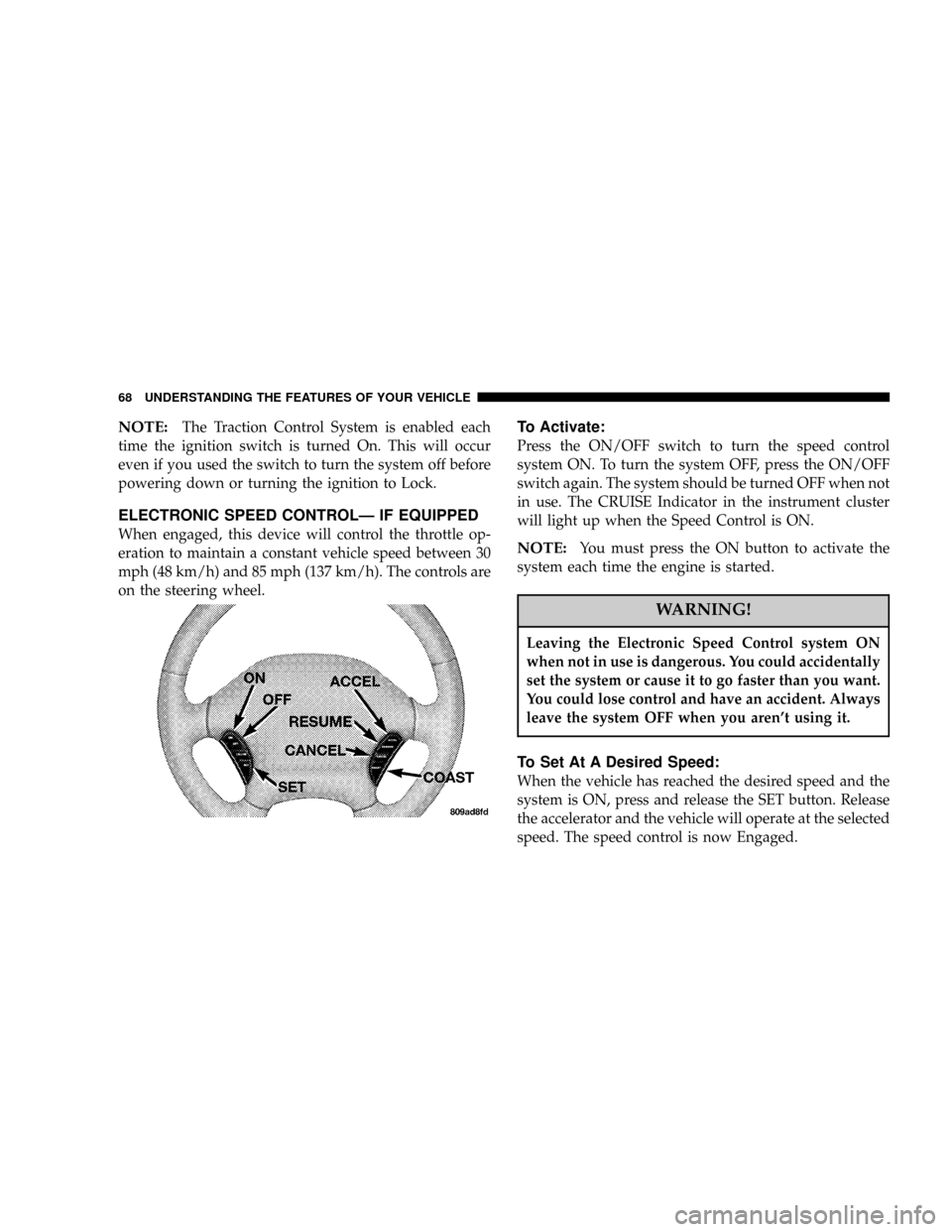
mph (48 km/h) and 85 mph (137 km/h). The controls are
on the steering wheel.
To Activate:
Press the ON/OFF switch to turn the speed control
system ON. To turn the system OFF, press the ON/OFF
switch again. The system should be turned OFF when not
in use. The CRUISE Indicator in the instrument cluster
will light up when the Speed Control is ON.
NOTE:You must press the ON button to activate the
system each time the engine is started.
WARNING!
Leaving the Electronic Speed Control system ON
when not in use is dangerous. You could accidentally
set the system or cause it to go faster than you want.
You could lose control and have an accident. Always
leave the system OFF when you aren't using it.
To Set At A Desired Speed:
When the vehicle has reached the desired speed and the
system is ON, press and release the SET button. Release
the accelerator and the vehicle will operate at the selected
speed. The speed control is now Engaged.
68 UNDERSTANDING THE FEATURES OF YOUR VEHICLE
Page 87 of 273

5. Tachometer
The red area of the scale shows the maximum permissible
engine revolutions-per-minute (rpm x 1000) for each gear
range. Before reaching the red area (over 6,500 rpm), ease
up on the accelerator to prevent engine over speed.
6. Turn Signal Indicators
The arrows will flash in unison with the exterior turn
signal, when using the turn signal lever.
7. High Beam Indicator
This light shows that the headlights are on high
beam. Pull the turn signal lever toward the
steering wheel to switch the headlights from high or
low beam.
8. Speedometer
Shows the vehicle speed in miles-per-hour and
kilometers-per-hour.
9. Charging System Light
This light shows the status of the electrical
charging system. The light should come on
briefly when the ignition is first turned on and remain
on briefly as a bulb check. If the light stays on orcomes on while driving, turn off some of the vehicle's
electrical devices, such as the Fog Lights or Rear
Defroster. If the Charging System Light remains on, it
means that the vehicle is experiencing a problem with
the charging system. Obtain SERVICE IMMEDI-
ATELY. See your local authorized dealer.
10. Malfunction Indicator Light
This light is part of an onboard diagnostic
system called OBD that monitors engine and
automatic transmission control systems. The
light will illuminate as long as the key is in the ON
position, prior to engine start up. Approximately 15
seconds later the MIL may blink for 10 seconds then
resume to full illumination. (See ªEMISSIONS IN-
SPECTION AND MAINTENANCE PROGRAMSº in
the ªMAINTAINING YOUR VEHICLEº section of
your Owner Manual for more details). If the bulb does
not come on when turning the key from OFF to ON,
have the condition checked promptly.
Certain conditions such as a loose or missing gas cap or
poor fuel quality may illuminate the light after engine
start. The vehicle should be serviced if the light stays on
UNDERSTANDING YOUR INSTRUMENT PANEL 87
4
Page 118 of 273

REMOTE SOUND SYSTEM CONTROLS Ð IF
EQUIPPED
The remote sound system controls are located on the rear
surface of the steering wheel. Reach behind the wheel to
access the switches.
The right hand control is a rocker type switch with a
push-button in the center and controls the volume and
mode of the sound system. Pressing the top of the rocker
switch will increase the volume and pressing the bottom
of the rocker switch will decrease the volume.Pressing the center button will make the radio switch
between the various modes available (AM/FM/TAPE/
CD, Etc.).
The left hand control is a rocker type switch with a
push-button in the center. The function of the left hand
control is different depending on which mode you are in.
The following describes the left hand control operation in
each mode.
Radio Operation
Pressing the top of the switch will ªSeekº up for the next
listenable station and pressing the bottom of the switch
will ªSeekº down for the next listenable station.
The button located in the center of the left hand control
will tune to the next preset station that you have pro-
grammed in the radio preset push-button.
Tape Player
Pressing the top of the switch once will go to the next
selection on the cassette. Pressing the bottom of the
switch once will go to the beginning of the current
selection or to the beginning of the previous selection if it
is within the first 5 seconds of the current selection.
118 UNDERSTANDING YOUR INSTRUMENT PANEL
Page 157 of 273

WARNING!
²Do not use a tire, wheel size or rating other than
that specified for your vehicle. Some combina-
tions of unapproved tires and wheels may change
suspension dimensions and performance charac-
teristics, resulting in changes to steering, han-
dling, and braking of your vehicle. This can cause
unpredictable handling and stress to steering and
suspension components. You could lose control
and have an accident resulting in serious injury or
death. Use only the tire and wheel sizes with load
ratings approved for your vehicle.
²Never use a tire with a smaller load index or
capacity, other than what was originally equipped
on your vehicle. Using a tire with a smaller load
index could result in tire overloading and failure.
You could lose control and have an accident.
²Failure to equip your vehicle with tires having
adequate speed capability can result in sudden
tire failure and loss of vehicle control.
CAUTION!
Replacing original tires with tires of a different size
may result in false speedometer and odometer read-
ings.
Alignment And Balance
Poor suspension alignment may result in:
²Fast tire wear.
²Uneven tire wear, such as feathering and one-sided
wear.
²Vehicle pull to right or left.
Tires may also cause the vehicle to pull to the left or right.
Alignment will not correct this condition. See your dealer
for proper diagnosis.
Improper alignment will not cause vehicle vibration.
Vibration may be a result of tire and wheel out-of-
balance. Proper balancing will reduce vibration and
avoid tire cupping and spotty wear.
STARTING AND OPERATING 157
5
Page 172 of 273

HAZARD WARNING FLASHER
The flasher switch is on top of the steering column,
just behind the steering wheel. Depress the switch
and both cluster indicators and all front and rear direc-
tional signals will flash. Depress the switch again to turn
Hazard Warning Flashers off.
Do not use this emergency warning system when the
vehicle is in motion. Use it when your vehicle is disabled
and is creating a safety hazard for other motorists.If it is necessary to leave the vehicle to go for service, the
flasher system will continue to operate with the ignition
key removed and the vehicle locked.
NOTE:With extended use, the flasher may wear down
your battery.
IF YOUR ENGINE OVERHEATS
In any of the following situations, you can reduce the
potential for overheating by taking the appropriate ac-
tion.
²On the highways Ð Slow down.
²In city traffic Ð While stopped, put transaxle in
neutral, but do not increase engine idle speed.
NOTE:There are steps that you can take to slow down
an impending overheat condition. If your air conditioner
is on, turn it off. The air conditioning system adds heat to
the engine cooling system and turning off the A/C
removes this heat. You can also turn the Temperature
control to maximum heat, the Mode control to floor, and
172 WHAT TO DO IN EMERGENCIES
Page 183 of 273

FREEING A STUCK VEHICLE
If your vehicle is equipped with Traction Control, turn
the system off before attempting to ªrockº the vehicle.
If your vehicle becomes stuck in mud, sand or snow, it
can often be moved by a rocking motion. Turn your
steering wheel right and left to clear the area around the
front wheels. Then shift back and forth between Reverse
and First gear. Usually the least accelerator pedal pres-
sure to maintain the rocking motion without spinning the
wheels is most effective.
CAUTION!
Racing the engine or spinning the wheels too fast
may lead to transaxle overheating and failure. It can
also damage the tires. Do not spin the wheels above
30 mph (48 km/h).
TOWING A DISABLED VEHICLE
Flat bed towing is the preferred towing method. If a flat
bed towing vehicle is not available, a wheel lift towing
vehicle may be used.
Rear towing is not recommended with the front wheels
on the ground, as transaxle damage can result. If rear
towing is the only alternative, a front end dolly must be
used.
CAUTION!
Do not use sling type towing equipment. Damage to
the fascia and air dam may result.
WHAT TO DO IN EMERGENCIES 183
6
Page 184 of 273

TOWING THIS VEHICLE BEHIND ANOTHER
VEHICLE (Flat towing with all four wheels on the
ground)
Automatic Transaxle
Your vehicle may be towed under the following condi-
tions: The gear selector must be in NEUTRAL, the
distance to be towed must not exceed 15 miles (25 km),
and the towing speed must not exceed 25 mph (40
km/h). If the transaxle is not operative, or if the vehicle
is to be towed more than 15 miles (25 km), the vehicle
must be towed with the front wheels off the ground.
Manual Transaxle
If your vehicle is equipped with a manual transaxle, it
may be towed at any legal highway speed, for any
distance, if the transaxle is in neutral.
All Transaxles
CAUTION!
If the vehicle being towed requires steering, the
ignition switch must be in the OFF position, not in
the LOCK or ACCESSORY positions.
If it is necessary to use the accessories while being towed
(wipers, defrosters, etc.), the key must be in the ON
position, not the ACCESSORY position. Make certain the
transaxle remains in NEUTRAL.
184 WHAT TO DO IN EMERGENCIES
Page 198 of 273

²Do not idle the engine with any spark plug wires
disconnected for prolonged period.
Engine Timing Belt
Replace the engine timing belt (2.4L Only) at the intervals
described in the appropriate maintenance schedule.
Crankcase Emission Control System
Proper operation of this system depends on freedom
from sticking or plugging due to deposits. As vehicle
mileage builds up, the Positive Crankshaft Ventilation
(PCV) valve and passages may accumulate deposits. If a
valve is not working properly, replace it with a new
valve. DO NOT ATTEMPT TO CLEAN THE OLD PCV
VALVE!
Check ventilation hose for indication of damage or
plugging deposits. Replace if necessary.
Maintenance-Free Battery
The top of the MAINTENANCE-FREE battery is perma-
nently sealed. You will never have to add water, nor is
periodic maintenance required.
NOTE:The battery is stored in a compartment behind
the left front fender and is accessible without removing
the tire and wheel. Remote battery terminals are located
in the engine compartment for jump starting.
To access the battery, turn the steering wheel fully to the
right and remove the inner fender shield.
198 MAINTAINING YOUR VEHICLE