Page 25 of 52
25
Tailgate
The tailgate on the X5 is two sections that
open up and down. The upper section has a
fixed bonded rear glass that incorporates the
rear window wiper and motor assembly. Two
gas strut pistons are used on the upper sec-
tion for opening. An electric actuator is incor-
porated in the upper section with the micro
switch for operation located between the two
license plate lights. The actuator locks into
the lower tailgate section when closed.
A micro-switch positioned in the center console switch
panel is used to open the tail gate from inside the
vehicle.
Operation of the upper tail gate is con-
trolled from the GM which locks the
operation of the gate when the vehicle
speed is over 5 MPH. A dealer installed
class three trailer hitch is available as an
option with a towing capacity of 6000
pounds.
00530015
00530016
Page 26 of 52
26
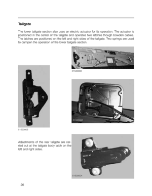
Tailgate
The lower tailgate section also uses an electric actuator for its operation. The actuator is
positioned in the center of the tailgate and operates two latches though bowden cables.
The latches are positioned on the left and right sides of the tailgate. Two springs are used
to dampen the operation of the lower tailgate section.
Adjustments of the rear tailgate are car-
ried out at the tailgate body latch on the
left and right sides.
51530003
51530004
5153000551530006
Page 27 of 52
27
Tailgate (Emergency Opening)
Both sections of the tailgate incorporate emergency release mechanisms for opening the
tailgate in the event of electrical or component failures.
The upper tailgate release is a plastic pull tab positioned on the right side of the inner trim
cover. Pulling the release tab will mechanically release the upper actuator.
The lower tailgate emergency release is accessed by removing the trim cover on the tail-
gate section. With the gate closed, only the top section will be able to be loosened. The
mechanical release is actuated by inserting a small screwdriver into the opening and press-
ing the latch to the left.
Emergency Release
Emergency Release
Page 28 of 52

28
Drivetrain
The transfer case, driveshafts, final drives and half shafts make up the drivetrain assembly.
The transfer case is always mounted in the same position on the X5. This applies to other
markets and future models that will utilize different transmissions for different engine con-
figurations. With these models, the transmission tail shafts will be modified to match up with
the transfer case.
The rear driveshaft is a two piece unit using a center bearing, while the front drive shaft is
a single piece that is splined to the transfer case and bolted to the front differential.
The breather vents for both differentials and the transfer case are mounted higher up on the
chassis to prevent water from entering if the vehicle is driven off road through water. The
front breather passes up into the engine compartment and is mounted under the left side
ignition coil cover. The rear breather passes along the under side of the body and is mount-
ed behind the left side wheel arch cover. The breather vent for the transfer case is mount-
ed up high in the driveshaft tunnel.
26530010.jpg
26530011.jpg
Page 29 of 52
29
Drivetrain-Transfer Case
The transfer case is manufactured by New Process Gear Division of New Venture Gear
Company. It is identified as model NV 125.
It incorporates a planetary gear set and chain to provide the torque split and all wheel drive.
The output torque of the transmission is applied to the planetary carrier of the gear set. The
rear drive shaft is connected to the annulus gear and the front drive shaft is connected to
the sun gear through the chain drive.
As the output shaft of the transmission turns, the planetary carrier rotates, causing the
planetary gears to drive the sun gear and annulus gear.
A torque split of 68% rear/ 32% front is provided through the gearing of the planetary set.
26530003
26530004
Page 30 of 52
30
Drivetrain-Final Drives
The final drives for the front and rear axles are conventional differentials. The DSC system
provides anti-spin/slip control for both the front and rear axles on the X5.
The rear differential is the HAG 188K
(compact) unit with a ratio of 3.64 : 1
The front differential is the VAG 174
unit with a ratio of 3.64 : 1.
26530006
26530007
Page 31 of 52
31
Front Suspension
The front suspension design is taken from the E38/E39 double pivot system. The compo-
nents are larger in size and made from all steel for the expected harder use that the X5 sus-
pension will receive. This includes the sub-frame which is also larger in size and supported
by two hydraulic mounts for vibration absorbion. The front suspension carrier incorporates
an aluminum stiffening plate that is bolted to the carrier. It adds to the front axle kinematics
by reducing flex in the front suspension. It also provides protection for the oil pan and front
end components when off-road and improves the Cd by providing a smooth surface for air
flow under the vehicle.
31530001
Front Axle Technical Data
TRACK: 1576mm
TOE-IN: 18’ +/-10’
CAMBER: -12’ +/- 20’
S.A.I: 12 Degree’s 48 Feet
CASTER: 7 Degree’s 8 Feet
Page 32 of 52
32
Front Suspension Alignment
The front suspension is adjustable for
toe-in and camber. The camber cor-
rection is limited to +/- 12 minutes
through the elongated slots at the top
of the strut towers.
The locating pin at the strut mount is
pressed in place and must be pried
out for removal in order to make any
camber corrections.
32530000
32530001


Both sections of the tailgate incorporate emergency release mechanisms for opening the
tailgate in the event of electrical or component failures.
The upper")


