2004 BMW 325XI child lock
[x] Cancel search: child lockPage 8 of 182
Contents
Notes
About this Owner's Manual4
Additional sources of
information4
Symbols used4
Your individual vehicle5
Status at time of printing5
For your own safety5
Symbol on vehicle parts6
Service and warranty7
Reporting safety defects7
Overview
Cockpit14
Instrument cluster16
Indicator and warning lamps18
Buttons in steering wheel*22
Hazard warning triangle*23
First-aid kit*23
Refueling24
Fuel specifications25
Tire inflation pressure25
Controls and features
Opening and closing:
Keys32
Central locking system32
Opening and closing – via the
remote control33
Opening and closing – via the
door lock36
Opening and closing – from the
inside37
Luggage compartment lid38
Luggage compartment40
Alarm system*41
Electric power windows43
Glass sunroof, electric*44
To adjust:
Safe seating position47
Seats48
Manual seat adjustment48
Power seat adjustment*50
Lumbar support*50
Head restraints51
Safety belts51
Seat and mirror memory*53
Seat heating*54
Steering wheel55
Mirrors55
Passenger safety systems:
Airbags57
Transporting children safely60
Vehicle Memory, Key
Memory64
Page 43 of 182

43
Electric power windowsTo open and close windows
When leaving the vehicle, always
remove the ignition key from the
lock and remember to close the doors
to prevent children from operating the
power windows and injuring them-
selves, etc.<
After the ignition has been switched off:
You can still operate the electric power
windows for up to 15 minutes, as long
as no one opens either of the front
doors.
With the ignition key in position 1 or
higher:
>Press the switch until you feel resis-
tance: the window retracts as long as
you maintain pressure on the switch
>Press the switch briefly past the pres-
sure point: the window moves auto-
matically. Pressing the switch again
stops the opening cycle.
You can close the windows in the same
manner by pulling the switch.
Separate switches are located under
the windows in the rear passenger
area.
For convenience operation via the
remote control or the door lock, refer to
page 34 or 36.Safety featureA contact strip is located on the inside
upper frame of each of the front win-
dows. If pressure is exerted against this
contact strip while a window is being
raised, the system will respond by stop-
ping the window and then retracting it a
small distance.Despite this safety feature, be
extremely careful to ensure that
the closing path of the window is not
obstructed. Some types of objects
might fail to trigger the contact strip in
some situations – very thin objects, for
instance.
You can override this safety feature by
pressing the switch beyond the resis-
tance point and holding it.<
OverviewControlsMaintenanceRepairsDataIndex
Page 44 of 182
44
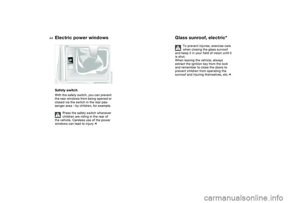
Safety switchWith the safety switch, you can prevent
the rear windows from being opened or
closed via the switch in the rear pas-
senger area – by children, for example.
Press the safety switch whenever
children are riding in the rear of
the vehicle. Careless use of the power
windows can lead to injury.<
Glass sunroof, electric*
To prevent injuries, exercise care
when closing the glass sunroof
and keep it in your field of vision until it
is shut.
When leaving the vehicle, always
extract the ignition key from the lock
and remember to close the doors to
prevent children from operating the
sunroof and injuring themselves, etc.<
Electric power windows
Page 61 of 182

61
Before installing any child-
restraint device or child seat,
please read the following:
Never install a rearward-facing child-
restraint system in the front passenger
seat of this vehicle.
Your vehicle is equipped with an airbag
supplemental restraint system for the
front passenger. Because the backrest
on any rearward-facing child-restraint
system – of the kind designed for
infants under 1 year and 20 lbs/9 kg –
would be within the airbag's deploy-
ment range, you should never mount
such a device in the front passenger
seat, since the impact of the airbag
against the child-restraint's backrest
could lead to serious or fatal injuries.
If it is necessary for a child – not an
infant – to ride in the front seat, certain
precautions should be taken. First,
move the passenger seat as far away
from the dashboard as possible. This
important precaution is intended to
maximize the distance between the air-
bag and the child. Older children
should be tightly secured with a safety
belt after they have outgrown a booster
seat that is appropriate for their age,
height, and weight. Younger children
should be secured in an appropriate
forward-facing child-restraint system
that has first been properly installed
with a safety belt.
Never install a rearward-facing child-
restraint system in the front passenger
seat.
We strongly urge you to carefully read
and comply with the instructions for
installation and use provided by the
child-restraint's manufacturer whenever
you use such a device.
Do not attempt to modify child-restraint
systems. If you do this, the protection
provided by these systems could be
impaired.
Always ensure that all occupants – of all
ages – remain properly and securely
restrained at all times.<
All rear seating positions in your vehicle
meet the recommendations of
SAE J1819, an industry-recommended
practice for securing child-restraint sys-
tems in motor vehicles.
Securing child-restraint systemAll of the rear belt retractors and the
front passenger's safety belt can be
locked for mounting and securing child-
restraint systems.
A label with the appropriate instructions
for this is located in the immediate
vicinity of the buckle latch of each
safety belt.To lock the safety beltExtract the entire length of the belt from
the inertia reel mechanism. Allow the
reel to retract the belt somewhat and
engage the buckle, then tighten the belt
against the child-restraint system. The
retraction mechanism is now locked.
Transporting children safely
OverviewControlsMaintenanceRepairsDataIndex
Page 62 of 182
62
The belt cannot be extracted further.
Always observe the installation instruc-
tions provided by the manufacturer of
the child-restraint system.To unlock the safety beltRelease the safety belt, remove the
child seat and retract the safety belt to
its end position on the belt retractor.
LATCH child-restraint mounting
systemLATCH: Lower Anchors and Tethers for
CHildren
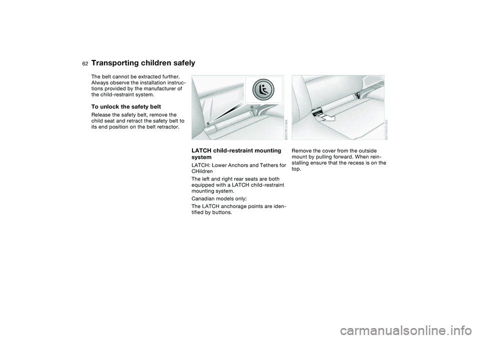
The left and right rear seats are both
equipped with a LATCH child-restraint
mounting system.
Canadian models only:
The LATCH anchorage points are iden-
tified by buttons.
Remove the cover from the outside
mount by pulling forward. When rein-
stalling ensure that the recess is on the
top.
Transporting children safely
Page 63 of 182
63
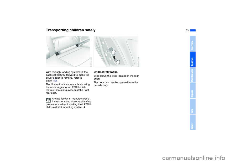
With through-loading system: tilt the
backrest halfway forward to make the
cover easier to remove, refer to
page 112.
The illustration is an example showing
the anchorages for a LATCH child-
restraint mounting system at the right
rear seat.
Always follow all manufacturer's
instructions and observe all safety
precautions when installing the LATCH
child-restraint mounting system.<
Child safety locksSlide down the lever located in the rear
door:
The door can now be opened from the
outside only.
Transporting children safely
OverviewControlsMaintenanceRepairsDataIndex
Page 134 of 182
134
Coolant
Do not add coolant to the cooling
system when the engine is hot. If
you attempt to do so, escaping coolant
can cause burns.
Antifreeze and anti-corrosion agents
are hazardous to health. You should
always store them in closed original
containers and in a location which is
out of reach of children. Antifreeze and
anti-corrosion agents are inflammable.
For this reason, do not spill them on hot
engine parts. They could ignite and
cause serious burns. Comply with the
instructions on the containers.<
Comply with the applicable envi-
ronmental laws regulating the dis-
posal of antifreeze agents with corro-
sion inhibitor.<
Checking the coolant level and
adding coolantCheck the coolant level when the
engine is cold, approx. 687/+206.
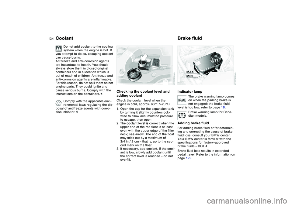
1. Open the cap for the expansion tank
by turning it slightly counterclock-
wise to allow accumulated pressure
to escape, then open
2. The coolant level is correct when the
upper end of the red float is at least
even with the upper edge of the filler
neck; see arrow. The end of the float
may stick out by a maximum of
3/4 in / 2 cm – that is, up to the sec-
ond mark on the float
3. If necessary, add coolant. If the cool-
ant is low, slowly add coolant until
the correct level is reached – do not
overfill.
Brake fluidIndicator lamp
The brake warning lamp comes
on when the parking brake is
not engaged: the brake fluid
level is too low, refer to page 18.
Brake warning lamp for Cana-
dian models.
Adding brake fluidFor adding brake fluid or for determin-
ing and correcting the cause of brake
fluid loss, consult your BMW center.
Your BMW center is familiar with the
specifications for factory-approved
brake fluids – DOT 4.
Brake fluid loss results in extended
pedal travel. Refer to the information on
page 122.
Page 167 of 182
Everything from A to Z
167
Belts, refer to Safety
belts 51
Beverage holders 108, 109
Blower
air conditioning 100
automatic climate
control 104
BMW High Performance
Synthetic Oils 133
BMW Maintenance
System 136
BMW sports seat 49
Bore, refer to Engine
data 160
Bottle holders, see Bever-
age holders 108, 109
Brake fluid 134
indicator lamp 18, 134
level 134
Brake force display 93
Brake hydraulic system 122
Brake lamps
bulb replacement 145
indicator lamp, defective
lamp 82
Brake lights
brake force display 93
Brake pads
brake fluid level
18, 122, 134
breaking in 120
disc brakes 122Brake rotors
brake system 122
breaking in 120
Brake system
brake pads, indicator
lamp 19
Brake wear warning
indicator lamp 19
Brakes
ABS 121
brake fluid 134
breaking in 120
indicator/warning lamp
18, 19
parking brake 67
Break-in procedures 120
Bulb replacement, refer to
Lamps and bulbs 143
Bulb, replacing 143
Buttons in steering wheel 22
C
California Proposition 65
warning 138
Can holders, see Beverage
holders 108, 109
Capacities 163
Car battery 151
Car care, refer to the Caring
for your vehicle brochure
Car keys, refer to Keys 32Car radio, refer to Owner's
Manual for Radio/Onboard
Computer
Car telephone
preparation 110
Car telephone, refer to the
separate Owner's Manual
Car vacuum cleaner, con-
necting 110
Car wash, refer to the Caring
for your vehicle brochure
Carpet care, refer to the
Caring for your vehicle
brochure
Cassette operation, refer to
the Owner's Manual for
Radio/Onboard Computer
CBC Cornering Brake Con-
trol 121
warning lamp 18
CD changer, refer to the
Owner's Manual for
Radio/Onboard Computer
CD operation, refer to the
Owner's Manual for
Radio/Onboard Computer
Cellular phone 110
Center high-mount brake
lamp
bulb replacement 146Central locking system 32
button 37
passenger
compartment 37
Changing a wheel 147
Charge indicator lamp 18
Check Control 82
Check Gas Cap
indicator lamp 19
Child safety locks 63
Child seats 60
Child-restraint systems 60
Chock 148
Cigarette lighter 110
Cigarette lighter socket 110
Cleaning chrome parts, refer
to the Caring for your vehi-
cle brochure
Cleaning light alloy wheels,
refer to the Caring for your
vehicle brochure
Cleaning the vehicle, refer to
the Caring for your vehicle
brochure
Cleaning windshield 78
Clock 83
12-/24-hour mode 83
setting, refer also to the
Owner's Manual for
Radio/Onboard Computer
OverviewControlsMaintenanceRepairsDataIndex