Page 87 of 644
SPEC
2 - 8
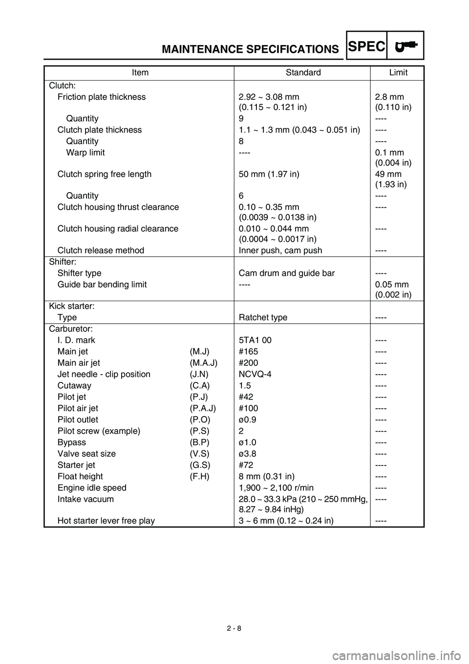
MAINTENANCE SPECIFICATIONS
Clutch:
Friction plate thickness 2.92 ~ 3.08 mm
(0.115 ~ 0.121 in)2.8 mm
(0.110 in)
Quantity 9 ----
Clutch plate thickness 1.1 ~ 1.3 mm (0.043 ~ 0.051 in) ----
Quantity 8 ----
Warp limit ---- 0.1 mm
(0.004 in)
Clutch spring free length 50 mm (1.97 in) 49 mm
(1.93 in)
Quantity 6 ----
Clutch housing thrust clearance 0.10 ~ 0.35 mm
(0.0039 ~ 0.0138 in)----
Clutch housing radial clearance 0.010 ~ 0.044 mm
(0.0004 ~ 0.0017 in)----
Clutch release method Inner push, cam push ----
Shifter:
Shifter type Cam drum and guide bar ----
Guide bar bending limit ---- 0.05 mm
(0.002 in)
Kick starter:
Type Ratchet type ----
Carburetor:
I. D. mark 5TA1 00 ----
Main jet (M.J) #165 ----
Main air jet (M.A.J) #200 ----
Jet needle - clip position (J.N) NCVQ-4 ----
Cutaway (C.A) 1.5 ----
Pilot jet (P.J) #42 ----
Pilot air jet (P.A.J) #100 ----
Pilot outlet (P.O)ø0.9 ----
Pilot screw (example) (P.S) 2 ----
Bypass (B.P)ø1.0 ----
Valve seat size (V.S)ø3.8 ----
Starter jet (G.S) #72 ----
Float height (F.H) 8 mm (0.31 in) ----
Engine idle speed 1,900 ~ 2,100 r/min ----
Intake vacuum28.0 ~ 33.3 kPa (210 ~ 250 mmHg,
8.27 ~ 9.84 inHg)----
Hot starter lever free play 3 ~ 6 mm (0.12 ~ 0.24 in)---- Item Standard Limit
Page 262 of 644
4 - 9
ENGCARBURETOR
CARBURETOR DISASSEMBLY
Extent of removal:1 Carburetor disassembly
Extent of removal Order Part name Q’ty Remarks
CARBURETOR DISASSEMBLY
1Breather hose 4
2Valve lever housing cover 1
3Screw (throttle shaft) 1
4Throttle valve 1
5Needle holder 1
6Jet needle 1
7Cover 1
8Spring 1
9Diaphragm (accelerator pump) 1
0Float chamber 1
APilot screw 1 Refer to “REMOVAL POINTS”.
BFloat pin 1
CFloat 1
DNeedle valve 1
1
Page 264 of 644
4 - 10
ENGCARBURETOR
Extent of removal Order Part name Q’ty Remarks
EMain jet 1
FNeedle jet 1
GSpacer 1
HPilot jet 1
IStarter jet 1
JPush rod 1 Pull the push rod.
KThrottle shaft assembly 1
LPush rod link lever assembly 1
MPilot air jet 1
NCold starter plunger
1
1
Page 268 of 644
4 - 12
ENGCARBURETOR
2. Inspect:
�Main jet 1
�Pilot jet 2
�Needle jet 3
�Starter jet 4
�Pilot air jet 5
Damage → Replace.
Contamination → Clean.
NOTE:
�Use a petroleum based solvent for cleaning.
Blow out all passages and jets with com-
pressed air.
�Never use a wire.
Needle valve
1. Inspect:
�Needle valve 1
�Valve seat 2
Grooved wear a → Replace.
Dust b → Clean.
EC464300
Throttle valve
1. Check:
�Free movement
Stick → Repair or replace.
Insert the throttle valve 1 into the car-
buretor body, and check for free move-
ment.
EC464400
Jet needle
1. Inspect:
�Jet needle 1
Bends/wear → Replace.
�Clip groove
Free play exists/wear → Replace.
�Clip position
Standard clip position:
No.4 Groove
Page 270 of 644

4 - 13
ENGCARBURETOR
EC464511
Float height
1. Measure:
�Float height a
Out of specification → Adjust.
Float height:
8.0 mm (0.31 in)
Measurement and adjustment steps:
�Hold the carburetor in an upside down
position.
NOTE:
�Slowly tilt the carburetor in the opposite
direction, then take the measurement
when the needle valve aligns with the float
arm.
�If the carburetor is level, the weight of the
float will push in the needle valve, result-
ing in an incorrect measurement.
�Measure the distance between the mating
surface of the float chamber and top of the
float using a vernier calipers.
NOTE:
The float arm should be resting on the nee-
dle valve, but not compressing the needle
valve.
�If the float height is not within specifica-
tion, inspect the valve seat and needle
valve.
�If either is worn, replace them both.
�If both are fine, adjust the float height by
bending the float tab b on the float.
�Recheck the float height.
EC464600
Float
1. Inspect:
�Float 1
Damage → Replace.
Page 276 of 644
4 - 16
ENGCARBURETOR
8. Install:
�Throttle shaft assembly 1
�Plain washer (metal) 2
�Plain washer (resin) 3
�Valve lever 4
NOTE:
�Apply the fluorochemical grease on the bear-
ings.
�Fit the projection a on the throttle shaft
assembly into the slot b in the TPS (throttle
position sensor).
�Make sure the stopper c of the spring fits
into the recess in the carburetor.
�Turn the throttle shaft assembly left while
holding down the lever 1 5 and fit the throt-
tle stop screw tip d to the stopper e of the
throttle shaft assembly pulley.
1
23
4
b
a
c
e
d
5
9. Install:
�Push rod 1
NOTE:
While holding down the lever 1 2, insert the
push rod farthest into the carburetor.12
10. Install:
�Starter jet 1
�Pilot jet 2
�Spacer 3
�Needle jet 4
�Main jet 5
Page 278 of 644
4 - 17
ENGCARBURETOR
11. Install:
�Needle valve 1
�Float 2
�Float pin 3
NOTE:
�After installing the needle valve to the float,
install them to the carburetor.
�Check the float for smooth movement.
12. Install:
�Pilot screw 1
�Spring 2
�Washer 3
�O-ring 4
Note the following installation points:
�Turn in the pilot screw until it is lightly
seated.
�Turn out the pilot screw by the number of
turns recorded before removing.
Pilot screw:
2 turns out (example)
13. Install:
�O-ring
�Float chamber 1
�Screw (float chamber) 2
�Cable holder (throttle stop screw cable)
3
�Hose holder (carburetor breather hose)
4
14. Install:
�Diaphragm (accelerator pump) 1
�Spring 2
�O-ring 3
�Cover 4
�Hose holder (drain hose) 5
�Screw (cover) 6
NOTE:
Install the diaphragm (accelerator pump) with
its mark a facing the spring.
421 3
4
Page 280 of 644
4 - 18
ENGCARBURETOR
15. Install:
�Jet needle 1
�Collar 2
�Spring 3
�Needle holder 4
�Throttle valve plate 5
To throttle valve 6.
5
6
1
2
3
4
16. Install:
�Throttle valve assembly 1
�Screw (throttle shaft) 2
NOTE:
Install the valve lever rollers 3 into the slits a
of the throttle valve.
17. Install:
�O-ring 1
�Valve lever housing cover 2
�Bolt (valve lever housing cover) 3
18. Install:
�Carburetor breather hose 1
Refer to “CABLE ROUTING DIAGRAM”
section in the CHAPTER 2.


