Page 298 of 644

4 - 27
ENGCAMSHAFTS
�Fit the timing chain 3 onto both camshaft
sprockets and install the camshafts on the
cylinder head.
NOTE:
The camshafts should be installed onto the
cylinder head so that the exhaust cam
sprocket punch mark c and the intake cam
sprocket punch mark d align with the sur-
face of the cylinder head.
CAUTION:
Do not turn the crankshaft during the
camshaft installation. Damage or
improper valve timing will result.
�Install the clips and camshaft caps 4.
T R..
Bolt (camshaft cap):
10 Nm (1.0 m • kg, 7.2 ft • lb)
NOTE:
�Apply the engine oil on the thread and con-
tact surface of the bolts (camshaft cap) 5.
�Tighten the bolts (camshaft cap) in a criss-
cross pattern.
CAUTION:
The bolts (camshaft cap) must be tight-
ened evenly, or damage to the cylinder
head, camshaft caps, and camshaft will
result.
5
4
E
2. Install:
�Timing chain tensioner
Installation steps:
�While pressing the tensioner rod lightly
with fingers, use a thin screwdriver and
wind the tensioner rod up fully clockwise.
Page 300 of 644
4 - 28
ENG
�With the rod fully wound and the chain
tensioner UP mark a facing upward,
install the gasket 1 and the chain ten-
sioner 2, and tighten the bolt 3 to the
specified torque.
T R..
Bolt (timing chain tensioner):
10 Nm (1.0 m • kg, 7.2 ft • lb)
�Release the screwdriver, check the ten-
sioner rod to come out and tighten the
gasket 4 and the cap bolt 5 to the speci-
fied torque.
T R..
Tensioner cap bolt:
7 Nm (0.7 m • kg, 5.1 ft • lb)
5
4New
3. Turn:
�Crankshaft
Counterclockwise several turns
4. Check:
�Rotor “I” mark
Align with the crankcase stationary
pointer.
�Camshaft match marks
Align with the cylinder head surface.
Out of alignment → Adjust.
CAMSHAFTS
Page 344 of 644
4 - 50
ENGCLUTCH
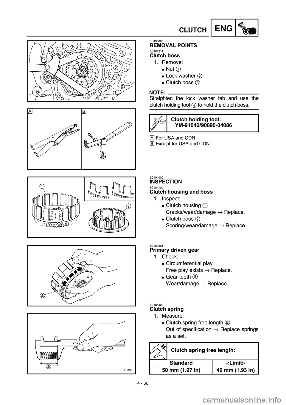
EC493000
REMOVAL POINTS
EC483211
Clutch boss
1. Remove:
�Nut 1
�Lock washer 2
�Clutch boss 3
NOTE:
Straighten the lock washer tab and use the
clutch holding tool 4 to hold the clutch boss.
ÅFor USA and CDN
ıExcept for USA and CDN
Clutch holding tool:
YM-91042/90890-04086
Å
ı
EC494000
INSPECTION
EC484100
Clutch housing and boss
1. Inspect:
�Clutch housing 1
Cracks/wear/damage → Replace.
�Clutch boss 2
Scoring/wear/damage → Replace.
EC484201
Primary driven gear
1. Check:
�Circumferential play
Free play exists → Replace.
�Gear teeth a
Wear/damage → Replace.
EC484400
Clutch spring
1. Measure:
�Clutch spring free length a
Out of specification → Replace springs
as a set.
Clutch spring free length:
Standard
50 mm (1.97 in) 49 mm (1.93 in)
Page 348 of 644
4 - 52
ENGCLUTCH
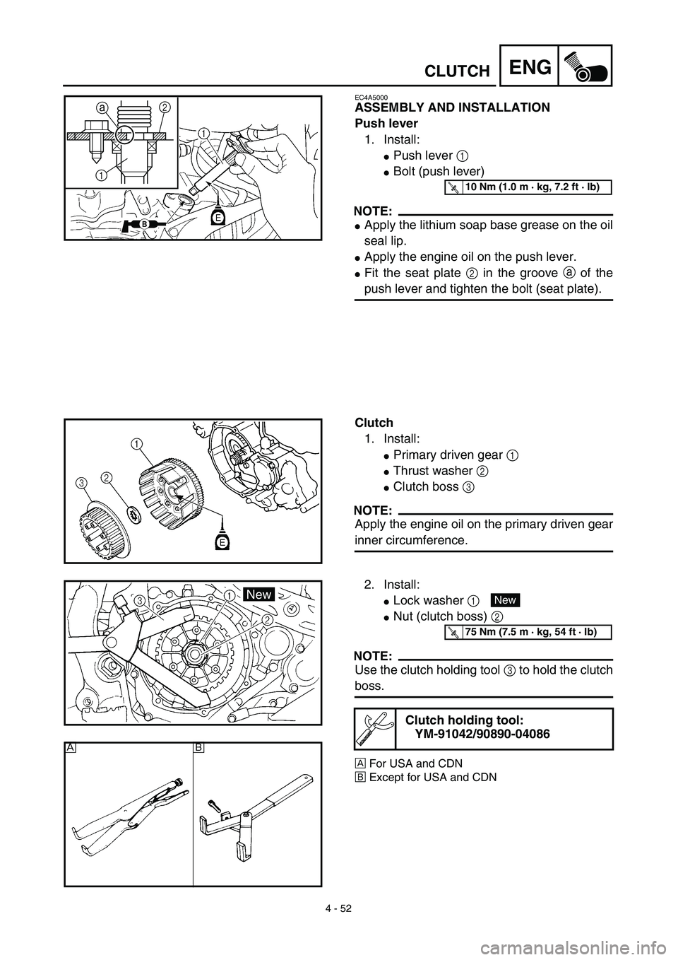
EC4A5000
ASSEMBLY AND INSTALLATION
Push lever
1. Install:
�Push lever 1
�Bolt (push lever)
NOTE:
�Apply the lithium soap base grease on the oil
seal lip.
�Apply the engine oil on the push lever.
�Fit the seat plate 2 in the groove a of the
push lever and tighten the bolt (seat plate).
2
1a
T R..10 Nm (1.0 m · kg, 7.2 ft · lb)
Clutch
1. Install:
�Primary driven gear 1
�Thrust washer 2
�Clutch boss 3
NOTE:
Apply the engine oil on the primary driven gear
inner circumference.
2. Install:
�Lock washer 1
�Nut (clutch boss) 2
NOTE:
Use the clutch holding tool 3 to hold the clutch
boss.
ÅFor USA and CDN
ıExcept for USA and CDN
Clutch holding tool:
YM-91042/90890-04086
New
T R..75 Nm (7.5 m · kg, 54 ft · lb)
Åı
Page 350 of 644
4 - 53
ENGCLUTCH
3. Bend the lock washer 1 tab.
4. Install:
�Friction plate 1
�Clutch plate 2
NOTE:
�Install the clutch plates and friction plates
alternately on the clutch boss, starting with a
friction plate and ending with a friction plate.
�Apply the engine oil on the friction plates and
clutch plates.
2 1
E
5. Install:
�Bearing 1
�Plain washer 2
�Circlip 3
To push rod 1 4.
NOTE:
Apply the engine oil on the bearing and plain
washer.
New
6. Install:
�Push rod 2 1
�Ball 2
�Push rod 1 3
NOTE:
Apply the engine oil on the push rod 1, 2 and
ball.
Page 368 of 644
4 - 62
ENGBALANCER
BALANCER
BALANCER
Extent of removal:1 Balancer drive gear2 Balancer
Extent of removal Order Part name Q’ty Remarks
BALANCER REMOVAL
Preparation for removal Clutch housing Refer to “CLUTCH” section.
Crankcase cover (right)Refer to “OIL FILTER, WATER PUMP AND
CRANKCASE COVER (RIGHT)” section.
Stator Refer to “CDI MAGNETO” section.
1 Nut (primary drive gear) 1
Refer to “REMOVAL POINTS”.
2 Nut (balancer) 1
3 Lock washer 1
4 Primary drive gear 1
5 Balancer drive gear 1
6 Lock washer 1
7 Balancer driven gear 1
8 Balancer 1 Refer to “REMOVAL POINTS”.
2
1
2
Page 370 of 644
4 - 63
ENGBALANCER
REMOVAL POINTS
Balancer drive gear and balancer driven
gear
1. Straighten the lock washer tab.
2. Loosen:
�Nut (primary drive gear) 1
�Nut (balancer) 2
NOTE:
Place an aluminum plate a between the teeth
of the balancer drive gear 3 and driven gear
4.
Balancer
1. Remove:
�Balancer 1
NOTE:
When removing the balancer shaft, align the
center of the balancer shaft weight a along
the line connecting the centers of the crank-
shaft and balancer shaft.
INSPECTION
Primary drive gear, balancer drive gear and
balancer driven gear
1. Inspect:
�Primary drive gear 1
�Balancer drive gear 2
�Balancer driven gear 3
Wear/damage → Replace.
Balancer
1. Inspect:
�Balancer
Cracks/damage → Replace.
Page 371 of 644
 1
�Mutter (Ausgle")
4 - 63
ENG
BALANCIER
AUSGLEICHSWELLE
AUSBAU
Ausgleichswellen-Antriebs- und -Abtriebs-
räder
1. Die Lasche der Sicherungsscheibe um-
biegen.
2. Lockern:
�Mutter (Primärantriebsrad) 1
�Mutter (Ausgleichswelle) 2
HINWEIS:
Ein Stückchen Aluminium a zwischen die
Zähne des Ausgleichswellen-Antriebsrades 3
und Ausgleichswellen-Abtriebrades 4 legen.
Ausgleichswelle
1. Demontieren:
�Ausgleichswelle 1
HINWEIS:
Beim Ausbau der Ausgleichswelle muß sich
das Ausgleichsgewicht mittig a auf der
Fluchtlinie zwischen den Mittelpunkten der
Nockenwellen- und Ausgleichswellen-Enden
befinden.
PRÜFUNG
Primär- und Ausgleichswellen-Antriebs-
und -Abtriebsräder
1. Kontrollieren:
�Primärantriebsrad 1
�Ausgleichswellen-Antriebsrad 2
�Ausgleichswellen-Abtriebsrad 3
Verschleiß/Beschädigung → Erneuern.
Ausgleichswelle
1. Kontrollieren:
�Ausgleichswelle
Rißbildung/Beschädigung → Erneuern. POINTS DE DEPOSE
Pignon menant et pignon mené du balancier
1. Redresser l’ongle de rondelle d’arrêt.
2. Desserrer:
�Ecrou (pignon menant primaire) 1
�Ecrou (balancier) 2
N.B.:
Placer une plaque en aluminium a entre les dents
du pignon menant 3 et le pignon mené 4 du
balancier.
Balancier
1. Déposer:
�Balancier 1
N.B.:
Avant de déposer l’arbre de balancier, aligner le
centre du poids de l’arbre de balancier a avec
l’axe reliant le centre du vilebrequin et le centre de
l’arbre de balancier.
CONTROLE
Pignon menant primaire, pignon menant et
pignon mené du balancier
1. Contrôler:
�Pignon menant primaire 1
�Pignon menant du balancier 2
�Pignon mené du balancier 3
Usure/endommagements → Remplacer.
Balancier
1. Contrôler:
�Balancier
Craquelures/endommagement → Rempla-
cer.