Page 298 of 662
4 - 23
ENGCAMSHAFTS
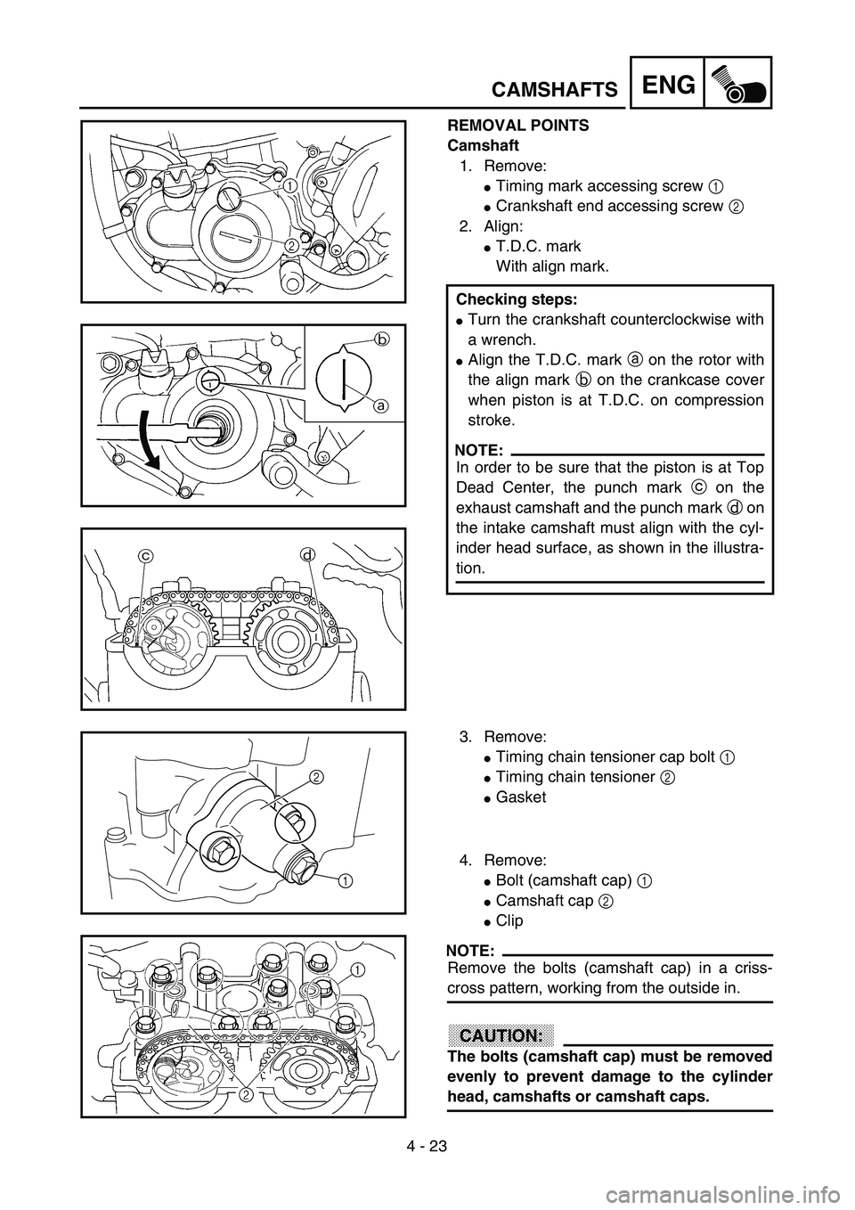
REMOVAL POINTS
Camshaft
1. Remove:
�Timing mark accessing screw 1
�Crankshaft end accessing screw 2
2. Align:
�T.D.C. mark
With align mark.
Checking steps:
�Turn the crankshaft counterclockwise with
a wrench.
�Align the T.D.C. mark a on the rotor with
the align mark b on the crankcase cover
when piston is at T.D.C. on compression
stroke.
NOTE:
In order to be sure that the piston is at Top
Dead Center, the punch mark c on the
exhaust camshaft and the punch mark d on
the intake camshaft must align with the cyl-
inder head surface, as shown in the illustra-
tion.
3. Remove:
�Timing chain tensioner cap bolt 1
�Timing chain tensioner 2
�Gasket
4. Remove:
�Bolt (camshaft cap) 1
�Camshaft cap 2
�Clip
NOTE:
Remove the bolts (camshaft cap) in a criss-
cross pattern, working from the outside in.
CAUTION:
The bolts (camshaft cap) must be removed
evenly to prevent damage to the cylinder
head, camshafts or camshaft caps.
1
2
Page 302 of 662

<Limit>: 0.")
4 - 25
ENGCAMSHAFTS
4. Measure:
�Camshaft-to-cap clearance
Out of specification → Measure cam-
shaft outside diameter.
Camshaft-to-cap clearance:
0.020 ~ 0.054 mm
(0.0008 ~ 0.0021 in)
: 0.08 mm (0.003 in)
Measurement steps:
�Install the camshaft onto the cylinder
head.
�Position a strip of Plastigauge® 1 onto the
camshaft.
�Install the clip, dowel pins and camshaft
caps.
T R..
Bolt (camshaft cap):
10 Nm (1.0 m • kg, 7.2 ft • lb)
NOTE:
�Tighten the bolts (camshaft cap) in a criss-
cross pattern from innermost to outer
caps.
�Do not turn the camshaft when measuring
clearance with the Plastigauge®.
�Remove the camshaft caps and measure
the width of the Plastigauge
® 1.
5. Measure:
�Camshaft outside diameter a
Out of specification → Replace the
camshaft.
Within specification → Replace cam-
shaft case and camshaft caps as a set.
Camshaft sprocket
1. Inspect:
�Camshaft sprocket 1
Wear/damage → Replace the camshaft
assembly and timing chain as a set.
Camshaft outside diameter:
21.967 ~ 21.980 mm
(0.8648 ~ 0.8654 in)
Page 306 of 662

4 - 27
ENGCAMSHAFTS
�Fit the timing chain 3 onto both camshaft
sprockets and install the camshafts on the
cylinder head.
NOTE:
The camshafts should be installed onto the
cylinder head so that the punch mark c on
the exhaust camshaft and the punch mark
d on the intake camshaft must align with
the cylinder head surface, as shown in the
illustration.
CAUTION:
Do not turn the crankshaft during the
camshaft installation. Damage or
improper valve timing will result.
�Install the clips, camshaft caps 4 and
bolts (camshaft cap) 5.
T R..
Bolt (camshaft cap):
10 Nm (1.0 m • kg, 7.2 ft • lb)
NOTE:
�Before removing the clips, cover the cylin-
der head with a clean rag to prevent the
clips from into the cylinder head cavity.
�Apply the engine oil on the thread and con-
tact surface of the bolts (camshaft cap).
�Tighten the bolts (camshaft cap) in a criss-
cross pattern.
CAUTION:
The bolts (camshaft cap) must be tight-
ened evenly, or damage to the cylinder
head, camshaft caps, and camshaft will
result.
2. Install:
�Timing chain tensioner
Installation steps:
�While pressing the tensioner rod lightly
with fingers, use a thin screwdriver and
wind the tensioner rod up fully clockwise.
Page 362 of 662
4 - 55
ENGCLUTCH
7. Install:
�Push rod 2 1
�Ball 2
�Push rod 1 3
NOTE:
Apply the engine oil on the push rod 1, 2 and
ball.
8. Install:
�Pressure plate 1
9. Install:
�Clutch spring 1
�Bolt (clutch spring) 2
NOTE:
Tighten the bolts in stage, using a crisscross
pattern.
T R..8 Nm (0.8 m · kg, 5.8 ft · lb)
10. Install:
�Dowel pin 1
�Gasket (clutch cover) 2
11. Install:
�Clutch cover 1
�Bolt (clutch cover)
NOTE:
Tighten the bolts in stage, using a crisscross
pattern.
T R..10 Nm (1.0 m · kg, 7.2 ft · lb)
Page 374 of 662
4 - 61
ENG
OIL FILTER ELEMENT, WATER PUMP AND RIGHT
CRANKCASE COVER
2. Install:
�Right crankcase cover 1
�Bolt (right crankcase cover) 2
NOTE:
�Apply the engine oil on the impeller shaft
end.
�Mesh the impeller shaft gear 3 with primary
drive gear 4.
�Tighten the bolts in stage, using a crisscross
pattern.
T R..10 Nm (1.0 m · kg, 7.2 ft · lb)
Kickstarter crank
1. Install:
�Kickstarter crank 1
�Washer 2
�Bolt (kickstarter crank) 3
NOTE:
Install the kickstarter crank so that the kick-
starter crank is as vertical as possible with the
distance a between the kickstarter crank and
the frame being 8 mm (0.31 in) or more.
2. Install:
�Oil hose 1
�Bolt (oil hose) 2
T R..33 Nm (3.3 m · kg, 24 ft · lb)
T R..10 Nm (1.0 m · kg, 7.2 ft · lb)
3. Install:
�Copper washer 1
�Oil delivery pipe 2
�Union bolt (M8) 3
�Union bolt (M10) 4
T R..18 Nm (1.8 m · kg, 13 ft · lb)
T R..20 Nm (2.0 m · kg, 14 ft · lb)
Page 414 of 662
4 - 81
ENGCDI MAGNETO
4. Connect:
�CDI magneto lead
Refer to “CABLE ROUTING DIA-
GRAM” section in the CHAPTER 2.
5. Install:
�Dowel pin
�Gasket (left crankcase cover)
�Left crankcase cover 1
�Hose guide (cylinder head breather
hose) 2
�Bolt (left crankcase cover) 3
NOTE:
Tighten the bolts in stage, using a crisscross
pattern.
2
1
3T R..10 Nm (1.0 m · kg, 7.2 ft · lb)
Page 442 of 662
4 - 95
ENGCRANKCASE AND CRANKSHAFT
6. Tighten:
�Hose guide 1
�Clutch cable holder 2
�Bolt (crankcase) 3
NOTE:
Tighten the crankcase tightening bolts in
stage, using a crisscross pattern.
T R..12 Nm (1.2 m · kg, 8.7 ft · lb)
7. Install:
�Oil delivery pipe 2 1
�O-ring 2
�Bolt (oil delivery pipe 2) 3
NOTE:
Apply the lithium soap base grease on the O-
rings.
T R..10 Nm (1.0 m · kg, 7.2 ft · lb)
8. Install:
�Timing chain 1
�Timing chain guide (intake side) 2
�Bolt (timing chain guide) 3
9. Remove:
�Sealant
Forced out on the cylinder mating sur-
face.
10. Apply:
�Engine oil
To the crank pin, bearing and oil deliv-
ery hole.
11. Check:
�Crankshaft and transmission operation.
Unsmooth operation → Repair.
T R..10 Nm (1.0 m · kg, 7.2 ft · lb)
Page 462 of 662
5 - 5
CHAS
FRONT WHEEL AND REAR WHEEL
EC595000
ASSEMBLY AND INSTALLATION
Front wheel
1. Install:
�
Bearing (left)
1
�
Spacer
2
�
Bearing (right)
3
�
Oil seal
4
NOTE:
�
Apply the lithium soap base grease on the
bearing and oil seal lip when installing.
�
Use a socket that matches the outside diam-
eter of the race of the bearing.
�
Left side of bearing shall be installed first.
�
Install the oil seal with its manufacture’s
marks or numbers facing outward.
ACHTUNG:CAUTION:
Do not strike the inner race of the bearing.
Contact should be made only with the outer
race.
2. Install:
�Brake disc 1
�Bolt (brake disc) 2
NOTE:
Tighten the bolts in stage, using a crisscross
pattern.
T R..12 Nm (1.2 m · kg, 8.7 ft · lb)
3. Install:
�Collar 1
NOTE:
�Apply the lithium soap base grease on the oil
seal lip.
�Install the collars with their projections a
facing the wheel.
4. Install:
�Wheel
NOTE:
Install the brake disc 1 between the brake
pads 2 correctly.