Page 336 of 754
4 - 18
ENGCARBURETOR
15. Install:
�Diaphragm (accelerator pump) 1
�Spring 2
�O-ring 3
�Cover 4
�Hose holder (drain hose) 5
�Screw (cover) 6
NOTE:
Install the diaphragm (accelerator pump) with
its mark a facing the spring.
16. Install:
�Jet needle 1
�Collar 2
�Spring 3
�Needle holder 4
�Throttle valve plate 5
To throttle valve 6.
5
6
1
2
3
4
17. Install:
�Throttle valve assembly 1
�Screw (throttle shaft) 2
NOTE:
Install the valve lever rollers 3 into the slits a
of the throttle valve.
18. Install:
�O-ring 1
�Valve lever housing cover 2
�Bolt (valve lever housing cover) 3
19. Install:
�Carburetor breather hose 1
Refer to “CABLE ROUTING DIA-
GRAM” section in the CHAPTER 2.
Page 338 of 754
4 - 19
ENGCARBURETOR
Accelerator pump timing adjustment
Adjustment steps:
NOTE:
In order for the throttle valve height a to
achieve the specified value, tuck under the
throttle valve plate 1 the rod 2 etc. with
the same outer diameter as the specified
value.
Throttle valve height:
3.1 mm (0.122 in)
�Fully turn in the accelerator pump adjust-
ing screw 3.
�Check that the link lever 4 has free play
b by pushing lightly on it.
�Gradually turn out the adjusting screw
while moving the link lever until it has no
more free play.
Carburetor installation
1. Install:
�Carburetor joint 1
NOTE:
Install the projection a on the cylinder head
between the carburetor joint slots b.
T R..3 Nm (0.3 m · kg, 2.2 ft · lb)
2. Install:
�Carburetor 1
NOTE:
Install the projection a between the carburetor
joint slots.
3. Install:
�Hot starter plunger 1
1
T R..2 Nm (0.2 m · kg, 1.4 ft · lb)
Page 340 of 754
4 - 20
ENG
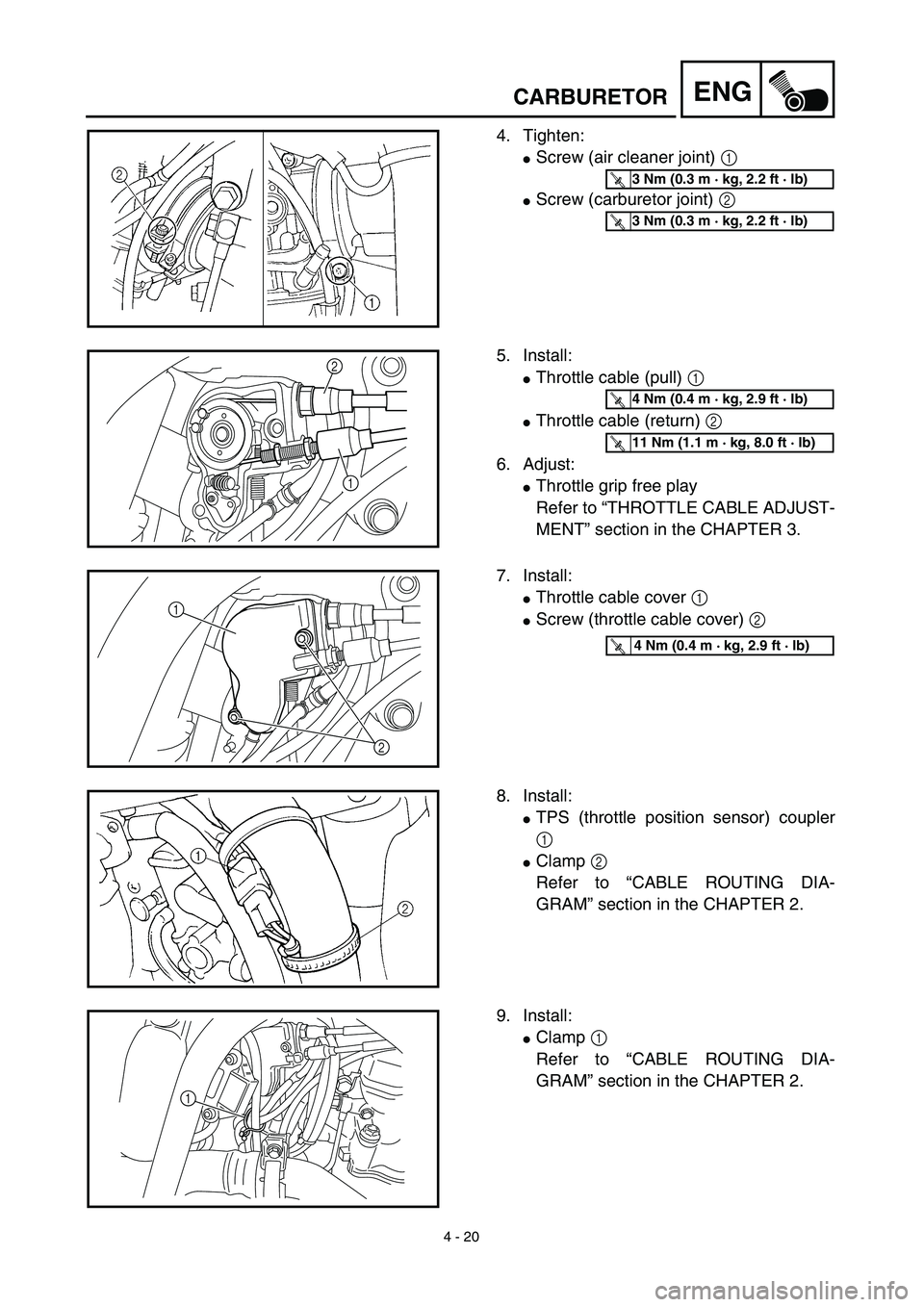
4. Tighten:
�Screw (air cleaner joint) 1
�Screw (carburetor joint) 2
T R..3 Nm (0.3 m · kg, 2.2 ft · lb)
T R..3 Nm (0.3 m · kg, 2.2 ft · lb)
5. Install:
�Throttle cable (pull) 1
�Throttle cable (return) 2
6. Adjust:
�Throttle grip free play
Refer to “THROTTLE CABLE ADJUST-
MENT” section in the CHAPTER 3.
2
1
T R..4 Nm (0.4 m · kg, 2.9 ft · lb)
T R..11 Nm (1.1 m · kg, 8.0 ft · lb)
7. Install:
�Throttle cable cover 1
�Screw (throttle cable cover) 2
2 1
T R..4 Nm (0.4 m · kg, 2.9 ft · lb)
8. Install:
�TPS (throttle position sensor) coupler
1
�Clamp 2
Refer to “CABLE ROUTING DIA-
GRAM” section in the CHAPTER 2.
9. Install:
�Clamp 1
Refer to “CABLE ROUTING DIA-
GRAM” section in the CHAPTER 2.
1
CARBURETOR
Page 342 of 754
4 - 21
ENGCAMSHAFTS
CAMSHAFTS
CYLINDER HEAD COVER
Extent of removal:1 Cylinder head cover removal
Extent of removal Order Part name Q’ty Remarks
CYLINDER HEAD COVER
REMOVAL
Preparation for removal Seat and fuel tank Refer to “SEAT, FUEL TANK AND SIDE
COVERS” section.
Carburetor Refer to “CARBURETOR” section.
1 Spark plug 1
2 Engine upper bracket (right) 1
3 Engine upper bracket (left) 1
4 Cylinder head breather hose 1
5 Oil tank breather hose 1
6 Bolt (cylinder head cover) 2
7 Cylinder head cover 1
8 Gasket 1
9 Timing chain guide (upper) 1
1
Page 358 of 754
4 - 29
ENGCYLINDER HEAD
CYLINDER HEAD
CYLINDER HEAD
Extent of removal:1 Cylinder head removal
NOTE:
Tighten the cylinder head bolts to 30 Nm (3.0 m · kg, 22 ft · lb) in the proper tightening sequence, remove and
retighten the cylinder head bolts to 20 Nm (2.0 m · kg, 14 ft · lb) in the proper tightening sequence, and then
tighten the cylinder head bolts further to reach the specified angle 180˚ in the proper tightening sequence.
Extent of removal Order Part name Q’ty Remarks
CYLINDER HEAD REMOVAL
Preparation for removal Seat and fuel tank Refer to “SEAT, FUEL TANK AND SIDE
COVERS” section.
Exhaust pipe and silencer Refer to “EXHAUST PIPE AND
SILENCER” section.
Radiator Refer to “RADIATOR” section.
Carburetor Refer to “CARBURETOR” section.
Camshaft Refer to “CAMSHAFTS” section.
1 Oil delivery pipe 1
2 Nut 2
3* Bolt (L = 150 mm) 2
Refer to NOTE.
4* Bolt (L = 160 mm) 2
5 Cylinder head 1
6 Gasket 1
7 Dowel pin 2
8 Timing chain guide (front) 1
1
Page 466 of 754
4 - 83
ENGENGINE REMOVAL
EC4M0000
ENGINE REMOVAL
Extent of removal Order Part name Q’ty Remarks
ENGINE REMOVAL
Preparation for removal Hold the machine by placing the
suitable stand under the frame.
WARNING
Support the machine securely so there is no
danger of it falling over.
Drain the engine oil Refer to “ENGINE OIL REPLACEMENT”
section in the CHAPTER 3.
Seat and fuel tank Refer to “SEAT, FUEL TANK AND SIDE
COVERS” section.
Carburetor Refer to “CARBURETOR” section.
Exhaust pipe and silencer Refer to “EXHAUST PIPE AND
SILENCER” section.
Clutch cable and guide Disconnect at the engine side.
Radiator Refer to “RADIATOR” section.
Shift pedal Refer to “AC MAGNETO AND
STARTER CLUTCH” section.
Cylinder head breather hose and
oil tank breather hoseRefer to “CAMSHAFTS” section.
Ignition coil
Disconnect the AC magneto lead.
Page 692 of 754
6 - 21
–+ELECTPS (THROTTLE POSITION SENSOR) SYSTEM
3. Inspect:
�TPS coil variable resistance
Check that the resistance in increased
as the throttle grip is moved from the
full close position to the full open posi-
tion.
Out of specification → Replace.
Tester (+) lead → Yellow lead 1
Tester (–) lead → Black lead 2
TPS coil variable
resistanceTester selec-
tor position
Full closedFull opened
kΩ × 1 0 ~ 2 kΩ at
20 ˚C
(68 ˚F)4 ~ 6 kΩ at
20 ˚C
(68 ˚F)
TPS REPLACEMENT AND ADJUSTMENT
1. Remove:
�TPS coupler
�Screw (TPS) 1
�TPS 2
NOTE:
Loosen the screws (TPS) using the T25 bit.
2. Replace:
�TPS
3. Install:
�TPS 1
�Screw (TPS) 2
�TPS coupler
NOTE:
�Align the slot a in the TPS with the projec-
tion b on the carburetor.
�Temporarily tighten the screws (TPS).
12
21
b
a
Page 704 of 754

7 - 1
TUN
EC700000
TUNING
EC710000
ENGINE
Carburetor setting
�
The air/fuel mixture will vary depending on
atmospheric conditions. Therefore, it is nec-
essary to take into consideration the air pres-
sure, ambient temperature, humidity, etc.,
when adjusting the carburetor.
�
Perform a test run to check for proper engine
performance (e.g., throttle response) and
spark plug(-s) discoloration or fouling. Use
these readings to determine the best possi-
ble carburetor setting.
NOTE:
It is recommended to keep a record of all car-
buretor settings and external conditions (e.g.,
atmospheric conditions, track/surface condi-
tions, lap times) to make future carburetor set-
ting easier.
WARNING
�
The carburetor is a part of the fuel line.
Therefore, be sure to install it in a well-
ventilated area, away from flammable
objects and any sources of fire.
�
Never look into the carburetor intake.
Flames may shoot out from the pipe if the
engine backfires while it is being started.
Gasoline may be discharged from the
accelerator pump nozzle when the carbu-
retor has been removed.
SETTING


 in the proper tightening sequenc")

