Page 320 of 754
4 - 10
ENGCARBURETOR
Extent of removal Order Part name Q’ty Remarks
HNeedle valve 1
IMain jet 1
JNeedle jet 1
KSpacer 1
LPilot jet 1
MStarter jet 1
NPush rod 1 Pull the push rod.
OThrottle shaft assembly 1
PPush rod link lever assembly 1
QPilot air jet 1
RCold starter plunger 1
1
Page 322 of 754
} 1 except when changing
the TPS (throttle position sensor) due to
failure because it will")
4 - 11
ENGCARBURETOR
EC466020
HANDLING NOTE
CAUTION:
Do not loosen the screws {TPS (throttle
position sensor)} 1 except when changing
the TPS (throttle position sensor) due to
failure because it will cause a drop in
engine performance.
1
REMOVAL POINTS
Pilot screw
1. Remove:
�Pilot screw 1
NOTE:
To optimize the fuel flow at a small throttle
opening, each machine’s pilot screw has been
individually set at the factory. Before removing
the pilot screw, turn it in fully and count the
number of turns. Record this number as the
factory-set number of turns out.
INSPECTION
Carburetor
1. Inspect:
�Carburetor body
Contamination → Clean.
NOTE:
�Use a petroleum based solvent for cleaning.
Blow out all passages and jets with com-
pressed air.
�Never use a wire.
2. Inspect:
�Main jet 1
�Pilot jet 2
�Needle jet 3
�Starter jet 4
�Pilot air jet 5
�Leak jet 6
Damage → Replace.
Contamination → Clean.
NOTE:
�Use a petroleum based solvent for cleaning.
Blow out all passages and jets with com-
pressed air.
�Never use a wire.
Page 324 of 754
4 - 12
ENGCARBURETOR
Needle valve
1. Inspect:
�Needle valve 1
�Valve seat 2
Grooved wear a → Replace.
Dust b → Clean.
EC464300
Throttle valve
1. Check:
�Free movement
Stick → Repair or replace.
Insert the throttle valve 1 into the car-
buretor body, and check for free move-
ment.
EC464400
Jet needle
1. Inspect:
�Jet needle 1
Bends/wear → Replace.
�Clip groove
Free play exists/wear → Replace.
�Clip position
Standard clip position:
No.4 Groove
EC464511
Float height
1. Measure:
�Float height a
Out of specification → Adjust.
Float height:
8.0 mm (0.31 in)
Page 326 of 754
4 - 13
ENGCARBURETOR
Measurement and adjustment steps:
�Hold the carburetor in an upside down
position.
NOTE:
�Slowly tilt the carburetor in the opposite
direction, then take the measurement
when the needle valve aligns with the float
arm.
�If the carburetor is level, the weight of the
float will push in the needle valve, result-
ing in an incorrect measurement.
�Measure the distance between the mating
surface of the float chamber and top of the
float using a vernier calipers.
NOTE:
The float arm should be resting on the nee-
dle valve, but not compressing the needle
valve.
�If the float height is not within specifica-
tion, inspect the valve seat and needle
valve.
�If either is worn, replace them both.
�If both are fine, adjust the float height by
bending the float tab b on the float.
�Recheck the float height.
EC464600
Float
1. Inspect:
�Float 1
Damage → Replace.
Starter plunger
1. Inspect:
�Cold starter plunger 1
�Hot starter plunger 2
Wear/damage → Replace.
Page 328 of 754
4 - 14
ENG
Accelerator pump
1. Inspect:
�Diaphragm (accelerator pump) 1
�Spring 2
�Cover 3
�O-ring 4
�Push rod 5
Tears (diaphragm)/damage → Replace.
Dirt → Clean.
2. Inspect:
�Throttle shaft 1
�Spring 2
�Lever 1 3
�Spring 1 4
�Lever 2 5
�Spring 2 6
Dirt → Clean.
12
3456
Air cut valve
1. Inspect:
�Diaphragm (air cut valve) 1
�Spring (air cut valve) 2
�Air cut valve cover 3
�O-ring 4
Tears (diaphragm)/damage → Replace.
1
23
4
ASSEMBLY AND INSTALLATION
Carburetor
1. Install:
�Cold starter plunger 1
2. Install:
�Pilot air jet 1
1
CARBURETOR
Page 330 of 754
4 - 15
ENGCARBURETOR
3. Install:
�Spring 1 1
�Lever 1 2
To lever 2 3.
NOTE:
Make sure the spring 1 fits on the stopper a of
the lever 2.
a
31
2
4. Install:
�Spring 2 1
To lever 2 2.
1
2
5. Install:
�Push rod link lever assembly 1
NOTE:
Make sure the stopper a of the spring 2 fits
into the recess b in the carburetor.
1
a b
6. Install:
�Plain washer 1
�Circlip 2
21
7. Install:
�Spring 1
To throttle shaft 2.
NOTE:
Install the bigger hook a of the spring fits on
the stopper b of the throttle shaft pulley.
Page 332 of 754
4 - 16
ENGCARBURETOR
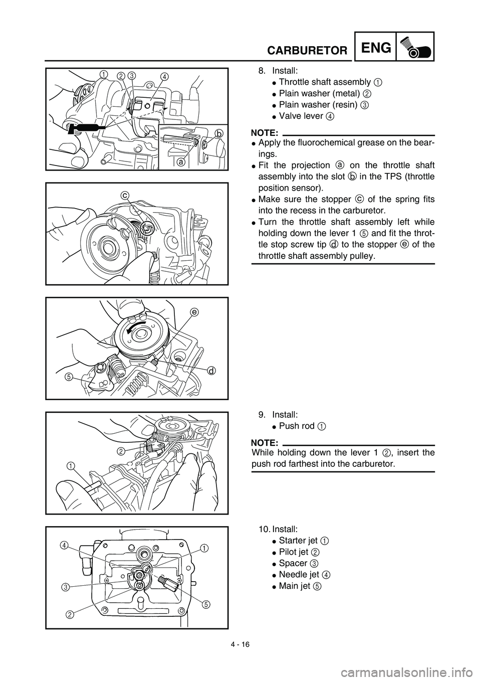
8. Install:
�Throttle shaft assembly 1
�Plain washer (metal) 2
�Plain washer (resin) 3
�Valve lever 4
NOTE:
�Apply the fluorochemical grease on the bear-
ings.
�Fit the projection a on the throttle shaft
assembly into the slot b in the TPS (throttle
position sensor).
�Make sure the stopper c of the spring fits
into the recess in the carburetor.
�Turn the throttle shaft assembly left while
holding down the lever 1 5 and fit the throt-
tle stop screw tip d to the stopper e of the
throttle shaft assembly pulley.
1
23
4
b
a
c
e
d
5
9. Install:
�Push rod 1
NOTE:
While holding down the lever 1 2, insert the
push rod farthest into the carburetor.12
10. Install:
�Starter jet 1
�Pilot jet 2
�Spacer 3
�Needle jet 4
�Main jet 5
Page 334 of 754
4 - 17
ENGCARBURETOR
11. Install:
�Needle valve 1
�Float 2
�Float pin 3
NOTE:
�After installing the needle valve to the float,
install them to the carburetor.
�Check the float for smooth movement.
12. Install:
�Pilot screw 1
�Spring 2
�Washer 3
�O-ring 4
* Except for USANote the following installation points:
�Turn in the pilot screw until it is lightly
seated.
�Turn out the pilot screw by the number of
turns recorded before removing.
Pilot screw:
1-3/4 turns out (example)
*1-1/2 turns out (example)
13. Install:
�O-ring
�Leak jet 1
�Float chamber 2
�Screw (float chamber) 3
�Cable holder (throttle stop screw cable)
4
�Hose holder (carburetor breather hose)
5
532 4
5
1
14. Install:
�Diaphragm (air cut valve) 1
�Spring (air cut valve) 2
�O-ring 3
�Air cut valve cover 4
�Screw (air cut valve cover) 5
1
2
3
5
4