Page 592 of 754

5 - 44
CHASHANDLEBAR
8. Install:
�Start switch 1
�Master cylinder 2
�Master cylinder bracket 3
�Bolt (master cylinder bracket) 4
�Clamp 5
NOTE:
�The start switch and master cylinder bracket
should be installed according to the dimen-
sions shown.
�Install the bracket so that the arrow mark a
faces upward.
�First tighten the bolt on the upper side of the
master cylinder bracket, and then tighten the
bolt on the lower side.
T R..9 Nm (0.9 m · kg, 6.5 ft · lb)
Zero mm
(Zero in)Zero mm
(Zero in)
9. Install:
�Lights switch 1
T R..2 Nm (0.2 m · kg, 1.4 ft · lb)
10. Install:
�“ENGINE STOP” button 1
�Clutch lever holder 2
�Bolt (clutch lever holder) 3
�Hot starter lever holder 4
�Bolt (hot starter lever holder) 5
�Clamp 6
NOTE:
�The “ENGINE STOP” button, clutch lever
holder and clamp should be installed accord-
ing to the dimensions shown.
�Pass the “ENGINE STOP” button lead in the
middle of the clutch lever holder.
T R..4 Nm (0.4 m · kg, 2.9 ft · lb)
T R..4 Nm (0.4 m · kg, 2.9 ft · lb)
Page 642 of 754

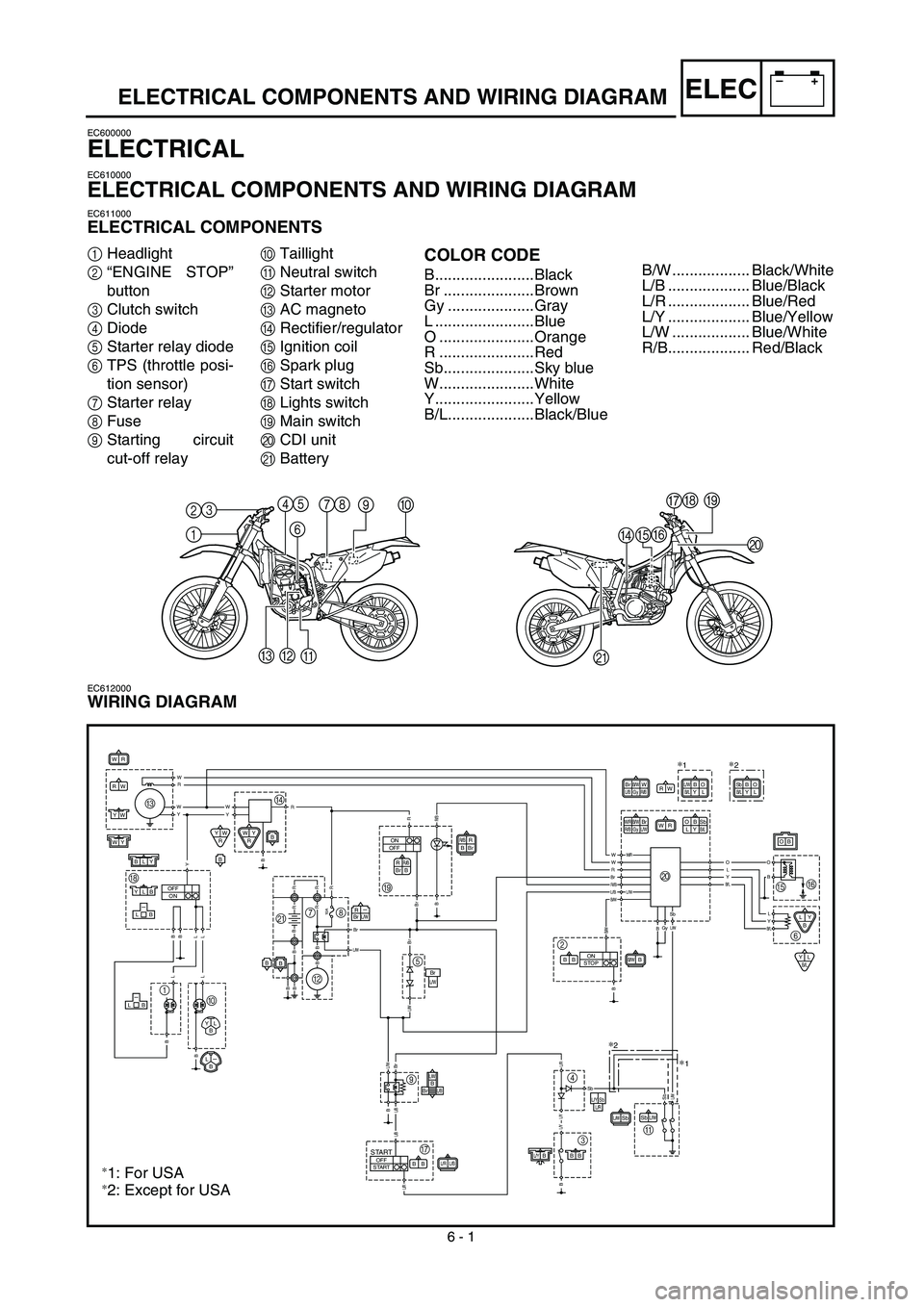
6 - 1
–+ELEC
ELECTRICAL COMPONENTS AND WIRING DIAGRAM
EC600000
ELECTRICAL
EC610000
ELECTRICAL COMPONENTS AND WIRING DIAGRAM
EC611000
ELECTRICAL COMPONENTS
1
Headlight
2
“ENGINE STOP”
button
3
Clutch switch
4
Diode
5
Starter relay diode
6
TPS (throttle posi-
tion sensor)
7
Starter relay
8
Fuse
9
Starting circuit
cut-off relay
0
Taillight
A
Neutral switch
B
Starter motor
C
AC magneto
D
Rectifier/regulator
E
Ignition coil
F
Spark plug
G
Start switch
H
Lights switch
I
Main switch
J
CDI unit
K
Battery
COLOR CODE
B.......................Black
Br .....................Brown
Gy ....................Gray
L .......................Blue
O ......................Orange
R ......................Red
Sb.....................Sky blue
W......................White
Y.......................Yellow
B/L....................Black/Blue
EC612000
WIRING DIAGRAM
1 2345
678
90
A B
CDEFGH
I
J
K
WR
WR
R
BR/BBr
R
BR/BBr
RW
L/RL/BBB
SbL/W
WY
YW
L/YBBB
WY
RYW
R
LY
B
YLB/L
B
B
ON
OFF
10A
BB
OFF
ON
OFF
STARTSTART
R-BrL/W
BLY
YLB-LB
B
BrL/W
BrL/W
L/B-LB
YL
B
L-B
L/WSb
B/WBBB
W/RB/W
R/BGyBrL/W
ON
STOP
OB
LYSbB/L
W RBrB/W
L/BGyWR/B
B O
L/YSbL/R
R W
Y W
Y W
Y B
B
L
L L
L B
B
B
RRR/B
B Br B
B B B B
L/W
R
R
R R B
R
BrBr
L/W L/W
Br B
L/B
L/B
L/R
Br
R/B
L/B L/W
B/W
W W/RW
RO
L
Y
B/L
O
B
L
Y
B/LSbL/WB/W
B
L/R L/Y L/Y
B
SbSbL/W
BGy
SbBB/LYO
L
∗2
O B
L YL/W
B/L
∗1
C
HD
BI
5
9
G3 4
A 2J
EF
6 7
K8
1
0
∗
2
∗1
∗2: Except for USA
∗1: For USA
B/W .................. Black/White
L/B ................... Blue/Black
L/R ................... Blue/Red
L/Y ................... Blue/Yellow
L/W .................. Blue/White
R/B................... Red/Black
Page 698 of 754
–+ELEC
6 - 24
LIGHTING SYSTEM
LIGHTING SYSTEM
INSPECTION STEPS
Refer to the following flow chart when inspecting the ignition system for possible problems.
NOTE:
�Replace the bulb and/or bulb socket.
1) Seat
2) Fuel tank
�Use the following special tool.
Check the bulb and bulb
socket.Replace the bulb and/
or bulb socket.
Check the lights switch. Replace.
Check the AC magneto. Lighting coil Replace.
Check the entire lighting sys-
tem proper for connections.Repair or replace.
Check the rectifier/regulator.Out-put
voltageReplace.
Pocket tester:
YU-3112-C/90890-03112Inductive tachometer:
YU-8036-B
Engine tachometer:
90890-03113
OK
OK
OK
OK
No good
No good
Improperly connected
No good
No good
Page 702 of 754
6 - 25
–+ELECLIGHTING SYSTEM
LIGHTS SWITCH INSPECTION
1. Inspect:
�Lights switch conduct
No continuous while being → Replace.
Continuous while being OFF → Replace. Tester (+) lead → Yellow lead 1
Tester (–) lead → Blue lead 2
Y
1L
2Tester selec-
tor position
Ω × 1
OFF
AC MAGNETO INSPECTION
1. Inspect:
�Lighting coil resistance
Out of specification → Replace.
RECTIFIER/REGULATOR INSPECTION
1. Connect the battery leads.
2. Start the engine.
3. Turn on the headlight and taillight by turn-
ing on the lights switch.
4. Inspect:
�Out-put voltage
Out of specification → Replace rectifier/
regulator. Tester (+) lead → Yellow lead 1
Tester (–) lead → Ground 2
Lighting coil
resistanceTester selector
position
0.224 ~ 0.336 Ω
at 20 ˚C (68 ˚F)Ω × 1
Tester (+) lead → Yellow lead 1
Tester (–) lead → Black lead 2
Out-put voltageTester selector
position
13.0 ~ 14.0 V at
5,000 r/minACV-20
R
BW
Y1
2