2003 YAMAHA WR 250F clutch
[x] Cancel search: clutchPage 450 of 860

4 - 125
ENGCLUTCH
EC4A3000REMOVAL POINTS
Clutch boss
1. Remove:
Nut
1
Lock washer
2
Clutch boss
3
NOTE:Straighten the lock washer tab and
use the clutch holding tool
4 to hold
the clutch boss.
ÈFor USA and CDN
ÉExcept for USA and CDN
Clutch holding tool:
YM-91042/90890-04086
ÈÉ
EC4A4000INSPECTIONEC484100Clutch housing and boss
1. Inspect:
Clutch housing
1
Cracks/wear/damage
→
Replace.
Clutch boss
2
Scoring/wear/damage
→
Replace.
EC484201Primary driven gear
1. Check:
Circumferential play
Free play exists
→ Replace.
Gear teeth
a
Wear/damage
→ Replace.
Clutch spring
1. Measure:
Clutch spring free length
a
Out of specification
→
Replace springs as a set.
Clutch spring free
length:
37.0 mm (1.46 in)
36.0 mm (1.42 in)
POINTS DE DEPOSE
Noix d’embrayage
1. Déposer:
Ecrou 1
Rondelle-frein 2
Noix d’embrayage 3
N.B.:
Redresser la rondelle-frein et utiliser
l’outil de poignée d’embrayage 4 pour
maintenir la noix d’embrayage.
È
USA et CDN
É
Excepté USA et CDN
Outil de poignée
d’embrayage:
YM-91042/90890-04086
CONTROLE
Cloche et noix d’embrayage
1. Contrôler:
Cloche d’embrayage 1
Craquelures/usure/endommage-
ment → Ramplacer.
Noix d’embrayage 2
Rayures/usure/endommagement
→ Ramplacer.
Pignon mené primaire
1. Contrôler:
Jeu circonférentiel
Jeu → Ramplacer.
Dent
a
Usure/endommagement → Ram-
placer.
Ressort d’embrayage
1. Mesurer:
Longueur libre de ressort
d’embrayage
a
Hors spécification → Ramplacer
tous les ressorts.
Longueur libre de ressort
d’embrayage:
37,0 mm (1,46 in)
36,0 mm (1,42 in)
EMBRAYAGE
Page 452 of 860

4 - 127
ENGCLUTCH
Friction plate
1. Measure:
Friction plate thickness
Out of specification
→
Replace friction plate as a set.
Measure at all four points.
Friction plate thickness:
2.9 ~ 3.1 mm
(0.114 ~ 0.122 in)
2.7 mm (0.106 in)
EC484600Clutch plate
1. Measure:
Clutch plate warpage
Out of specification
→
Replace clutch plate as a set.
Use a surface plate
1 and
thickness gauge
2.
Warp limit:
0.1 mm (0.004 in)
Push lever shaft
1. Inspect:
Push lever shaft
1
Wear/damage
→ Replace.
Push rod
1. Inspect:
Push rod 1
1
Bearing
2
Washer
3
Push rod 2
4
Ball
5
Wear/damage/bend
→
Replace.
Disque de friction
1. Mesurer:
Epaisseur de disque de friction
Hors-spécification → Changer
tous les disques de friction.
Mesurer chaque disque en quatre
endroits.
Epaisseur de disque de
friction:
2,9 à 3,1 mm
(0,114 à 0,122 in)
2,7 mm (0,106 in)
Disque d’embrayage
1. Mesurer:
Voile de disque d’embrayage
Hors spécification → Ramplacer
tous les disques d’embrayage.
Utiliser une plaque à surfacer 1
et une jauge d’épaisseur 2.
Limite de déformation:
0,1 mm (0,004 in)
Arbre de levier de poussée
1. Contrôler:
Arbre de levier de poussée 1
Usure/endommagement → Ram-
placer.
Tige de poussée
1. Contrôler:
Tige de commande 1 1
Roulement 2
Rondelle 3
Tige de commande 2 4
Bille 5
Usure/endommagement/déforma-
tion → Ramplacer.
EMBRAYAGE
Page 454 of 860

4 - 129
ENGCLUTCH
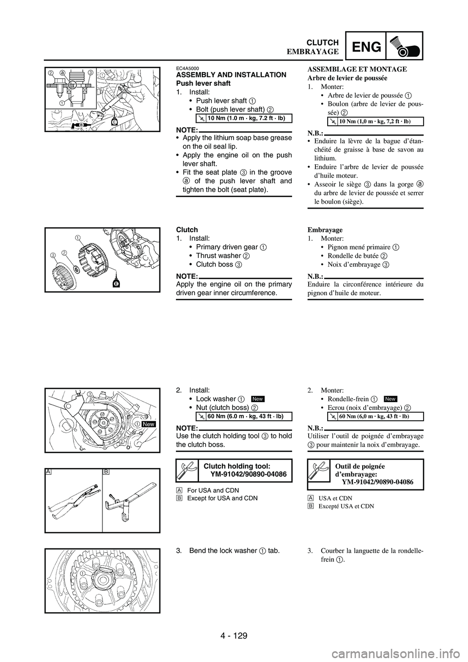
EC4A5000ASSEMBLY AND INSTALLATION
Push lever shaft
1. Install:
Push lever shaft
1
Bolt (push lever shaft)
2
NOTE:Apply the lithium soap base grease
on the oil seal lip.
Apply the engine oil on the push
lever shaft.
Fit the seat plate
3 in the groove
a of the push lever shaft and
tighten the bolt (seat plate).
T R..10 Nm (1.0 m · kg, 7.2 ft · lb)
3
1a2
Clutch
1. Install:
Primary driven gear
1
Thrust washer
2
Clutch boss
3
NOTE:Apply the engine oil on the primary
driven gear inner circumference.
2. Install:
Lock washer
1
Nut (clutch boss)
2
NOTE:Use the clutch holding tool
3 to hold
the clutch boss.
ÈFor USA and CDN
ÉExcept for USA and CDN
T R..60 Nm (6.0 m · kg, 43 ft · lb)
Clutch holding tool:
YM-91042/90890-04086
New
ÈÉ
3. Bend the lock washer
1 tab.
ASSEMBLAGE ET MONTAGE
Arbre de levier de poussée
1. Monter:
Arbre de levier de poussée 1
Boulon (arbre de levier de pous-
sée) 2
N.B.:
Enduire la lèvre de la bague d’étan-
chéité de graisse à base de savon au
lithium.
Enduire l’arbre de levier de poussée
d’huile moteur.
Asseoir le siège 3 dans la gorge
a
du arbre de levier de poussée et serrer
le boulon (siège).
T R..10 Nm (1,0 m · kg, 7,2 ft · lb)
Embrayage
1. Monter:
Pignon mené primaire 1
Rondelle de butée 2
Noix d’embrayage 3
N.B.:
Enduire la circonférence intérieure du
pignon d’huile de moteur.
2. Monter:
Rondelle-frein 1
Ecrou (noix d’embrayage) 2
N.B.:
Utiliser l’outil de poignée d’embrayage
3 pour maintenir la noix d’embrayage.
È
USA et CDN
É
Excepté USA et CDN
T R..60 Nm (6,0 m · kg, 43 ft · lb)
Outil de poignée
d’embrayage:
YM-91042/90890-04086
New
3. Courber la languette de la rondelle-
frein 1.
EMBRAYAGE
Page 456 of 860

4 - 131
ENGCLUTCH
4. Install:
Seat plate
1
Cushion spring
2
NOTE:Install the seat plate with its cham-
fered portion
a facing the clutch
boss
3.
Install the seat plate so that it is not
caught on the step
b.
Install the cushion spring with the
paint
c facing out.
1
2
c
3
a
b
5. Install:
Friction plate 1
1
Clutch plate 1
2
Friction plate 2
3
Clutch plate 2
4
NOTE:Install the clutch plates and friction
plates alternately on the clutch
boss, starting with a friction plate
and ending with a friction plate.
Use the friction plates 1 for the first
and final while paying attention to
the difference in surface pattern.
Apply the engine oil on the friction
plates and clutch plates.
Unlike the clutch plate 2, the clutch
plate 1 has no surface gloss. Use
the clutch plate 1 for the first while
paying attention to the difference in
surface gloss.
6. Install:
Bearing 1
Washer 2
Circlip 3
To push rod 1 4.
NOTE:Apply the engine oil on the bearing
and washer.
New
7. Install:
Push rod 2 1
Ball 2
Push rod 1 3
NOTE:Apply the engine oil on the push rod
1, 2 and ball.
4. Monter:
Plaque d’assise 1
Ressort amortisseur 2
N.B.:
Monter le siège avec son côté chan-
freiné a face à la cloche d’embrayage
3.
Monter le siège de sorte qu’il ne
grippe pas à l’étape b.
Installer le ressort amortisseur avec la
peinture c orientée vers l’extérieur.
5. Monter:
Disque de friction 1 1
Disque d’embrayage 1 2
Disque de friction 2 3
Disque d’embrayage 2 4
N.B.:
Mettre alternatiement les disques
d’embrayage et les disques de friction
en place sur la noix d’embrayage, en
començant par un disque de friction et
en terminant par un disque de friction.
Commencer et terminer par un disque
de friction 1 et être attentif à la diffé-
rence de leur surface.
Appliquer de l’huile moteur sur les
disques de friction et les disques
d’embrayage.
Contrairement au disque de friction 2,
le disque de friction 1 n’a pas de sur-
face brillante. Utiliser d’abord le dis-
que de friction 1 en faisant attention à
la différence de surface.
6. Monter:
Roulement 1
Rondelle 2
Circlip 3
Sur la tige de commande 1 4.
N.B.:
Appliquer de l’huile moteur sur le roule-
ment et la rondelle.
New
7. Monter:
Tige de commande 2 1
Bille 2
Tige de commande 1 3
N.B.:
Appliquer de la graisse de savon au
lithium sur la tige de commande 1, 2 et la
bille.
EMBRAYAGE
Page 458 of 860

4 - 133
ENGCLUTCH
8. Install:
Pressure plate
1
9. Install:
Clutch spring
1
Bolt (clutch spring)
2
NOTE:Tighten the bolts in stage, using a
crisscross pattern.
T R..8 Nm (0.8 m · kg, 5.8 ft · lb)
10. Install:
Dowel pin
1
Gasket (clutch cover)
2
New
11. Install:
Clutch cover
1
Bolt (clutch cover)
NOTE:Tighten the bolts in stage, using a
crisscross pattern.
T R..10 Nm (1.0 m · kg, 7.2 ft · lb)
8. Monter:
Plaque de pression 1
9. Monter:
Ressort d’embrayage 1
Boulon (ressort d’embrayage) 2
N.B.:
Serrer les boulons par étapes dans un
ordre entrecroisé.
T R..8 Nm (0,8 m · kg, 5,8 ft · lb)
10. Monter:
Goujon 1
Joint (couvercle d’embrayage) 2
New
11. Monter:
Couvercle d’embrayage 1
Boulon (couvercle d’embrayage)
N.B.:
Serrer les boulons par étapes, dans un
ordre entrecroisé.
T R..10 Nm (1,0 m · kg, 7,2 ft · lb)
EMBRAYAGE
Page 476 of 860

4 - 151
ENGBALANCER
BALANCER
Extent of removal:
1 Balancer shaft drive gear
2 Balancer shaft
Extent of removal Order Part name Q’ty Remarks
BALANCER REMOVAL
Preparation for removal Primary driven gear Refer to “CLUTCH” section.
Right crankcase cover Refer to “OIL FILTER ELEMENT, WATER PUMP
AND RIGHT CRANKCASE COVER” section.
Stator Refer to “AC MAGNETO AND STARTER CLUTCH”
section.
1 Nut (primary drive gear) 1
Refer to “REMOVAL POINTS”.
2 Nut (balancer shaft driven gear) 1
3 Lock washer 1
4 Primary drive gear 1
5 Balancer shaft drive gear 1
6 Lock washer 1
7 Balancer shaft driven gear 1
8 Balancer shaft 1 Refer to “REMOVAL POINTS”.
1
2
2
Page 484 of 860

4 - 159
ENGOIL PUMP
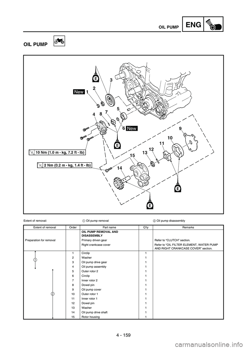
OIL PUMP
Extent of removal:
1 Oil pump removal
2 Oil pump disassembly
Extent of removal Order Part name Q’ty Remarks
OIL PUMP REMOVAL AND
DISASSEMBLY
Preparation for removal Primary driven gear Refer to “CLUTCH” section.
Right crankcase cover Refer to “OIL FILTER ELEMENT, WATER PUMP
AND RIGHT CRANKCASE COVER” section.
1 Circlip 1
2 Washer 1
3 Oil pump drive gear 1
4 Oil pump assembly 1
5 Outer rotor 2 1
6 Circlip 1
7 Inner rotor 2 1
8 Dowel pin 1
9 Oil pump cover 1
10 Outer rotor 1 1
11 Inner rotor 1 1
12 Dowel pin 1
13 Washer 1
14 Oil pump drive shaft 1
15 Rotor housing 1
2
1
Page 506 of 860

4 - 181
ENGKICK SHAFT AND SHIFT SHAFT
2. Install:
Shift lever assembly
1
To shift guide
2.
3. Install:
Shift lever assembly
1
Shift guide
2
NOTE:The shift lever assembly is
installed at the same time as the
shift guide.
Apply the engine oil on the bolt
(segment) shaft.
4. Install:
Bolt (shift guide)
1
T R..10 Nm (1.0 m · kg, 7.2 ft · lb)
Shift shaft
1. Install:
Roller
1
Collar
2
Torsion spring
3
Shift shaft
4
NOTE:Apply the engine oil on the roller and
shift shaft.
2. Install:
Shift pedal
Refer to “AC MAGNETO AND
STARTER CLUTCH” section.
Kick shaft assembly
1. Install:
Kick gear
1
Washer
2
Circlip
3
Ratchet wheel
4
Spring
5
Washer
6
Circlip
7
To kick shaft
8.
NOTE:Apply the molybdenum disulfide oil
on the inner circumferences of the
kick gear and ratchet wheel.
Align the punch mark
a on the
ratchet wheel with the punch mark
b on the kick shaft.
New
New
2. Monter:
Levier de sélecteur complet 1
Au guide de sélecteur 2.
3. Monter:
Levier de sélecteur complet 1
Guide de sélecteur 2
N.B.:
Le levier de sélecteur complet se
monte en même temps que le guide
sélecteur.
Appliquer l’huile sur l’axe de boulon
(barillet).
4. Monter:
Boulon (guide de sélecteur) 1
T R..10 Nm (1,0 m · kg, 7,2 ft · lb)
Arbre de sélecteur
1. Monter:
Rouleau 1
Collerette 2
Ressort de torsion 3
Arbre de sélecteur 4
N.B.:
Appliquer l’huile sur le rouleau et l’arbre
de sélecteur.
2. Monter:
Pédale de sélecteur
Se reporter à la section
“MAGNETO CA ET ROCHET
DE DEMARRAGE”.
Arbre de kick complet
1. Monter:
Pignon de kick 1
Rondelle 2
Circlip 3
Rochet 4
Ressort 5
Rondelle 6
Circlip 7
Sur l’arbre de kick 8.
N.B.:
Appliquer de l’huile de disulfure de
mobdylène sur les pourtours du
pignon de kick et du rochet.
Aligner le repère poinçonné a du
rochet et le repère poinçonné b de
l’arbre de kick.
New
New
ARBRE DE KICK ET ARBRE DE SELECTEUR