Page 286 of 340
5 - 10
CHASSTEERING
EC560000
STEERING
LS
LS
T R..TIGHTENING STEPS:
•Tighten ring nut.
38 Nm (3.8 m • kg, 27 ft • Ib)
•Loosen it completely.
•Retighten it.
1 Nm (0.1 m • kg, 0.7 ft • Ib)
T R..40 Nm (4.0 m • kg, 29 ft • Ib)
5 9681076 43
21
Extent of removal:1 Under bracket removal2 Bearing removal
Extent of removal Order Part name Q’ty Remarks
STEERING REMOVAL
WARNING
Support the machine securely so there is nodanger of it falling over.
Preparation for removal Hold the machine by placing the
suitable stand under the engine.
Front fork Refer to “FRONT FORK” section.
1 Steering stem bolt 1
2 Handle crown 1
3 Ring nut 1 Use special tool.
Refer to “STEERING HEAD INSPEC-
TION AND ADJUSTMENT” section in
the CHAPTER 3.
4 Ball race cover 1
5 Under bracket 1
6 Bearing inner race 2
7 Upper bearing ball 19
8 Lower bearing ball 16
9 Dust seal 1
10 Bearing outer race 2
2
1
Page 288 of 340
5 - 11
CHASSWINGARM
EC570000
SWINGARM
Extent of removal:1 Swingarm removal2 Rear shock absorber removal
Extent of removal Order Part name Q’ty Remarks
SWINGARM REMOVAL
WARNING
Support the machine securely so there is nodanger of it falling over.
Preparation for removal Hold the machine by placing the
suitable stand under the engine.
Rear wheel Refer to “FRONT WHEEL AND REAR
WHEEL” section.
Rear fender
Drive chain
1 Cotter pin 2
2 Pin 2
3 Rear shock absorber 1
4 Pivot shaft 1 Hold the swingarm.
5 Swing arm 1
6 Drive chain guide 1
7 Drive chain guard 1
8 Drive chain support 1
1
2
Page 292 of 340

6 - 1
–+ELEC
12
3
456
7
0
98
A
B
F
EC
D
ELECTRICAL COMPONENTS AND WIRING DIAGRAM
EC600000
ELECTRICAL
EC610000
ELECTRICAL COMPONENTS AND WIRING DIAGRAM
EC611000
ELECTRICAL COMPONENTS
1
Main switch
2
“ENGINE STOP”
switch
3
Thermo switch
4
Ignition coil
5
CDI unit
6
Battery
7
Rectifier/regulator
8
Neutral switch
9
CDI magneto
0
Carburetor heater
A
Starter relay
B
Fuse
C
Start switch
D
Spark plug
E
Starter motor
F
Starting circuit cut-off
relay
COLOR CODE
B ...................... Black
Br .................... Brown
G ..................... Green
O ..................... Orange
R ..................... Red
Sb .................... Sky blue
W ..................... White
Y ...................... Yellow
EC612000
WIRING DIAGRAM
G/WB/RW/LW/RBr G
RW
B/WBr BRB/WBBrR
B/WB BB
BR/WBr B
GG/W
B/W
B/W
BrB/RWWOO
B
BW/LY/RR
W
B
B
R
W/RY/R
OFF RUNB
Y/R
Y
Y
OBO BY/RYB B
Sb
W W
Sb
ON OFF
OFFON
Y
BB
Y/R
Br
Br
B
B
R
RR
R
B
R/WR/W
R/WR/W
R/W
Sb
Sb
RB
R/WB R
Y/RRB W
B/WB
R/W
R/W
R/W
Sb
9
8
1 B5
4
D
2 3
=A
E 6
C
F 7
B/R ................... Black/Red
B/W .................. Black/White
G/W.................. Green/White
R/W .................. Red/White
W/L .................. White/Blue
W/R .................. White/Red
Y/R ................... Yellow/Red
Page 294 of 340
–+ELEC
6 - 2
IGNITION SYSTEM
EC620000
IGNITION SYSTEM
INSPECTION STEPS
Use the following steps for checking the possibility of the malfunctioning engine being attributable to
ignition system failure and for checking the spark plug which will not spark.
NOTE:
�
Remove the following parts before inspection.
1) Seat
2) Fuel tank
�
Use the following special tools in this inspection.
Spark gap testClean or replace
spark plug.
Check entire ignition
system for connection.Repair or replace.
Check main switch. Replace.
Check “ENGINE STOP”
switch.Replace.
Check ignition coil. Primary coil Replace.
Secondary coil Replace.
Check CDI magneto. Pickup coil Replace.
Source coil Replace.
Replace CDI unit.
Dynamic spark tester:
YM-34487
Ignition checker:
90890-06754
Pocket tester:
YU-3112-C/90890-03112
No Spark
OK
OK
OK
OK
Spark
No good
No good
No good
No good
No good
No good
OK
No good
Page 298 of 340
6 - 3
–+ELEC
IGNITION SYSTEM
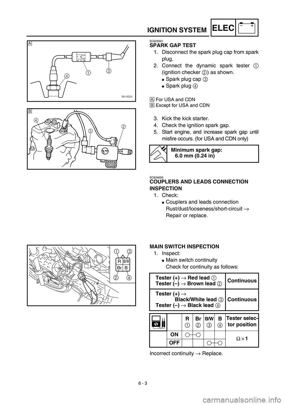
EC622001
SPARK GAP TEST
1. Disconnect the spark plug cap from spark
plug.
2. Connect the dynamic spark tester
1
(ignition checker
2
) as shown.
�
Spark plug cap
3
�
Spark plug
4
Å
For USA and CDN
ı
Except for USA and CDN
3. Kick the kick starter.
4. Check the ignition spark gap.
5. Start engine, and increase spark gap until
misfire occurs. (for USA and CDN only)
Minimum spark gap:
6.0 mm (0.24 in)
Å
ı
EC624000
COUPLERS AND LEADS CONNECTION
INSPECTION
1. Check:
�
Couplers and leads connection
Rust/dust/looseness/short-circuit
→
Repair or replace.
MAIN SWITCH INSPECTION
1. Inspect:
�
Main switch continuity
Check for continuity as follows:
Incorrect continuity
→
Replace.
Tester (+)
→
Red lead
1
Tester (–)
→
Brown lead
2
Continuous
Tester (+)
→
Black/White lead
3
Tester (–)
→
Black lead
4
Continuous
R
1
Br
2
B/W
3B
4Tester selec-
tor position
ON
Ω × 1
OFF
B/W
BrR
B
1
3
2
4
Page 300 of 340
6 - 4
–+ELECIGNITION SYSTEM
“ENGINE STOP” SWITCH INSPECTION
1. Inspect:
�“ENGINE STOP” switch continuity
No continuous while being pushed → Replace.
Continuous while being free → Replace. Tester (+) lead → Black lead 1
Tester (–) lead → Black lead 2
B
1B
2Tester selec-
tor position
PUSH IN
Ω × 1
FREE
B B
1
2
EC626002
IGNITION COIL INSPECTION
1. Inspect:
�Primary coil resistance
Out of specification → Replace.
2. Inspect:
�Secondary coil resistance
Out of specification → Replace.
NOTE:
When inspecting the secondary coil resis-
tance, remove the spark plug cap.Tester (+) lead → Orange lead 1
Tester (–) lead → Black lead 2
Primary coil
resistanceTester selector
position
0.18 ~ 0.28 Ω at
20 ˚C (68 ˚F)Ω × 1
Tester (+) lead → Spark plug lead 1
Tester (–) lead → Orange lead 2
Secondary coil
resistanceTester selector
position
6.3 ~ 9.5 kΩ at
20 ˚C (68 ˚F)kΩ × 1
Page 304 of 340
6 - 6
–+ELEC
ELECTRIC STARTING SYSTEM
STARTING CIRCUIT CUT-OFF SYSTEM
OPERATION
If the main switch is set to “ON”, the starter
motor can only operate if the following condi-
tion is met:
�The transmission is in neutral (the neutral
switch is closed).
The starting circuit cut-off relay prevents the
starter motor from operating when this condi-
tion has not been met. In this instance, the
starting circuit cut-off relay is open so current
cannot reach the starter motor. When the
above condition has been met the starting cir-
cuit cut-off relay is closed and the engine can
be started by pressing the start switch.
WHEN THE TRANSMISSION IS
IN NEUTRAL
1Battery
2Main fuse
3Main switch
4Start switch
5Starting circuit cut-off relay
6Neutral switch
7Starter relay
8Starter motor
12
M
3
7
54
6 8
ELECTRIC STARTING SYSTEM
Page 316 of 340
6 - 11
–+ELEC
STARTER MOTOR
Extent of removal:1 Starter motor disassembly
Extent of removal Order Part name Q’ty Remarks
STARTER MOTOR REMOVAL
Preparation for removal Drain the engine oil Refer to “ENGINE OIL REPLACEMENT”
section in the CHAPTER 3.
1 Starter motor 1
STARTER MOTOR DISASSEM-
BLY
1Front bracket 1
2Ring 1
3Brush set 1
4Armature assembly 1
5Stator assembly 1
1
ELECTRIC STARTING SYSTEM

•Loosen it completely.
•Retighten it.
1 Nm (0.1 m • kg, 0.7 ft • Ib")