Page 269 of 578

ENG
4 - 12
CULASSE
ZYLINDERKOPF
ZYLINDERKOPF
ZYLINDERKOPFDECKEL UND VENTILDECKEL
Demontage-Arbeiten:1 Zylinderkopfdeckel und Ventildeckel demontieren
Demontage-ArbeitenReihen-
folgeBauteil Anz. Bemerkungen
ZYLINDERKOPFDECKEL UND
VENTILDECKEL DEMONTIE-
REN
Vorbereitung für den
AusbauSitz und Kraftstofftank Siehe unter “SITZ, KRAFTSTOFFTANK
UND SEITENDECKEL” section.
Schalldämpfer Siehe unter “SCHALLDÄMPFER”.
Vergaser Siehe unter “VERGASER”.
C.D.I.-Einheit Vom Rahmen demontieren.
1 Motorhalterung 1
2Zündkerze 1
3 Zylinderkopfdeckel 1
4 Ventildeckel 2
5 Kurbelwellen-Verschlußschraube 1
6Zündeinstell-Verschlußschraube
1
1
CULASSE
CACHE LATÉRAL DE CULASSE ET COUVRE-POUSSOIRS
Organisation de la dépose:1 Dépose du cache latéral de culasse et des couvre-poussoirs
Organisation de la dépose Ordre Nom de pièce QtéRemarques
DÉPOSE DU CACHE LATÉRAL
DE CULASSE ET DES COUVRE-
POUSSOIRS
Préparation à la dépose Selle et réservoir de carburant Se reporter à la section “SELLE, RÉSER-
VOIR DE CARBURANT ET CACHES
LATÉRAUX”.
Pot d’échappement Se reporter à la section “POT D’ÉCHAPPE-
MENT”.
Carburateur Se reporter à la section “CARBURATEUR”.
Bloc CDI Séparer du cadre.
1 Support de moteur 1
2 Bougie 1
3 Cache latéral de culasse 1
4 Cache de poussoir 2
5 Vis d’accès du vilebrequin 1
6 Vis d’accès du repère de distribution 1
1
Page 274 of 578
4 - 15
ENGCYLINDER HEAD
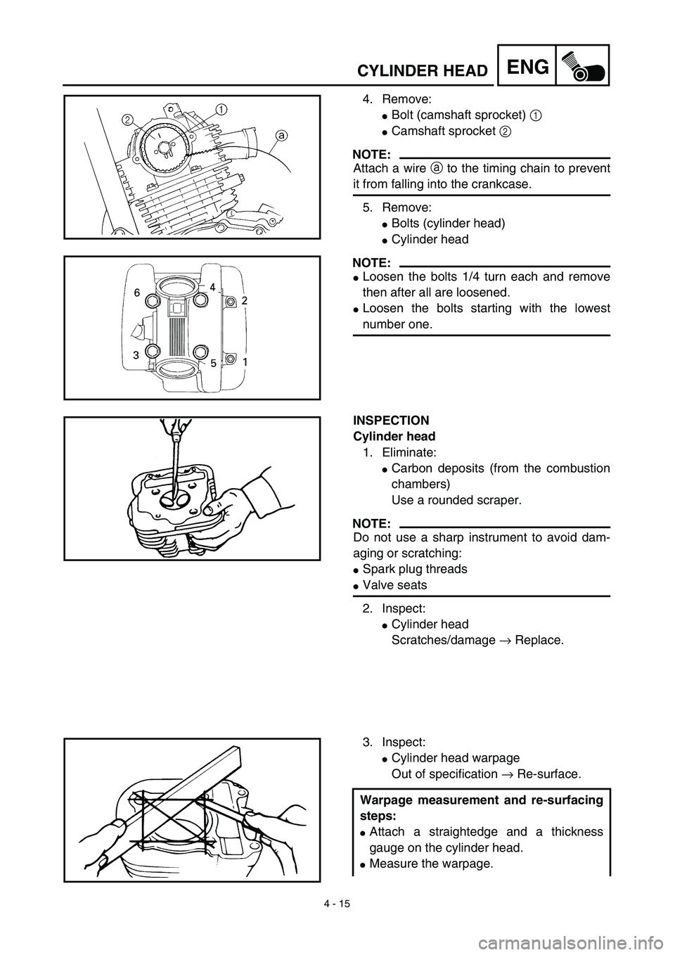
4. Remove:
�Bolt (camshaft sprocket) 1
�Camshaft sprocket 2
NOTE:
Attach a wire a to the timing chain to prevent
it from falling into the crankcase.
5. Remove:
�Bolts (cylinder head)
�Cylinder head
NOTE:
�Loosen the bolts 1/4 turn each and remove
then after all are loosened.
�Loosen the bolts starting with the lowest
number one.
INSPECTION
Cylinder head
1. Eliminate:
�Carbon deposits (from the combustion
chambers)
Use a rounded scraper.
NOTE:
Do not use a sharp instrument to avoid dam-
aging or scratching:
�Spark plug threads
�Valve seats
2. Inspect:
�Cylinder head
Scratches/damage → Replace.
3. Inspect:
�Cylinder head warpage
Out of specification → Re-surface.
Warpage measurement and re-surfacing
steps:
�Attach a straightedge and a thickness
gauge on the cylinder head.
�Measure the warpage.
Page 298 of 578
4 - 27
ENGVALVES AND VALVE SPRINGS
3. Inspect:
�Valve face
Pitting/wear → Grind the face.
�Valve stem end
Mushroom shape or diameter larger
than the body of the stem → Replace.
4. Measure:
�Margin thickness a
Out of specification → Replace.
5. Measure:
�Runout (valve stem)
Out of specification → Replace.
NOTE:
�When installing a new valve always replace
the guide.
�If the valve is removed or replaced always
replace the oil seal.
Margin thickness:
Intake:
0.4 ~ 0.8 mm
(0.0157 ~ 0.0315 in)
Exhaust:
0.8 ~ 1.2 mm
(0.0315 ~ 0.0472 in)
Runout limit:
0.01 mm (0.0004 in)
6. Eliminate:
�Carbon deposits
(from the valve face and valve seat)
7. Inspect:
�Valve seats
Pitting/wear → Reface the valve seat.
Page 316 of 578

4 - 36
ENG
CYLINDER AND PISTON
Piston ring
1. Measure:
�
Ring side clearance
Use a feeler gauge.
Out of specification
→
Replace the pis-
ton and rings as a set.
NOTE:
Clean carbon from the piston ring grooves and
rings before measuring the side clearance.
Side clearance:
Standard
Top
ring0.035 ~ 0.090 mm
(0.0014 ~ 0.0035 in)0.12 mm
(0.0047 in)
2nd
ring0.020 ~ 0.060 mm
(0.0008 ~ 0.0024 in)0.12 mm
(0.0047 in)
2. Position:
�
Piston ring
(in cylinder)
NOTE:
Insert a ring into the cylinder and push it
approximately 40 mm (1.57 in) into the cylin-
der. Push the ring with the piston crown so that
the ring will be at a right angle to the cylinder
bore.
a
40 mm (1.57 in)
3. Measure:
�
Ring end gap
Out of specification
→
Replace.
NOTE:
You cannot measure the end gap on the
expander spacer of the oil control ring. If the oil
control ring rails show excessive gap, replace
all three rings.
End gap:
Standard
Top
ring0.15 ~ 0.30 mm
(0.006 ~ 0.012 in)0.4 mm
(0.016 in)
2nd
ring0.30 ~ 0.45 mm
(0.012 ~ 0.018 in)0.55 mm
(0.022 in)
Oil ring0.20 ~ 0.70 mm
(0.01 ~ 0.03 in)—
Page 361 of 578

ENG
4 - 58
MAGNETO CDI ET ROCHET DE DEMARRAGE
CDI-MAGNETZÜNDER UND STARTERKUPPLUNG
CDI-MAGNETZÜNDER UND STARTERKUPPLUNG
Demontage-Arbeiten:1 Induktionswicklung/Stator demontieren
2 Starterkupplung/Getrieberad-Ausbau
Demontage-ArbeitenReihen-
folgeBauteil Anz. Bemerkungen
LICHTMASCHINE UND STA-
TOR DEMONTIEREN
Vorbereitung für den
AusbauKraftstofftank
1 Lichtmaschinenrotor-Kabel 1
2 Leerlaufschalterleitung 1
3 Kurbelgehäusedeckel (links) 1
4 Mutter (Rotor) 1
Spezialwerkzeug verwenden.
Siehe unter “DEMONTAGEPUNKTE”.
5 Rotor 1
6 Starterkupplung 1
7 Scheibenfeder 1
8 Startergetrieberad 1
9 Unterlegscheibe 1
10 Scheibe (Starterleerlaufrad) 1
11 Starterleerlaufrad 1
12 Kabelführung 1
13 Aufnehmerspule/Ständer-Bau-
gruppe1
2
1
1
MAGNETO CDI ET ROCHET DE DEMARRAGE
Organisation de la dépose:1 Dépose de la bobine d’excitation/stator
2 Dépose du rochet de démarrage et de la roue d’engrenage
Organisation de la dépose Ordre Nom de pièce QtéRemarques
DEPOSE DU MAGNETO CDI ET
DU STATOR
Préparation à la dépose Réservoir de carburant
1 Fil de magnéto CDI 1
2Câble de commutateur de point mort 1
3 Demi-carter gauche 1
4Écrou (rotor) 1 Utiliser l’outil spécial.
Se reporter à la section “PIÈCES À DÉPO-
SER”. 5 Rotor 1
6 Rochet de démarrage 1
7 Clavette demi-lune 1
8 Pignon roue de démarreur 1
9 Rondelle plate 1
10 Plaque (pignon de ralenti de démar-
reur)1
11 Pignon de ralenti de démarreur 1
12 Guide de fil 1
13 Bobine d’excitation/ensemble stator 1
2
1
1
Page 370 of 578
4 - 63
ENG
ENGINE REMOVAL
ENGINE REMOVAL
Extent of removal:
1
Engine removal
Extent of removal Order Part name Q’ty Remarks
ENGINE REMOVAL
Preparation for removal Hold the machine by placing the
suitable stand under the frame.
Seat, fuel tank and side covers Refer to “SEAT, FUEL TANK AND SIDE
COVERS” section.
Carburetor Refer to “CARBURETOR” section.
Muffler Refer to “MUFFLER” section.
Clutch cable Disconnect at engine side.
Spark plug cap
Disconnect the CDI magneto
lead.
Disconnect the neutral switch
lead.
Starter motor Refer to “ELECTRIC STARTING SYS-
TEM” section in the CHAPTER 6.
Drain the engine oil. Refer to “ENGINE OIL REPLACEMENT”
section in the CHAPTER 3.
Page 371 of 578

ENG
4 - 63
DÉPOSE DU MOTEUR
MOTOR AUSBAUEN
MOTOR AUSBAUEN
Demontage-Arbeiten:1 Motor ausbauen
Demontage-ArbeitenReihen-
folgeBauteil Anz. Bemerkungen
MOTOR AUSBAUEN
Vorbereitung für den
AusbauMaschine durch Anbringung
eines geeigneten Ständers unter
dem Rahmen sicher abstellen.
Sitz, Kraftstofftank und Seiten-
deckelSiehe unter “SITZ, KRAFTSTOFFTANK
UND SEITENDECKEL”.
Vergaser Siehe unter “VERGASER”.
Schalldämpfer Siehe unter “SCHALLDÄMPFER”.
Kupplungszug Von der Motorseite demontieren.
Zündkerzenstecker
Lichtmaschinenrotor-Kabel
abtrennen.
Die Leerlaufschalterschalterlei-
tung abtrennen.
Startermotor Siehe unter “ELEKTROSTARTERSY-
STEM” in KAPITEL 6.
Motoröl ablassen. Siehe unter “MOTORÖL WECHSELN” in
KAPITEL 3.
DÉPOSE DU MOTEUR
Organisation de la dépose:1 Dépose du moteur
Organisation de la dépose Ordre Nom de pièce QtéRemarques
DÉPOSE DU MOTEUR
Préparation à la dépose Caler le véhicule en plaçant un sup-
port adéquat sous le cadre.
Selle, réservoir de carburant et
caches latérauxSe reporter à la section “SELLE, RÉSER-
VOIR DE CARBURANT ET CACHES
LATÉRAUX”.
Carburateur Se reporter à la section “CARBURATEUR”.
Pot d’échappement Se reporter à la section “POT D’ÉCHAPPE-
MENT”.
Câble d’embrayage Déconnecter du côté du moteur.
Capuchon de bougie
Déconnecter le fil de magnéto CDI.
Débrancher le câble de commutateur
de point mort.
Démarreur Se reporter à “SYSTEMA DE DEMAR-
RAGE ELECTRIQUE” au CHAPITRE 6.
Vidanger l’huile de moteur. Se reporter à “CHANGEMENT DE
L’HUILE DE MOTEUR” au CHAPITRE 3.
Page 527 of 578

CHAS
5 - 61
HINTERRAD-STOSSDÄMPFER
Demontage-Arbeiten:1 Hinterrad-Stoßdämpfer demontieren
Demontage-ArbeitenReihen-
folgeBauteil Anz. Bemerkungen
Vorbereitung für den
AusbauHINTERRAD-STOßDÄMPFER
DEMONTIEREN
Maschine durch Anbringung
eines geeigneten Ständers unter
dem Motor sicher abstellen.
WARNUNG
Die Maschine muß sicher stehen, damit sienicht umfallen kann.
Sitz und Seitendeckel Siehe unter “SITZ, KRAFTSTOFFTANK
UND SEITENDECKEL” in KAPITEL 4.
1 Schraube (Hinterrad-Stoßdämp-
fer - Umlenkarm)1 Schwinge gegen Herunterfallen sichern.
2 Schraube (Hinterrad-Stoßdämp-
fer - Rahmen)1
3 Buchse 1 Siehe unter “DEMONTAGEPUNKTE”.
4 Hinterrad-Stoßdämpfer 1
1
COMBINÉ RESSORT-AMORTISSEUR ARRIÈRE
HINTERRAD-STOSSDÄMPFER
COMBINÉ RESSORT-AMORTISSEUR ARRIÈRE
Organisation de la dépose:1 Dépose du combiné ressort-amortisseur arrière
Organisation de la dépose Ordre Nom de pièce QtéRemarques
Préparation à la déposeDÉPOSE DU COMBINÉ RES-
SORT-AMORTISSEUR
ARRIÈRE
Caler le véhicule en plaçant un sup-
port adéquat sous le moteur.
AVERTISSEMENT
Caler le véhicule de sorte à ce qu’il ne risque
pas de basculer.
Selle et caches latéraux Se reporter à la section “SELLE, RÉSER-
VOIR DE CARBURANT ET CACHES
LATÉRAUX” au CHAPITRE 4.
1 Boulon (combiné ressort-amortisseur
arrière et bras relais)1 Maintenir le bras oscillant.
2 Boulon (combiné ressort-amortisseur
arrière et cadre)1
3 Bague 1 Se reporter à la section “ÉLÉMENTS À
DÉPOSER”.
4 Combiné ressort-amortisseur arrière 1
1