Page 356 of 578
4 - 56
ENGKICK AXLE AND SHIFT SHAFT
Shift shaft
1. Install:
�Shift shaft 1
NOTE:
�Apply the lithium soap base grease on the oil
seal lip of the left crankcase side.
�Hook the spring ends onto the stopper 2.
Kick axle assembly
1. Install:
�Kickstarter segment gear 1
�Plain washer 2
�Torsion spring 3
On kick axle 4.
NOTE:
Make sure the stopper a of the torsion spring
fits into the hole b on the kick axle.
2. Install:
�Spring guide 1
NOTE:
Slide the spring guide into the kick axle, make
sure the groove a in the spring guide fits on
the stopper of the torsion spring.
3. Install:
�Kick axle assembly 1
NOTE:
�Apply the engine oil on the kick axle.
�Slide the kick axle assembly into the crank-
case, make sure the clip 2 and kick axle
stopper b fit into their home positions a, c.
4. Hook:
�Torsion spring 1
NOTE:
Turn the torsion spring clockwise and hook
into the proper hole a in the crankcase.
Page 358 of 578
4 - 57
ENGKICK AXLE AND SHIFT SHAFT
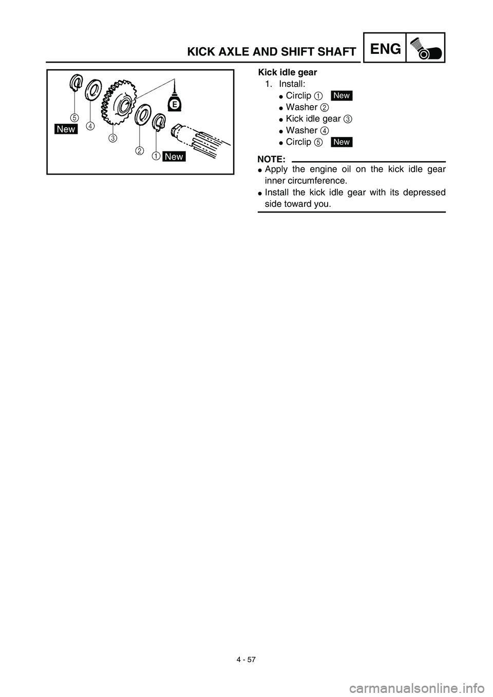
Kick idle gear
1. Install:
�Circlip 1
�Washer 2
�Kick idle gear 3
�Washer 4
�Circlip 5
NOTE:
�Apply the engine oil on the kick idle gear
inner circumference.
�Install the kick idle gear with its depressed
side toward you.
New
New
Page 364 of 578

4 - 60
ENGCDI MAGNETO AND STARTER CLUTCH
3. Check:
�Starter clutch operation
�Install the starter clutch drive gear 1 onto
the starter clutch 2 and hold the starter
clutch.
�When turning the starter clutch drive gear
counterclockwise ı, the starter clutch and
the starter clutch drive gear should
engage. If the starter clutch drive gear and
starter clutch do not engage, the starter
clutch is faulty and must be replaced.
�When turning the starter clutch drive gear
clockwise Å, it should turn freely.
If the starter clutch drive gear does not
turn freely, the starter clutch is faulty and
must be replaced.
Å
ı
1
2
EC4L5000
ASSEMBLY AND INSTALLATION
CDI magneto
1. Install:
�Stator 1
�Bolt (stator)
�Lead guide
�Screw (lead guide) 2
�Pickup coil 3
�Bolt (pickup coil)
2. Install:
�Stater idle gear 1
�Plate 2
�Bolt 3
�Washer 4
NOTE:
Apply the engine oil on the starter idle gear
inner circumference.
T R..10 Nm (1.0 m · kg, 7.2 ft · lb)LT
T R..7 Nm (0.7 m · kg, 5.1 ft · lb)LT
T R..10 Nm (1.0 m · kg, 7.2 ft · lb)LT
4
1
2
3
ET R..7 Nm (0.7 m · kg, 5.1 ft · lb)
Page 366 of 578

4 - 61
ENG
3. Install the starter clutch
1
on the rotor
2
.
NOTE:
�
Install the starter clutch with its plate portion
a
facing the rotor.
�
Insert the plate portion of the starter clutch
so that it is flush with the surface of contact
b
with the rotor.
12 b
a
4. Tighten:
�
Bolt (starter clutch)
NOTE:
Caulk
a
the end of the starter clutch holding
bolt near its outer diameter to serve as a stop-
per.
a
T R..30 Nm (3.0 m · kg, 22 ft · lb)
5. Install:
�
Starter wheel gear
1
�
Woodruff key
2
�
Rotor
3
NOTE:
�
Clean the tapered portion of the crankshaft
and the magneto hub.
�
When installing the magneto rotor, make
sure the woodruff key is properly seated in
the key way of the crankshaft.
�
Apply the engine oil on the starter wheel
gear inner circumference.
6. Tighten:
�
Nut (magneto)
1
NOTE:
Tighten the nut (magneto)
1
while holding the
magneto
2
with a sheave holder
3
.
Sheave holder:
YS-1880-A/90890-01701
2
1
3
E
T R..80 Nm (8.0 m · kg, 58 ft · lb)
CDI MAGNETO AND STARTER CLUTCH
Page 370 of 578
4 - 63
ENG
ENGINE REMOVAL
ENGINE REMOVAL
Extent of removal:
1
Engine removal
Extent of removal Order Part name Q’ty Remarks
ENGINE REMOVAL
Preparation for removal Hold the machine by placing the
suitable stand under the frame.
Seat, fuel tank and side covers Refer to “SEAT, FUEL TANK AND SIDE
COVERS” section.
Carburetor Refer to “CARBURETOR” section.
Muffler Refer to “MUFFLER” section.
Clutch cable Disconnect at engine side.
Spark plug cap
Disconnect the CDI magneto
lead.
Disconnect the neutral switch
lead.
Starter motor Refer to “ELECTRIC STARTING SYS-
TEM” section in the CHAPTER 6.
Drain the engine oil. Refer to “ENGINE OIL REPLACEMENT”
section in the CHAPTER 3.
Page 402 of 578
4 - 79
ENGTRANSMISSION, SHIFT CAM AND SHIFT FORK
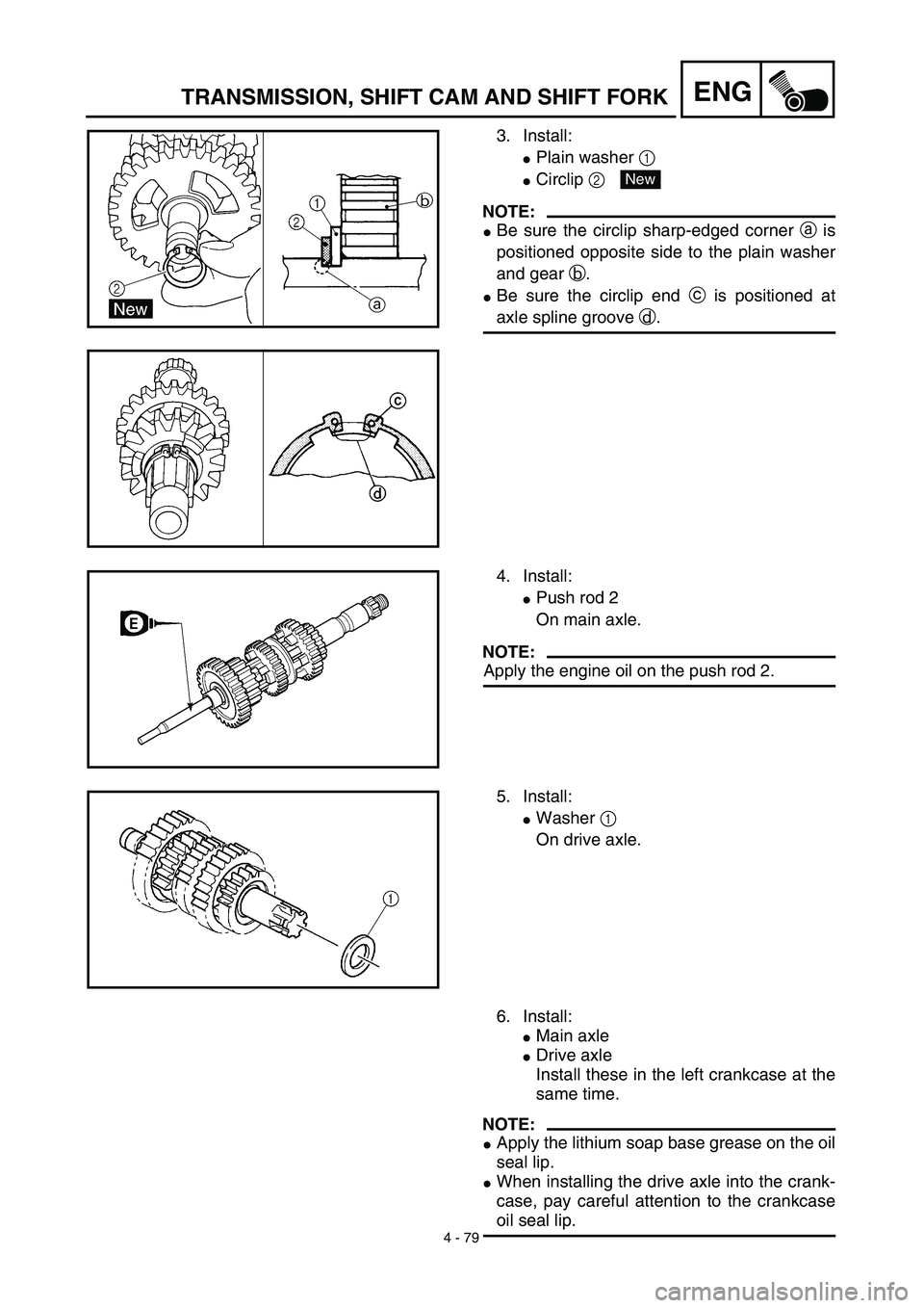
3. Install:
�Plain washer 1
�Circlip 2
NOTE:
�Be sure the circlip sharp-edged corner a is
positioned opposite side to the plain washer
and gear b.
�Be sure the circlip end c is positioned at
axle spline groove d.
New
4. Install:
�Push rod 2
On main axle.
NOTE:
Apply the engine oil on the push rod 2.
5. Install:
�Washer 1
On drive axle.
6. Install:
�Main axle
�Drive axle
Install these in the left crankcase at the
same time.
NOTE:
�Apply the lithium soap base grease on the oil
seal lip.
�When installing the drive axle into the crank-
case, pay careful attention to the crankcase
oil seal lip.
Page 404 of 578
4 - 80
ENGTRANSMISSION, SHIFT CAM AND SHIFT FORK
Shift cam and shift fork
1. Install:
�Shift fork 1 (L) 1
�Shift fork 2 (C) 2
�Shift fork 3 (R) 3
NOTE:
�Mesh the shift fork #1 (L) with the 2nd wheel
gear and #3 (R) with the 4th wheel gear on
the drive axle.
�Mesh the shift fork #2 (C) with the 3rd pinion
gear on the main axle.
2. Install:
�Shift cam 1
NOTE:
Apply the engine oil on the shift cam.
3. Install:
�Shift fork guide bar 1 (short) 1
�Shift fork guide bar 2 (long) 2
NOTE:
�Apply the engine oil on the guide bars.
�Be sure the long bar is inserted into the shift
forks #1 and #3 and the short one into #2.
4. Check:
�Shifter operation
�Transmission operation
Unsmooth operation → Repair.
Page 406 of 578
5 - 1
CHAS
FRONT WHEEL AND FRONT BRAKE (TT-R125E)
EC500000
CHASSIS
FRONT WHEEL AND FRONT BRAKE (TT-R125E)
Extent of removal:
1
Front wheel removal
2
Wheel bearing removal
3
Brake shoe plate assembly removal and disassembly
Extent of removal Order Part name Q’ty Remarks
Preparation for removal
FRONT WHEEL AND DRUM
BRAKE
Hold the machine by placing the
suitable stand under the engine.
WARNING
Support the machine securely so there is no
danger of it falling over.
1 Brake cable holder 1
2 Brake cable 1 Disconnect at the lever side, first.
3 Axle nut 1
4 Wheel axle 1
5 Front wheel 1
6 Collar set 1
7 Brake shoe plate assembly 1
8 Oil seal 1
9 Wheel bearing 2 Refer to “REMOVAL POINTS”.
10Spacer
1
2
3
1


EC500000
CHASSIS
FRONT WHEEL AND FRONT BRAKE (TT-R125E)
Extent of removal:
1
Front wheel removal
2
Wheel bearing removal
3
Brak")