Page 166 of 578

3 - 3
INSP
ADJ
PRE-OPERATION INSPECTION AND MAINTENANCE
PRE-OPERATION INSPECTION AND MAINTENANCE
Before riding for break-in operation or practice, make sure the machine is in good operating condi-
tion.
Before using this machine, check the following points.
GENERAL INSPECTION AND MAINTENANCE
Item Routine Page
FuelCheck that a fresh gasoline is filled in the fuel tank. Check the
fuel line for leakage.P.1-12
Engine oilCheck that the oil level is correct. Check the crankcase for leak-
age.P.3-7 ~ 10
Gear shifter and clutchCheck that gears can be shifted correctly in order and that the
clutch operates smoothly.P.3-4
Throttle grip/housingCheck that the throttle grip operation and free play are correctly
adjusted. Lubricate the throttle grip and housing, if necessary.P.3-4 ~ 5
BrakesCheck the play of front and rear brake and effect of front and
rear brake.
Check fluid level and leakage. (TT-R125LWE only)P.3-15 ~ 20
Drive chainCheck chain slack and alignment. Check that the chain is lubri-
cated properly.P.3-21 ~ 22
WheelsCheck for excessive wear and tire pressure. Check for loose
spokes and have no excessive play.P.3-27 ~ 28
SteeringCheck that the handlebar can be turned smoothly and have no
excessive play.P.3-28 ~ 30
Front forks and rear shock
absorber assemblyCheck that they operate smoothly and there is no oil leakage. P.3-23 ~ 26
Cables (wires)Check that the clutch and throttle cables move smoothly. Check
that they are not caught when the handlebars are turned or
when the front forks travel up and down.—
Muffler Check that the muffler is tightly mounted and has no cracks. P.4-2
Sprocket Check that the driven sprocket tightening nut is not loose. P.3-20
Lubrication Check for smooth operation. Lubricate if necessary. P.3-31
Bolts and nuts Check the chassis and engine for loose bolts and nuts. —
Lead connectorsCheck that the CDI magneto, CDI unit, and ignition coil are con-
nected tightly.P.1-5
Page 176 of 578
3 - 7
INSP
ADJ
ENGINE OIL LEVEL INSPECTION
6. Apply:
�Foam-air-filter oil or engine mixing oil
To the element.
NOTE:
Squeeze out the excess oil. Element should be
wet but not dripping.
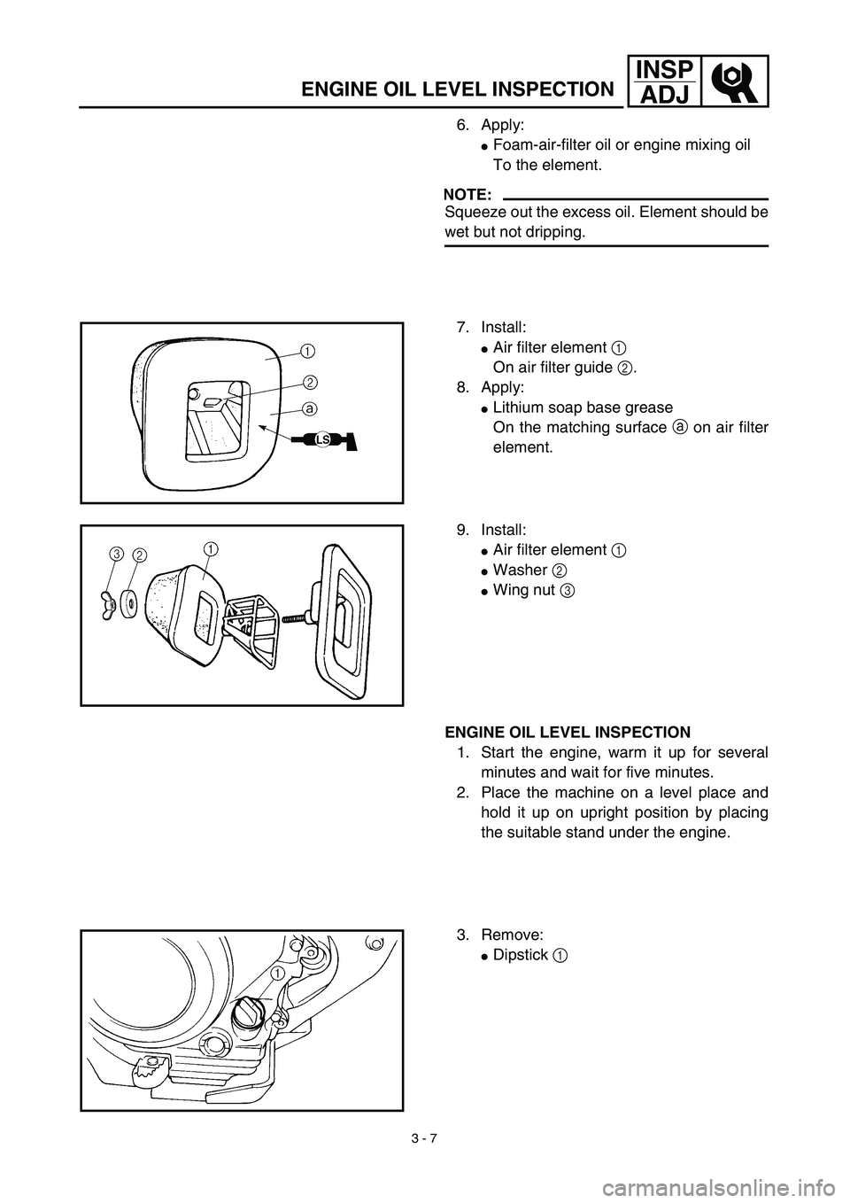
7. Install:
�Air filter element 1
On air filter guide 2.
8. Apply:
�Lithium soap base grease
On the matching surface a on air filter
element.
9. Install:
�Air filter element 1
�Washer 2
�Wing nut 3
ENGINE OIL LEVEL INSPECTION
1. Start the engine, warm it up for several
minutes and wait for five minutes.
2. Place the machine on a level place and
hold it up on upright position by placing
the suitable stand under the engine.
3. Remove:
�Dipstick 1
Page 178 of 578

3 - 8
INSP
ADJ
ENGINE OIL LEVEL INSPECTION
4. Check:
�Oil level
Oil level should be between maximum
a and minimum b marks.
Oil level is low → Add oil to proper
level.
NOTE:
When inspecting the oil level, do not screw the
dipstick into the oil tank. Insert the gauge
lightly.
(For USA and CDN)
CAUTION:
�Do not add any chemical additives.
Engine oil also lubricates the clutch and
additives could cause clutch slippage.
�Do not allow foreign material to enter the
crankcase.
Recommended oil:
At –10 ˚C (10 ˚F) or higher Å:
Yamalube 4 (10W-30) or SAE
10W-30 type SE motor oil
At 5 ˚C (40 ˚F) or higher ı:
Yamalube 4 (20W-40) or SAE
20W-40 type SE motor oil
(Except for USA and CDN)
CAUTION:
�Do not add any chemical additives or use
oils with a grade of CD a or higher.
�Do not use oils labeled “ENERGY CON-
SERVING II” b or higher. Engine oil also
lubricates the clutch and additives could
cause clutch slippage.
�Do not allow foreign materials to enter the
crankcase.
Recommended oil:
Refer to the following chart for
selection of oils which are suited
to the atmospheric temperatures.
Recommended engine oil classi-
fication:
API STANDARD:
API “SE” or higher grade
(Designed primarily for motor-
cycles)
Page 180 of 578
3 - 9
INSP
ADJ
ENGINE OIL REPLACEMENT
5. Install:
�Dipstick
6. Start the engine and let it warm up for
several minutes.
7. Turn off the engine and inspect the oil
level once again.
NOTE:
Wait a few minutes until the oil settles before
inspecting the oil level.
ENGINE OIL REPLACEMENT
1. Start the engine and warm it up for sev-
eral minutes and wait for five minute.
2. Place the machine on a level place and
hold it on upright position by placing the
suitable stand under the engine.
3. Place a suitable container under the
engine.
4. Remove:
�Oil drain bolt 1
�Dipstick 2
Drain the engine oil.
5. Install:
�Copper washer
�Oil drain bolt 1
New
T R..20 Nm (2.0 m · kg, 14 ft · lb)
6. Fill:
�Engine oil
7. Check:
�Oil leakage
8. Check:
�Engine oil level
9. Install:
�Dipstick 2
Oil capacity:
Periodic oil change:
1.0 L (0.88 Imp qt, 1.06 US qt)
Page 182 of 578

3 - 10
INSP
ADJOIL PRESSURE INSPECTION/PILOT AIR SCREW
ADJUSTMENT/ENGINE IDLING SPEED ADJUSTMENT
OIL PRESSURE INSPECTION
1. Check:
�Oil pressure
Checking steps:
�Slightly loosen the oil pressure check bolt
1.
�Start the engine and keep it idling until oil
starts to seep from the oil pressure check
bolt. If no oil comes out after one minute,
turn the engine off so it will not seize.
�Check oil passages and oil pump for dam-
age or leakage.
�Start the engine after solving the prob-
lem(s) and recheck the oil pressure.
�Tighten the oil pressure check bolt.
T R..
Oil pressure check bolt:
7 Nm (0.7 m • kg, 5.1 ft • lb)
PILOT AIR SCREW ADJUSTMENT
1. Adjust:
�Pilot air screw 1
Adjustment steps:
NOTE:
To optimize the fuel flow at a smaller throttle
opening, each machine’s pilot air screw has
been individually set at the factory. Before
adjusting the pilot air screw, turn it in fully
and count the number of turns. Record this
number as the factory-set number of turns
out.
�Screw in the pilot air screw until it is lightly
seated.
�Back out by the specified number of turns.
Pilot air screw:
2-1/2 ~ 3-1/2 turns out (example)
ENGINE IDLING SPEED ADJUSTMENT
1. Start the engine and thoroughly warm it
up.
2. Attach:
�Inductive tachometer
To spark plug lead.
3. Adjust:
�Engine idling speed
Page 206 of 578

3 - 22
INSP
ADJ
DRIVE CHAIN SLACK ADJUSTMENT
6. Lubricate:
�Drive chain
Drive chain lubricant:
SAE 10W-30 motor oil or suit-
able chain lubricants
DRIVE CHAIN SLACK ADJUSTMENT
1. Elevate the rear wheel by placing the
suitable stand under the engine.
2. Check:
�Drive chain slack a
In the center between the drive axle
and rear wheel axle.
Out of specification → Adjust.
NOTE:
Before checking and/or adjusting, rotate the
rear wheel through several revolutions and
check the slack several times to find the tight-
est point. Check and/or adjust chain slack with
rear wheel in this “tight chain” position.
Drive chain slack:
35 ~ 50 mm (1.4 ~ 2.0 in)
3. Adjust:
�Drive chain slack
Drive chain slack adjustment steps:
�Loosen the axle nut 1.
�Turn both drive chain pullers 2 the same
amount a and adjust them to the stopper
in the same position so that the drive chain
slack is within the specified limits.
CAUTION:
Too small chain slack will overload the
engine and other vital parts; keep the
slack within the specified limits.
�Tighten the axle nut while pushing down
the drive chain.
T R..
Axle nut:
60 Nm (6.0 m • kg, 43 ft • lb)
Page 210 of 578

3 - 24
INSP
ADJ
REAR SHOCK ABSORBER ASSEMBLY
INSPECTION
1. Inspect:
�Swingarm smooth action
Abnormal noise/unsmooth action →
Grease the pivoting points or repair the
pivoting points.
Damage/oil leakage → Replace.
REAR SHOCK ABSORBER SPRING
PRELOAD ADJUSTMENT
1. Elevate the rear wheel by placing the
suitable stand under the engine.
2. Remove:
�Left side cover
3. Loosen:
�Locknut 1
4. Adjust:
�Spring preload
By turning the adjuster 2.
NOTE:
�Be sure to remove all dirt and mud from
around the locknut and adjuster before
adjustment.
�The length of the spring (installed) changes
1.5 mm (0.06 in) per turn of the adjuster.
CAUTION:
Never attempt to turn the adjuster beyond
the maximum or minimum setting.Stiffer →Increase the spring preload.
(Turn the adjuster 2 in.)
Softer →Decrease the spring preload.
(Turn the adjuster 2 out.)
Spring length (installed) a:
Standard length Extent of adjustment
TT-R125E:
165 mm
(6.50 in)
TT-R125LWE:
160.5 mm
(6.32 in)TT-R125E:
155 ~ 175 mm
(6.10 ~ 6.89 in)
TT-R125LWE:
147.5 ~ 167.5 mm
(5.81 ~ 6.59 in)
REAR SHOCK ABSORBER ASSEMBLY INSPECTION/
REAR SHOCK ABSORBER SPRING PRELOAD ADJUSTMENT
Page 276 of 578
4 - 16
ENGCYLINDER HEAD
Warpage limit:
0.03 mm (0.0012 in)
�If the warpage is out of specification,
resurface the cylinder head.
�Place #400 ~ 600 grit wet sandpaper on
the surface plate, and re-surface the head
using a figure-eight sanding pattern.
NOTE:
Rotate the cylinder head several times to
avoid removing too much material from one
side.
ASSEMBLY AND INSTALLATION
Cylinder head
1. Install:
�Dowel pin 1
�Gasket 2 New
2. Install:
�Cylinder head
�Copper washer
�Bolt (cylinder head)
NOTE:
�Apply Quick gasket® (YAMAHA Bond
No.1215) on end of the cylinder head bolts
(M6), as shown.
�Apply the engine oil on the contact surfaces of
the bolts (cylinder head) and copper washers.
�Follow the numerical order shown in the illus-
tration. Tighten the bolts in two stages.
Quick gasket®:
ACC-QUICK-GS-KT
YAMAHA Bond No.1215:
90890-85505
T R..M8 22 Nm (2.2 m · kg, 16 ft · lb)
M6 10 Nm (1.0 m · kg, 7.2 ft · lb)