Page 366 of 578

4 - 61
ENG
3. Install the starter clutch
1
on the rotor
2
.
NOTE:
�
Install the starter clutch with its plate portion
a
facing the rotor.
�
Insert the plate portion of the starter clutch
so that it is flush with the surface of contact
b
with the rotor.
12 b
a
4. Tighten:
�
Bolt (starter clutch)
NOTE:
Caulk
a
the end of the starter clutch holding
bolt near its outer diameter to serve as a stop-
per.
a
T R..30 Nm (3.0 m · kg, 22 ft · lb)
5. Install:
�
Starter wheel gear
1
�
Woodruff key
2
�
Rotor
3
NOTE:
�
Clean the tapered portion of the crankshaft
and the magneto hub.
�
When installing the magneto rotor, make
sure the woodruff key is properly seated in
the key way of the crankshaft.
�
Apply the engine oil on the starter wheel
gear inner circumference.
6. Tighten:
�
Nut (magneto)
1
NOTE:
Tighten the nut (magneto)
1
while holding the
magneto
2
with a sheave holder
3
.
Sheave holder:
YS-1880-A/90890-01701
2
1
3
E
T R..80 Nm (8.0 m · kg, 58 ft · lb)
CDI MAGNETO AND STARTER CLUTCH
Page 400 of 578
4 - 78
ENGTRANSMISSION, SHIFT CAM AND SHIFT FORK
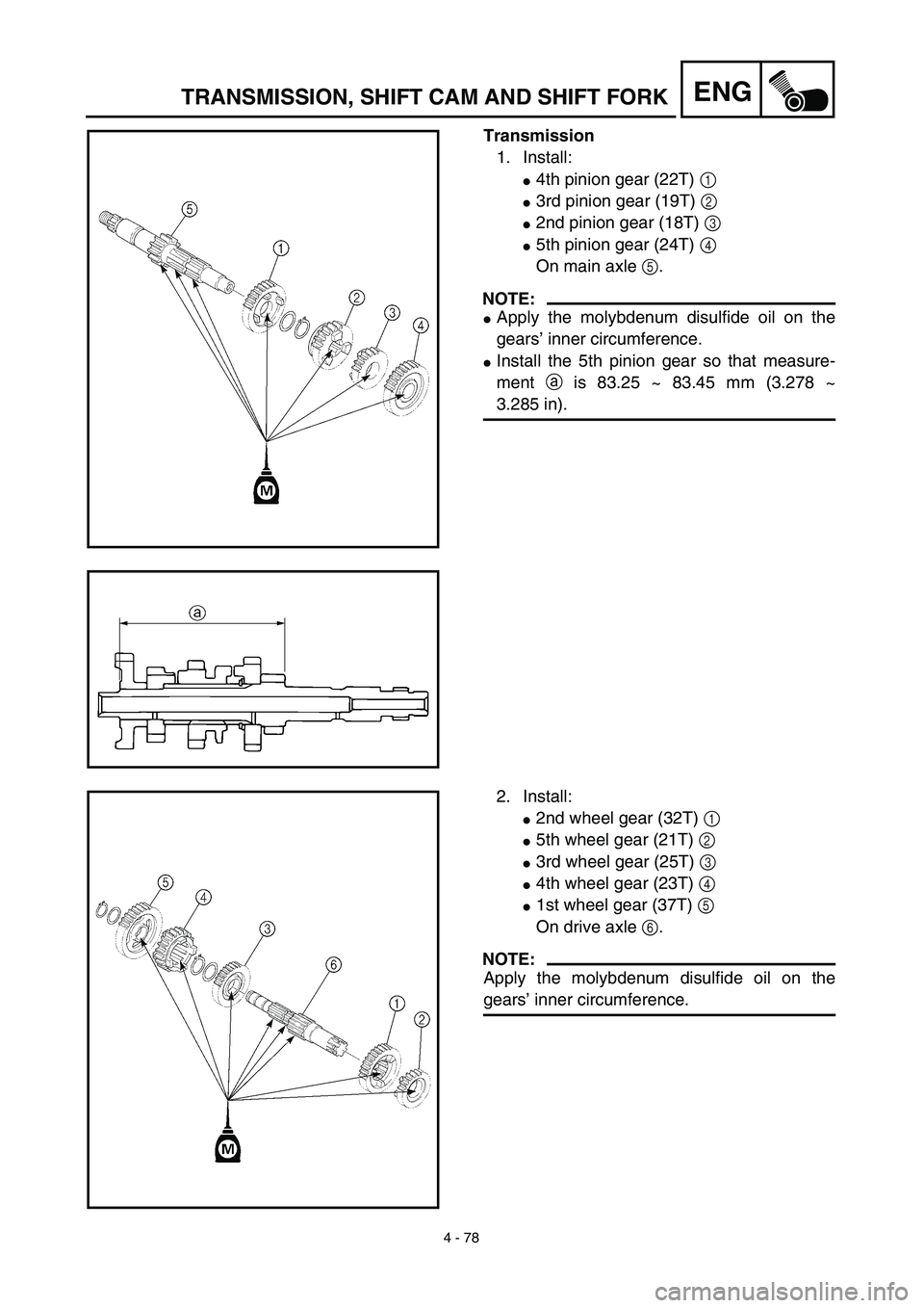
Transmission
1. Install:
�4th pinion gear (22T) 1
�3rd pinion gear (19T) 2
�2nd pinion gear (18T) 3
�5th pinion gear (24T) 4
On main axle 5.
NOTE:
�Apply the molybdenum disulfide oil on the
gears’ inner circumference.
�Install the 5th pinion gear so that measure-
ment a is 83.25 ~ 83.45 mm (3.278 ~
3.285 in).
2. Install:
�2nd wheel gear (32T) 1
�5th wheel gear (21T) 2
�3rd wheel gear (25T) 3
�4th wheel gear (23T) 4
�1st wheel gear (37T) 5
On drive axle 6.
NOTE:
Apply the molybdenum disulfide oil on the
gears’ inner circumference.
Page 404 of 578
4 - 80
ENGTRANSMISSION, SHIFT CAM AND SHIFT FORK
Shift cam and shift fork
1. Install:
�Shift fork 1 (L) 1
�Shift fork 2 (C) 2
�Shift fork 3 (R) 3
NOTE:
�Mesh the shift fork #1 (L) with the 2nd wheel
gear and #3 (R) with the 4th wheel gear on
the drive axle.
�Mesh the shift fork #2 (C) with the 3rd pinion
gear on the main axle.
2. Install:
�Shift cam 1
NOTE:
Apply the engine oil on the shift cam.
3. Install:
�Shift fork guide bar 1 (short) 1
�Shift fork guide bar 2 (long) 2
NOTE:
�Apply the engine oil on the guide bars.
�Be sure the long bar is inserted into the shift
forks #1 and #3 and the short one into #2.
4. Check:
�Shifter operation
�Transmission operation
Unsmooth operation → Repair.
Page 406 of 578
5 - 1
CHAS
FRONT WHEEL AND FRONT BRAKE (TT-R125E)
EC500000
CHASSIS
FRONT WHEEL AND FRONT BRAKE (TT-R125E)
Extent of removal:
1
Front wheel removal
2
Wheel bearing removal
3
Brake shoe plate assembly removal and disassembly
Extent of removal Order Part name Q’ty Remarks
Preparation for removal
FRONT WHEEL AND DRUM
BRAKE
Hold the machine by placing the
suitable stand under the engine.
WARNING
Support the machine securely so there is no
danger of it falling over.
1 Brake cable holder 1
2 Brake cable 1 Disconnect at the lever side, first.
3 Axle nut 1
4 Wheel axle 1
5 Front wheel 1
6 Collar set 1
7 Brake shoe plate assembly 1
8 Oil seal 1
9 Wheel bearing 2 Refer to “REMOVAL POINTS”.
10Spacer
1
2
3
1
Page 408 of 578
5 - 2
CHAS
FRONT WHEEL AND FRONT BRAKE (TT-R125E)
Extent of removal Order Part name Q’ty Remarks
11 Brake shoe 2
12 Spring 2
13 Brake camshaft lever 1
14 Wear indicator plate 1
15 Brake camshaft 1
16 Brake shoe plate 1
3
Page 410 of 578
5 - 3
CHAS
FRONT WHEEL AND FRONT BRAKE (TT-R125E)
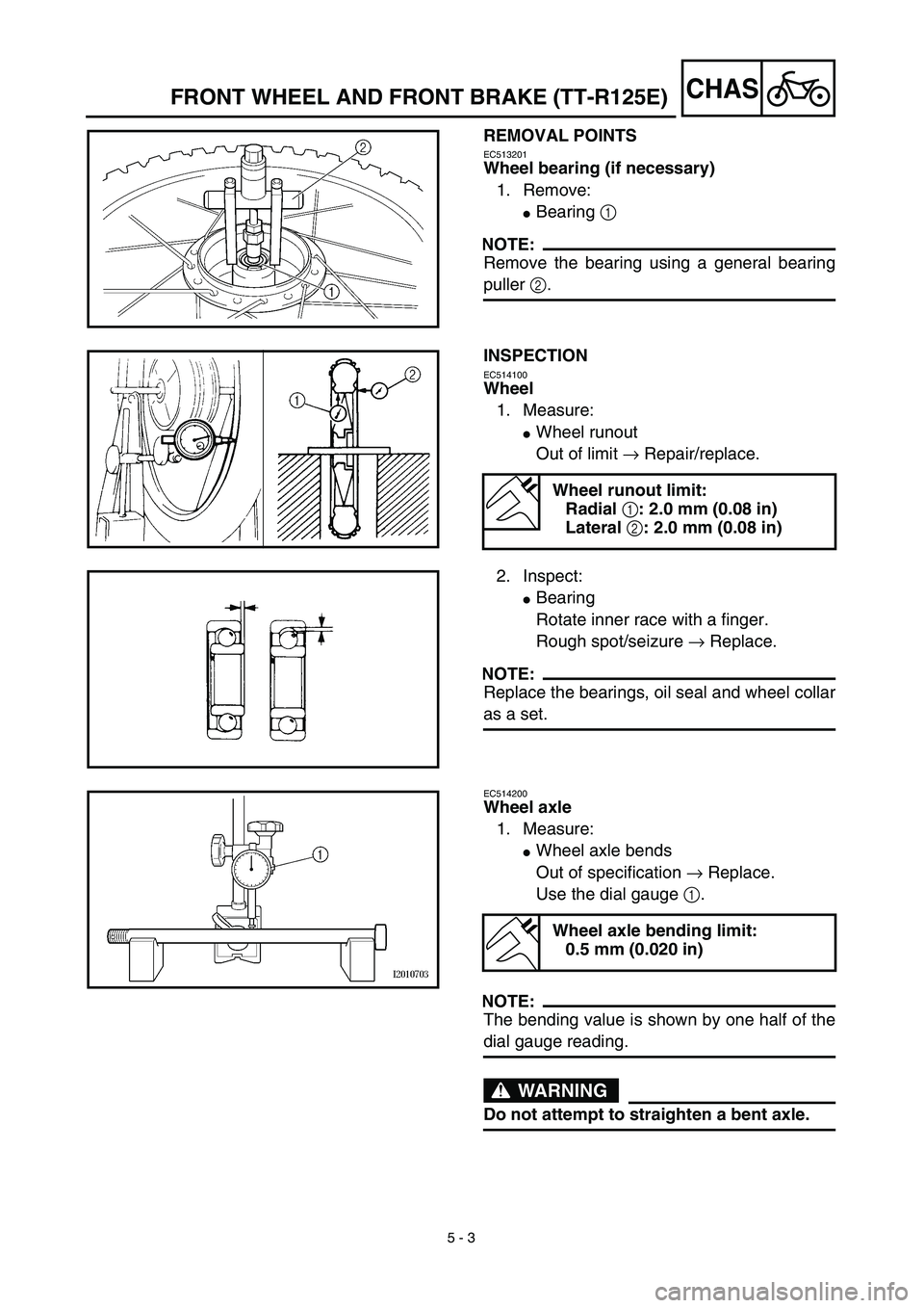
REMOVAL POINTS
EC513201
Wheel bearing (if necessary)
1. Remove:
�
Bearing
1
NOTE:
Remove the bearing using a general bearing
puller
2
.
INSPECTION
EC514100
Wheel
1. Measure:
�
Wheel runout
Out of limit
→
Repair/replace.
Wheel runout limit:
Radial
1
: 2.0 mm (0.08 in)
Lateral
2
: 2.0 mm (0.08 in)
2. Inspect:
�
Bearing
Rotate inner race with a finger.
Rough spot/seizure
→
Replace.
NOTE:
Replace the bearings, oil seal and wheel collar
as a set.
EC514200
Wheel axle
1. Measure:
�
Wheel axle bends
Out of specification
→
Replace.
Use the dial gauge
1
.
NOTE:
The bending value is shown by one half of the
dial gauge reading.
WARNING
Do not attempt to straighten a bent axle.
Wheel axle bending limit:
0.5 mm (0.020 in)
Page 412 of 578
5 - 4
CHAS
FRONT WHEEL AND FRONT BRAKE (TT-R125E)
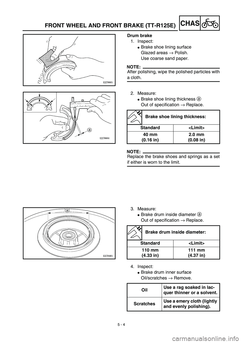
Drum brake
1. Inspect:
�
Brake shoe lining surface
Glazed areas
→
Polish.
Use coarse sand paper.
NOTE:
After polishing, wipe the polished particles with
a cloth.
2. Measure:
�
Brake shoe lining thickness
a
Out of specification
→
Replace.
NOTE:
Replace the brake shoes and springs as a set
if either is worn to the limit.
Brake shoe lining thickness:
Standard
40 mm
(0.16 in)2.0 mm
(0.08 in)
3. Measure:
�
Brake drum inside diameter
a
Out of specification
→
Replace.
Brake drum inside diameter:
Standard
110 mm
(4.33 in)111 mm
(4.37 in)
4. Inspect:
�
Brake drum inner surface
Oil/scratches
→
Remove.
OilUse a rag soaked in lac-
quer thinner or a solvent.
ScratchesUse a emery cloth (lightly
and evenly polishing).
Page 414 of 578
5 - 5
CHAS
FRONT WHEEL AND FRONT BRAKE (TT-R125E)
ASSEMBLY AND INSTALLATION
Brake shoe plate assembly
1. Install:
�
Brake camshaft
1
NOTE:
Apply the lithium soap base grease on the
brake camshaft.
2. Check:
�
Brake camshaft operation
Unsmooth operation
→
Repair.
3. Install:
�
Wear indicator plate
1
NOTE:
When installing the wear indicator plate to the
brake camshaft align the projection
a
on the
wear indicator plate with the slots
b
on the
brake camshaft.
4. Install:
�
Brake camshaft lever
1
NOTE:
Install the brake camshaft lever in relation to
the punch mark
a
as shown.
1
1a
T R..10 Nm (1.0 m · kg, 7.2 ft · lb)
5. Install:
�
Springs
1
�
Brake shoes 2
NOTE:
Apply the lithium soap base grease on the
pivot pin.
WARNING
Do not apply grease to the brake shoe lin-
ings.
New


EC500000
CHASSIS
FRONT WHEEL AND FRONT BRAKE (TT-R125E)
Extent of removal:
1
Front wheel removal
2
Wheel bearing removal
3
Brak")

Extent of removal Order Part name Q’ty Remarks
11 Brake shoe 2
12 Spring 2
13 Brake camshaft lever 1
14 Wear indicator plate 1
15 Brake camshaf")