Page 296 of 510
4 - 44
ENGCLUTCH AND PRIMARY DRIVEN GEAR
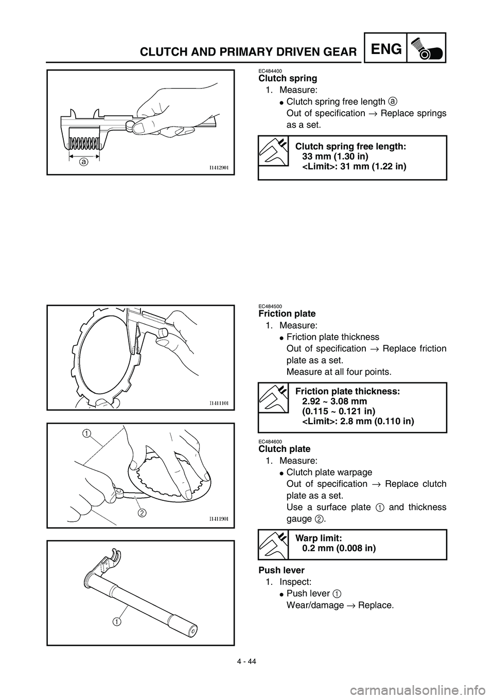
EC484400
Clutch spring
1. Measure:
�Clutch spring free length a
Out of specification → Replace springs
as a set.
Clutch spring free length:
33 mm (1.30 in)
: 31 mm (1.22 in)
EC484500
Friction plate
1. Measure:
�Friction plate thickness
Out of specification → Replace friction
plate as a set.
Measure at all four points.
EC484600
Clutch plate
1. Measure:
�Clutch plate warpage
Out of specification → Replace clutch
plate as a set.
Use a surface plate 1 and thickness
gauge 2.
Push lever
1. Inspect:
�Push lever 1
Wear/damage → Replace.
Friction plate thickness:
2.92 ~ 3.08 mm
(0.115 ~ 0.121 in)
: 2.8 mm (0.110 in)
Warp limit:
0.2 mm (0.008 in)
Page 298 of 510
4 - 45
ENGCLUTCH AND PRIMARY DRIVEN GEAR
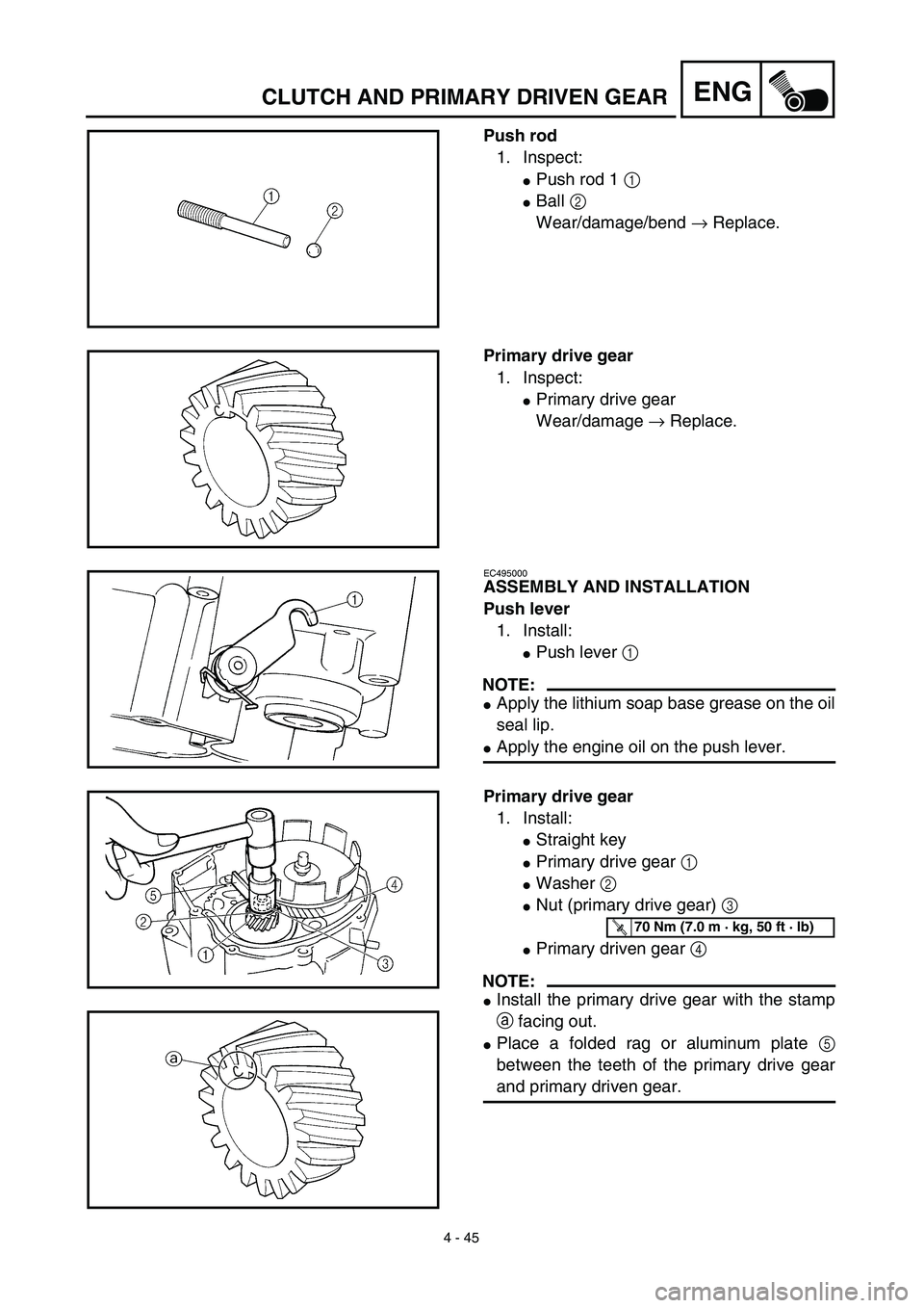
Push rod
1. Inspect:
�Push rod 1 1
�Ball 2
Wear/damage/bend → Replace.
Primary drive gear
1. Inspect:
�Primary drive gear
Wear/damage → Replace.
EC495000
ASSEMBLY AND INSTALLATION
Push lever
1. Install:
�Push lever 1
NOTE:
�Apply the lithium soap base grease on the oil
seal lip.
�Apply the engine oil on the push lever.
Primary drive gear
1. Install:
�Straight key
�Primary drive gear 1
�Washer 2
�Nut (primary drive gear) 3
�Primary driven gear 4
NOTE:
�Install the primary drive gear with the stamp
a facing out.
�Place a folded rag or aluminum plate 5
between the teeth of the primary drive gear
and primary driven gear.
T R..70 Nm (7.0 m · kg, 50 ft · lb)
Page 300 of 510
4 - 46
ENGCLUTCH AND PRIMARY DRIVEN GEAR
Clutch
1. Install:
�Conical spring washer 1
�Thrust plate 2
�Primary driven gear 3
�Thrust plate 4
�Clutch boss 5
2. Install:
�Lock washer
�Nut (clutch boss) 1
NOTE:
Use the clutch holding tool 2 to hold the clutch
boss.
ÅFor USA and CDN
ıExcept for USA and CDN
3. Bend:
�Lock washer tab
Clutch holding tool:
YM-91042/90890-04086
New
T R..60 Nm (6.0 m · kg, 43 ft · lb)
Å
ı
4. Install:
�Friction plate 1
�Clutch plate 2
NOTE:
�Install the clutch plates and friction plates
alternately on the clutch boss, starting with a
friction plate and ending with a friction plate.
�Apply the engine oil on the friction plates and
clutch plates.
�Be sure to install a clutch plate with projec-
tion a offset approximately 90˚ from previ-
ous plates projection. Continue this
procedure in a clockwise direction until all
clutch plates are installed.
Page 302 of 510
4 - 47
ENGCLUTCH AND PRIMARY DRIVEN GEAR
5. Install:
�Ball
NOTE:
Apply the engine oil on the ball.
6. Install:
�Push rod 1 1
�Push plate 2
�Washer 3
�Nut (push rod 1) 4
7. Install:
�Pressure plate 1
�Clutch spring 2
�Bolt (clutch spring) 3
NOTE:
�Align the arrow mark a on the pressure
plate with the punched mark b on the clutch
boss.
�Tighten the bolts in stage, using a crisscross
pattern.
T R..6 Nm (0.6 m · kg, 4.3 ft · lb)
8. Check:
�Push lever position
Push the push lever assembly in the
arrow direction and make sure that the
mach mark are aligned → adjust.
aMatch mark on the push lever assembly
bMatch mark on the crankcase
Page 304 of 510
4 - 48
ENGCLUTCH AND PRIMARY DRIVEN GEAR
9. Adjust:
�Push lever position
Adjustment steps:
�Loosen the locknut 1.
�Turn the push rod 1 2 clockwise or coun-
terclockwise to match alignment marks.
�Hold the push rod 1 to prevent it from
moving and tighten the locknut to specifi-
cation.
�Tighten the locknut 1.
T R..
Locknut:
8 Nm (0.8 m • kg, 5.8 ft • lb)
10. Install:
�Dowel pins
�Gasket (right crankcase cover)
�Right crankcase cover
�Bolts (right crankcase cover)
NOTE:
�Apply Quick gasket® (YAMAHA Bond
No.1215) to end of the right crankcase cover
bolts, as shown.
�Tighten the bolts in stages, using a criss-
cross pattern.
Quick gasket®:
ACC-QUICK-GS-KT
YAMAHA Bond No.1215:
90890-85505
New
T R..10 Nm (1.0 m · kg, 7.2 ft · lb)
11. Install:
�Kickstarter crank 1
�Nut (kickstarter crank) 2
NOTE:
Install the kickstarter crank so that there is 5 ~
10 mm (0.2 ~ 0.4 in) a between the kickstarter
crank and the right crankcase cover.
T R..50 Nm (5.0 m · kg, 36 ft · lb)
Page 306 of 510
4 - 49
ENGOIL PUMP
OIL PUMP
Extent of removal:1 Oil pump removal
Extent of removal Order Part name Q’ty Remarks
OIL PUMP REMOVAL
Preparation for removal Clutch and primary drive gear Refer to “CLUTCH AND PRIMARY
DRIVEN GEAR” section.
1 Rotary filter 1
2 Oil pump drive gear 1
3 Oil pump assembly 1
4 Gasket 1
5Oil strainer
1
1
Page 314 of 510
4 - 53
ENGKICK AXLE AND SHIFT SHAFT
KICK AXLE AND SHIFT SHAFT
KICK AXLE AND SHIFT SHAFT
Extent of removal:1 Kick axle removal2 Shift shaft removal
Extent of removal Order Part name Q’ty Remarks
KICK AXLE AND SHIFT SHAFT
REMOVAL
Preparation for removal Shift pedal link Refer to “ENGINE REMOVAL” section.
Clutch Refer to “CLUTCH AND PRIMARY
DRIVEN GEAR” section.
1 Kick axle assembly 1 Refer to “REMOVAL POINTS”.
2 Circlip 1
3 Washer 1
4 Kick idle gear 1
5 Washer 1
6 Circlip 1
7 Shift shaft 1
8 Circlip 1
9 Torsion spring 1
10 Bolt (stopper lever) 1
11 Stopper lever 1
12 Spring 1
13 Segment 1 Refer to “REMOVAL POINTS”.
1
2
Page 330 of 510
4 - 61
ENGENGINE REMOVAL
ENGINE REMOVAL
Extent of removal:1 Engine removal
Extent of removal Order Part name Q’ty Remarks
ENGINE REMOVAL
Preparation for removal Hold the machine by placing the
suitable stand under the frame.
Seat, fuel tank and side covers Refer to “SEAT, FUEL TANK AND SIDE
COVERS” section.
Carburetor Refer to “CARBURETOR” section.
Muffler Refer to “MUFFLER” section.
Clutch cable Disconnect at engine side.
Spark plug cap
Disconnect the CDI magneto
lead.
Drain the engine oil. Refer to “ENGINE OIL REPLACEMENT”
section in the CHAPTER 3.


 4 - 49
ENGOIL PUMP
OIL PUMP
Extent of removal:1 Oil pump removal
Extent of removal Order Part name Q’ty Remarks
OIL PUMP REMOVAL
Preparation for removal Clutch and primary drive gear Refer to “CL")
 4 - 53
ENGKICK AXLE AND SHIFT SHAFT
KICK AXLE AND SHIFT SHAFT
KICK AXLE AND SHIFT SHAFT
Extent of removal:1 Kick axle removal2 Shift shaft removal
Extent of removal Order Part name Q’ty Remarks
KICK")
 4 - 61
ENGENGINE REMOVAL
ENGINE REMOVAL
Extent of removal:1 Engine removal
Extent of removal Order Part name Q’ty Remarks
ENGINE REMOVAL
Preparation for removal Hold the machine by placing the
suita")