Page 350 of 510
4 - 71
ENGCRANKCASE, CRANKSHAFT AND BALANCER
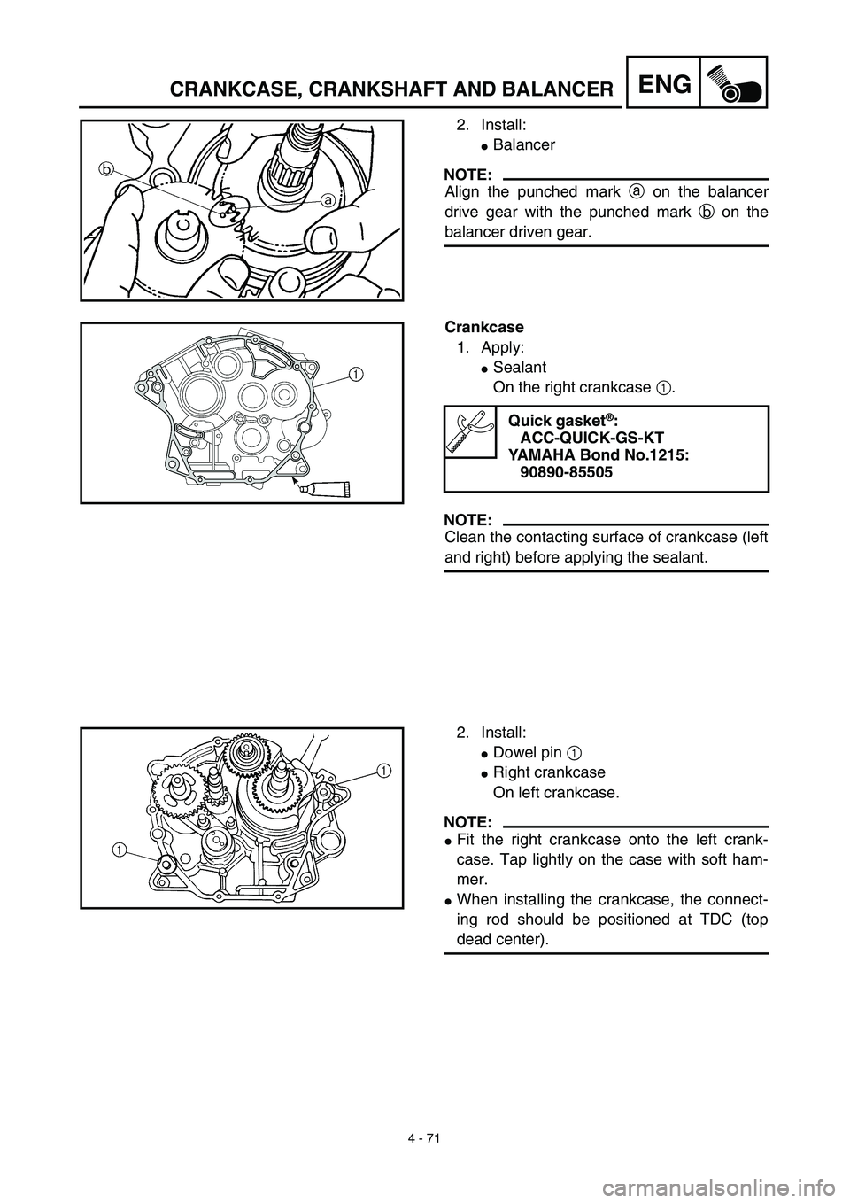
2. Install:
�Balancer
NOTE:
Align the punched mark a on the balancer
drive gear with the punched mark b on the
balancer driven gear.
Crankcase
1. Apply:
�Sealant
On the right crankcase 1.
NOTE:
Clean the contacting surface of crankcase (left
and right) before applying the sealant.
Quick gasket®:
ACC-QUICK-GS-KT
YAMAHA Bond No.1215:
90890-85505
2. Install:
�Dowel pin 1
�Right crankcase
On left crankcase.
NOTE:
�Fit the right crankcase onto the left crank-
case. Tap lightly on the case with soft ham-
mer.
�When installing the crankcase, the connect-
ing rod should be positioned at TDC (top
dead center).
Page 356 of 510
4 - 74
ENGTRANSMISSION, SHIFT CAM AND SHIFT FORK
REMOVAL POINTS
Transmission
1. Remove:
�Main axle 1
�Drive axle 2
NOTE:
�Tap lightly on the transmission drive axle
with a soft hammer to remove.
�Remove assembly carefully. Note the posi-
tion of each part. Pay particular attention to
the location and direction of shift forks.
EC4H4000
INSPECTION
EC4H4200
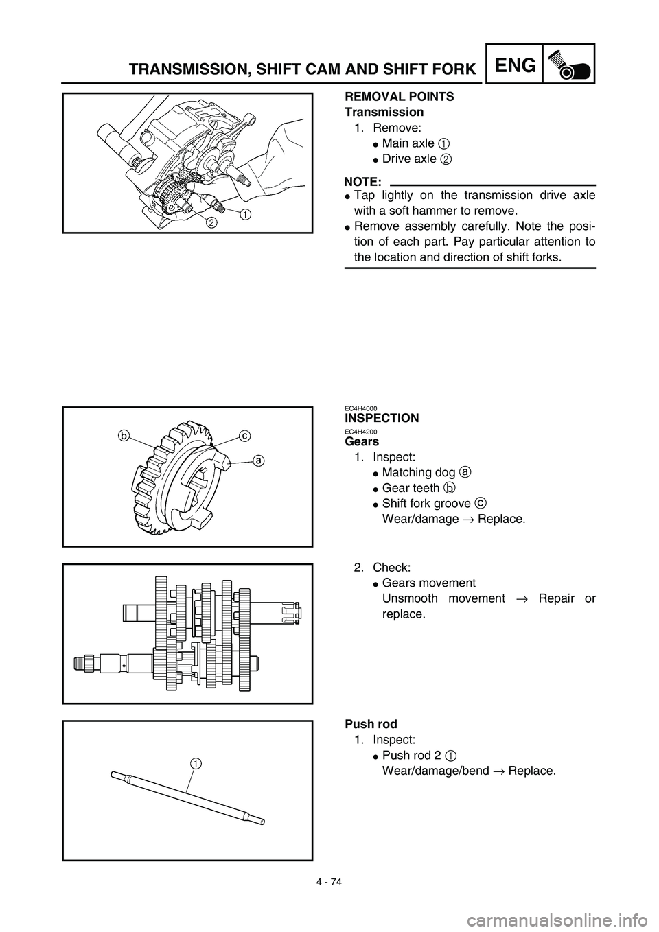
Gears
1. Inspect:
�Matching dog a
�Gear teeth b
�Shift fork groove c
Wear/damage → Replace.
2. Check:
�Gears movement
Unsmooth movement → Repair or
replace.
Push rod
1. Inspect:
�Push rod 2 1
Wear/damage/bend → Replace.
Page 372 of 510
5 - 4
CHAS
FRONT WHEEL AND FRONT BRAKE (TT-R125)
Drum brake
1. Inspect:
�
Brake shoe lining surface
Glazed areas
→
Polish.
Use coarse sand paper.
NOTE:
After polishing, wipe the polished particles with
a cloth.
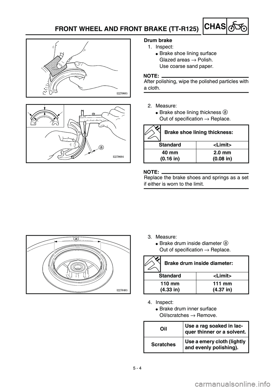
2. Measure:
�
Brake shoe lining thickness
a
Out of specification
→
Replace.
NOTE:
Replace the brake shoes and springs as a set
if either is worn to the limit.
Brake shoe lining thickness:
Standard
40 mm
(0.16 in)2.0 mm
(0.08 in)
3. Measure:
�
Brake drum inside diameter
a
Out of specification
→
Replace.
Brake drum inside diameter:
Standard
110 mm
(4.33 in)111 mm
(4.37 in)
4. Inspect:
�
Brake drum inner surface
Oil/scratches
→
Remove.
OilUse a rag soaked in lac-
quer thinner or a solvent.
ScratchesUse a emery cloth (lightly
and evenly polishing).
Page 404 of 510
 5 - 20
CHAS
Brake master cylinder
1. Install:
�Brake master cylinder 1
�Brake master cylinder bracket 2
�Bolt (brake master cylinder bracket) 3
NOTE:
�Install the brake master cylinder bracket so
t")
5 - 20
CHAS
Brake master cylinder
1. Install:
�Brake master cylinder 1
�Brake master cylinder bracket 2
�Bolt (brake master cylinder bracket) 3
NOTE:
�Install the brake master cylinder bracket so
that the arrow mark a face upward.
�First tighten the bolts on the upper side of the
brake master cylinder bracket, and then
tighten the bolts on the lower side.
2. Install:
�Brake lever 1
�Spring 2
�Bolt (brake lever) 3
�Nut (brake lever) 4
NOTE:
�Apply the lithium soap base grease on the
bolt and brake lever sliding surface.
�Apply the molybdenum disulfide grease on
the tip of the adjuster bolt.
T R..9 Nm (0.9 m · kg, 6.5 ft · lb)
T R..7 Nm (0.7 m · kg, 5.1 ft · lb)
T R..7 Nm (0.7 m · kg, 5.1 ft · lb)
Brake hose
1. Install:
�Copper washer 1
�Brake hose 2
�Union bolt 3
WARNING
Always use new copper washers.
CAUTION:
Install the brake hose so that its pipe por-
tion a directs as show and lightly touches
the projection b on the brake caliper.
New
T R..26 Nm (2.6 m · kg, 19 ft · lb)
FRONT BRAKE (TT-R125LW)
Page 420 of 510
5 - 28
CHASREAR WHEEL AND REAR BRAKE
4. Inspect:
�Brake drum inner surface.
Oil/scratches → Remove.
OilUse a rag soaked in lac-
quer thinner or a solvent.
ScratchesUse a emery cloth (lightly
and evenly polishing).
ASSEMBLY AND INSTALLATION
Brake shoe plate assembly
1. Install:
�Brake camshaft 1
NOTE:
Apply the lithium soap base grease on the
brake camshaft.
2. Check:
�Brake camshaft operation
Unsmooth operation → Repair.
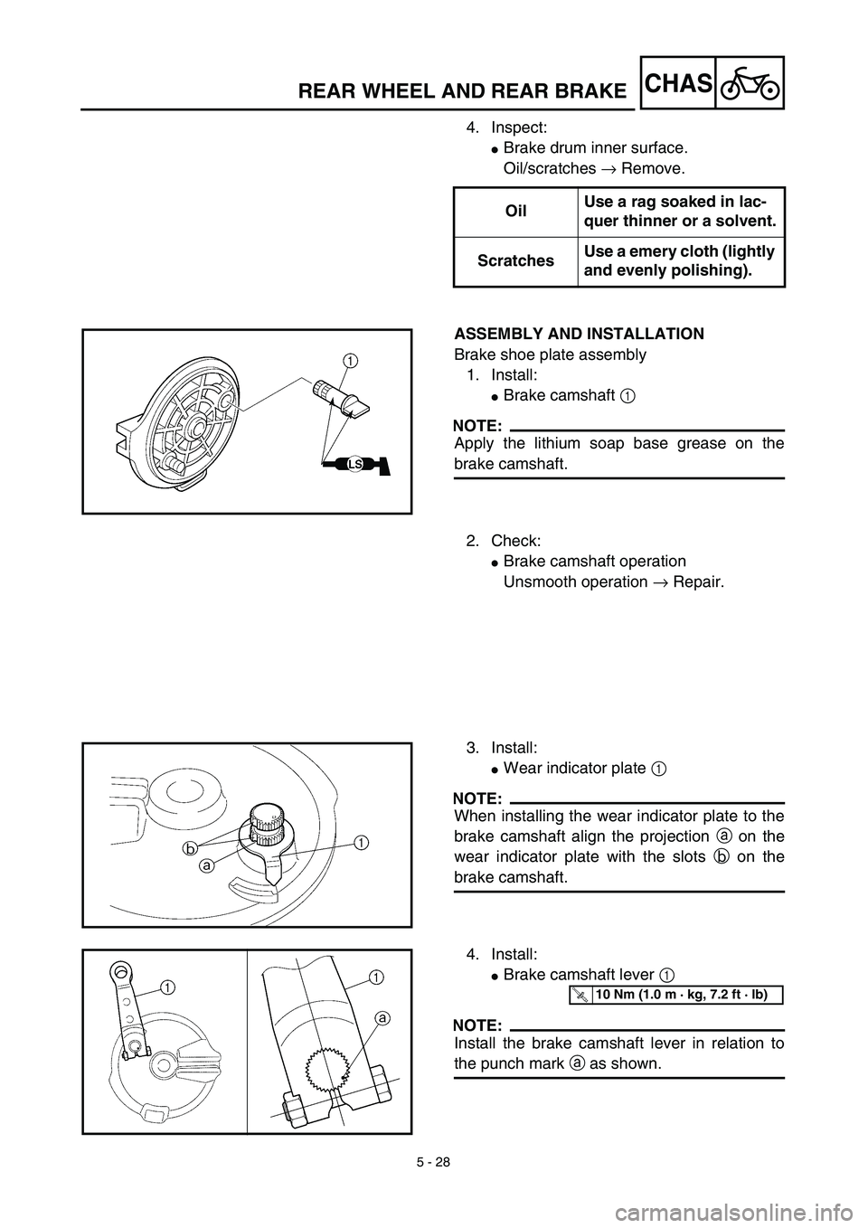
3. Install:
�Wear indicator plate 1
NOTE:
When installing the wear indicator plate to the
brake camshaft align the projection a on the
wear indicator plate with the slots b on the
brake camshaft.
4. Install:
�Brake camshaft lever 1
NOTE:
Install the brake camshaft lever in relation to
the punch mark a as shown.
T R..10 Nm (1.0 m · kg, 7.2 ft · lb)
Page:
< prev 1-8 9-16 17-24