Page 178 of 510
3 - 14
INSP
ADJ
SPARK ARRESTER CLEANING (For USA)
SPARK ARRESTER CLEANING (For USA)
WARNING
�Be sure the exhaust pipe and muffler are
cool before cleaning the spark arrester.
�Do not start the engine when cleaning the
exhaust system.
1. Remove:
�Bolt (spark arrester) 1
2. Remove:
�Spark arrester 1
Pull the spark arrester out of the muf-
fler.
3. Clean:
�Spark arrester
Tap the spark arrester lightly, then use
a wire brush to remove any carbon
deposits.
4. Install:
�Spark arrester
Insert the spark arrester into the muffler
and align the bolt holes.
�Bolt (spark arrester)
T R..10 Nm (1.0 m · kg, 7.2 ft · lb)
Page 206 of 510
3 - 28
INSP
ADJ
LUBRICATION
LUBRICATION
To ensure smooth operation of all compo-
nents, lubricate your machine during setup,
after break-in, and after every ride.
1All control cable
2Brake and clutch lever pivots
3Shift pedal pivot
4Footrest pivot
5Throttle-to-handlebar contact
6Drive chain
7Tube guide cable winding portion
8Throttle cable end
9Brake and clutch cable ends
(Clutch cable end only for the TT-R125LW)ÅUse Yamaha cable lube or equivalent on these
areas.
ıUse SAE 10W-30 motor oil or suitable chain
lubricants.
ÇLubricate the following areas with high quality,
lightweight lithium-soap base grease.
AAA
AAB
CC
Page 208 of 510
3 - 29
INSP
ADJ
ELECTRICAL/SPARK PLUG INSPECTION
EC370000
ELECTRICAL
EC371001
SPARK PLUG INSPECTION
1. Remove:
�Spark plug
2. Inspect:
�Electrode 1
Wear/damage → Replace.
�Insulator color 2
Normal condition is a medium to light
tan color.
Distinctly different color → Check the
engine condition.
NOTE:
When the engine runs for many hours at low
speeds, the spark plug insulator will become
sooty, even if the engine and carburetor are in
good operating condition.
3. Measure:
�Plug gap a
Use a wire gauge or thickness gauge.
Out of specification → Regap.
4. Clean the plug with a spark plug cleaner
if necessary.
Spark plug gap:
0.6 ~ 0.7 mm (0.02 ~ 0.03 in)
Standard spark plug:
CR7HSA (NGK)
U22FSR-U (DENSO)
5. Tighten:
�Spark plug
NOTE:
�Before installing a spark plug, clean the gas-
ket surface and plug surface.
�Finger-tighten a the spark plug before
torquing to specification b.
T R..13 Nm (1.3 m · kg, 9.4 ft · lb)
Page 224 of 510
4 - 8
ENGCARBURETOR
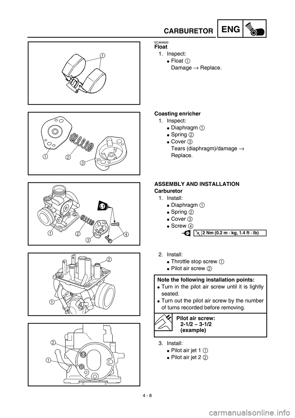
EC464600
Float
1. Inspect:
�Float 1
Damage → Replace.
Coasting enricher
1. Inspect:
�Diaphragm 1
�Spring 2
�Cover 3
Tears (diaphragm)/damage →
Replace.
ASSEMBLY AND INSTALLATION
Carburetor
1. Install:
�Diaphragm 1
�Spring 2
�Cover 3
�Screw 4
T R..2 Nm (0.2 m · kg, 1.4 ft · lb)LT
2. Install:
�Throttle stop screw 1
�Pilot air screw 2
3. Install:
�Pilot air jet 1 1
�Pilot air jet 2 2 Note the following installation points:
�Turn in the pilot air screw until it is lightly
seated.
�Turn out the pilot air screw by the number
of turns recorded before removing.
Pilot air screw:
2-1/2 ~ 3-1/2
(example)
Page 244 of 510
4 - 18
ENGCYLINDER HEAD
5. Install:
�Timing chain tensioner
6. Turn:
�Crankshaft
Counterclockwise several turns
7. Check:
�Rotor “I” mark
Align with the crankcase stationary
pointer.
�Camshaft match mark
Align with the cylinder head stationary
pointer.
Out of alignment → Adjust. Installation steps:
�While pressing the tensioner rod lightly
with fingers, use a thin screwdriver and
wind the tensioner rod up fully clockwise.
�With the rod fully wound, install the gasket
1 and the chain tensioner 2, and tighten
the bolts 3 to the specified torque.
T R..
Bolt (chain tensioner):
10 Nm (1.0 m • kg, 7.2 ft • lb)
�Release the screwdriver, check the ten-
sioner rod to come out and tighten the
gasket 4 and the cap bolt 5 to the speci-
fied torque.
T R..
Cap bolt (timing chain tensioner):
8 Nm (0.8 m • kg, 5.8 ft • lb)
8. Tighten:
�Bolt 1
NOTE:
Tighten the bolt while holding the rotor nut with
a wrench.
T R..20 Nm (2.0 m · kg, 14 ft · lb)
Page 266 of 510
 4 - 29
ENGVALVES AND VALVE SPRINGS
�Install the valve into the cylinder head.
�Turn the valve until the valve face and
valve seat are evenly polished, then clean
off all of the compound.
NOTE:
For bes")
4 - 29
ENGVALVES AND VALVE SPRINGS
�Install the valve into the cylinder head.
�Turn the valve until the valve face and
valve seat are evenly polished, then clean
off all of the compound.
NOTE:
For best lapping results, lightly tap the valve
seat while rotating the valve back and forth
between your hands.
�Apply a fine lapping compound to the
valve face and repeat the above steps.
NOTE:
After every lapping operation be sure to
clean off all of the compound from the valve
face and valve seat.
�Apply Mechanic’s blueing dye (Dykem) to
the valve face.
�Install the valve into the cylinder head.
�Press the valve through the valve guide
and onto the valve seat to make a clear
pattern.
�Measure the valve seat width again. If the
valve seat width is out of specification,
reface and re-lap the valve seat.
Valve spring
1. Measure:
�Valve spring free length a
Out of specification → Replace.
Free length (valve spring):
Intake:
32.55 mm (1.28 in)
: 31.2 mm (1.23 in)
Exhaust:
32.55 mm (1.28 in)
: 31.2 mm (1.23 in)
Page 270 of 510
4 - 31
ENGVALVES AND VALVE SPRINGS
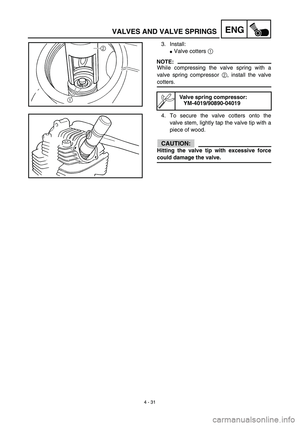
3. Install:
�Valve cotters 1
NOTE:
While compressing the valve spring with a
valve spring compressor 2, install the valve
cotters.
Valve spring compressor:
YM-4019/90890-04019
4. To secure the valve cotters onto the
valve stem, lightly tap the valve tip with a
piece of wood.
CAUTION:
Hitting the valve tip with excessive force
could damage the valve.
Page 342 of 510
 4 - 67
ENGCRANKCASE, CRANKSHAFT AND BALANCER
REMOVAL POINTS
Crankcase
1. Remove:
�Bolt (crankcase)
�Lead guide 1
�Clutch cable holder 2
NOTE:
Loosen each bolt 1/4 of a turn at a time and
after all t")
4 - 67
ENGCRANKCASE, CRANKSHAFT AND BALANCER
REMOVAL POINTS
Crankcase
1. Remove:
�Bolt (crankcase)
�Lead guide 1
�Clutch cable holder 2
NOTE:
Loosen each bolt 1/4 of a turn at a time and
after all the bolts are loosened, remove them.
2. Remove:
�Right crankcase 1
Use the crankcase separating tool 2.
NOTE:
�Fully tighten the tool holding bolts, but make
sure the tool body is parallel with the case. If
necessary, one screw may be backed out
slightly to level tool body.
�As pressure is applied, alternately tap on the
front engine mounting boss and transmission
shafts.
CAUTION:
Use soft hammer to tap on the case half.
Tap only on reinforced portions of case. Do
not tap on gasket mating surface. Work
slowly and carefully. Make sure the case
halves separate evenly. If one end “hangs
up”, take pressure off the push screw, re-
align, and start over. If the cases do not
separate, check for a remaining case screw
or fitting. Do not force.
Crankcase separating tool:
YU-1135-A/90890-01135

 3 - 28
INSP
ADJ
LUBRICATION
LUBRICATION
To ensure smooth operation of all compo-
nents, lubricate your machine during setup,
after break-in, and after every ride.
1All control cable
2Brake and clutch")