Page 192 of 510
3 - 21
INSP
ADJ
DRIVE CHAIN INSPECTION
EC369002
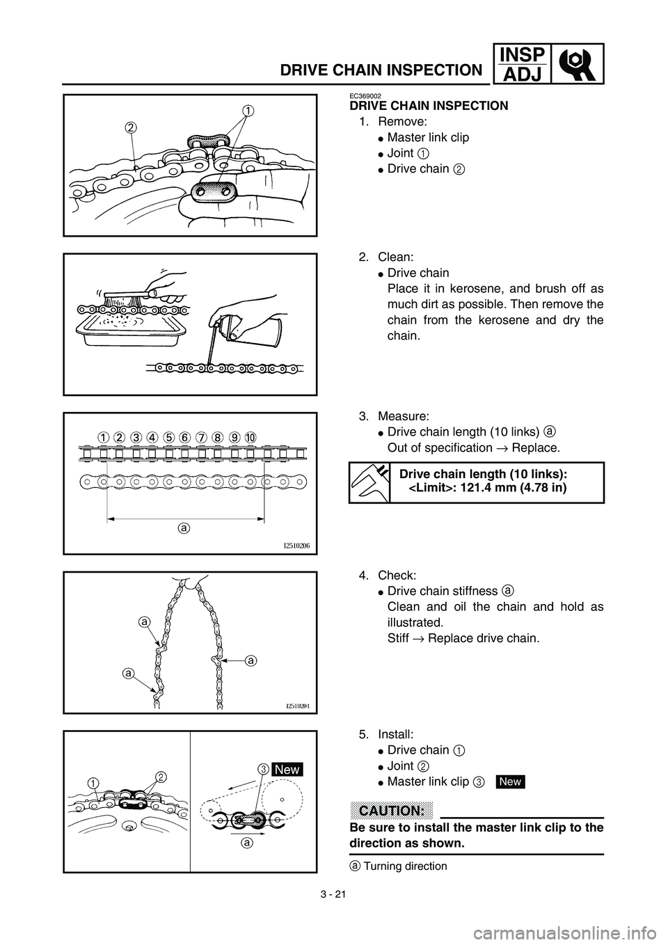
DRIVE CHAIN INSPECTION
1. Remove:
�Master link clip
�Joint 1
�Drive chain 2
2. Clean:
�Drive chain
Place it in kerosene, and brush off as
much dirt as possible. Then remove the
chain from the kerosene and dry the
chain.
3. Measure:
�Drive chain length (10 links) a
Out of specification → Replace.
Drive chain length (10 links):
: 121.4 mm (4.78 in)
4. Check:
�Drive chain stiffness a
Clean and oil the chain and hold as
illustrated.
Stiff → Replace drive chain.
5. Install:
�Drive chain 1
�Joint 2
�Master link clip 3
CAUTION:
Be sure to install the master link clip to the
direction as shown.
aTurning direction
New
Page 194 of 510
 3 - 22
INSP
ADJ
DRIVE CHAIN SLACK ADJUSTMENT
6. Lubricate:
�Drive chain
Drive chain lubricant:
SAE 10W-30 motor oil or suit-
able chain lubricants
DRIVE CHAIN SLACK ADJUSTMENT
1. Elevate the rear whee")
3 - 22
INSP
ADJ
DRIVE CHAIN SLACK ADJUSTMENT
6. Lubricate:
�Drive chain
Drive chain lubricant:
SAE 10W-30 motor oil or suit-
able chain lubricants
DRIVE CHAIN SLACK ADJUSTMENT
1. Elevate the rear wheel by placing the
suitable stand under the engine.
2. Check:
�Drive chain slack a
In the center between the drive axle
and rear wheel axle.
Out of specification → Adjust.
NOTE:
Before checking and/or adjusting, rotate the
rear wheel through several revolutions and
check the slack several times to find the tight-
est point. Check and/or adjust chain slack with
rear wheel in this “tight chain” position.
Drive chain slack:
35 ~ 50 mm (1.4 ~ 2.0 in)
3. Adjust:
�Drive chain slack
Drive chain slack adjustment steps:
�Loosen the axle nut 1.
�Turn both drive chain pullers 2 the same
amount a and adjust them to the stopper
in the same position so that the drive
chain slack is within the specified limits.
CAUTION:
Too small chain slack will overload the
engine and other vital parts; keep the
slack within the specified limits.
�Tighten the axle nut while pushing down
the drive chain.
T R..
Axle nut:
60 Nm (6.0 m • kg, 43 ft • lb)
Page 246 of 510
4 - 19
ENGCYLINDER HEAD
9. Check:
�Valve clearance
Out of specification → Adjust.
Refer to “VALVE CLEARANCE
INSPECTION AND ADJUSTMENT”
section in the CHAPTER 3.
10. Apply:
�Engine oil
On camshaft.
11. Install:
�Tappet cover 1
�Cylinder head side cover 2
T R..18 Nm (1.8 m · kg, 13 ft · lb)
T R..10 Nm (1.0 m · kg, 7.2 ft · lb)
12. Install:
�Timing mark accessing screw 1
�Crankshaft end accessing screw 2
T R..7 Nm (0.7 m · kg, 5.1 ft · lb)
T R..7 Nm (0.7 m · kg, 5.1 ft · lb)
13. Install:
�Spark plug
�Engine bracket
T R..13 Nm (1.3 m · kg, 9.4 ft · lb)
T R..40 Nm (4.0 m · kg, 29 ft · lb)
Page 302 of 510
4 - 47
ENGCLUTCH AND PRIMARY DRIVEN GEAR
5. Install:
�Ball
NOTE:
Apply the engine oil on the ball.
6. Install:
�Push rod 1 1
�Push plate 2
�Washer 3
�Nut (push rod 1) 4
7. Install:
�Pressure plate 1
�Clutch spring 2
�Bolt (clutch spring) 3
NOTE:
�Align the arrow mark a on the pressure
plate with the punched mark b on the clutch
boss.
�Tighten the bolts in stage, using a crisscross
pattern.
T R..6 Nm (0.6 m · kg, 4.3 ft · lb)
8. Check:
�Push lever position
Push the push lever assembly in the
arrow direction and make sure that the
mach mark are aligned → adjust.
aMatch mark on the push lever assembly
bMatch mark on the crankcase
Page 364 of 510
4 - 78
ENGTRANSMISSION, SHIFT CAM AND SHIFT FORK
Shift cam and shift fork
1. Install:
�Shift fork 1 (L) 1
�Shift fork 2 (C) 2
�Shift fork 3 (R) 3
NOTE:
�Mesh the shift fork #1 (L) with the 2nd wheel
gear and #3 (R) with the 4th wheel gear on
the drive axle.
�Mesh the shift fork #2 (C) with the 3rd pinion
gear on the main axle.
2. Install:
�Shift cam 1
NOTE:
Apply the engine oil on the shift cam.
3. Install:
�Shift fork guide bar 1 (short) 1
�Shift fork guide bar 2 (long) 2
NOTE:
�Apply the engine oil on the guide bars.
�Be sure the long bar is inserted into the shift
forks #1 and #3 and the short one into #2.
4. Check:
�Shifter operation
�Transmission operation
Unsmooth operation → Repair.
Page 420 of 510
5 - 28
CHASREAR WHEEL AND REAR BRAKE
4. Inspect:
�Brake drum inner surface.
Oil/scratches → Remove.
OilUse a rag soaked in lac-
quer thinner or a solvent.
ScratchesUse a emery cloth (lightly
and evenly polishing).
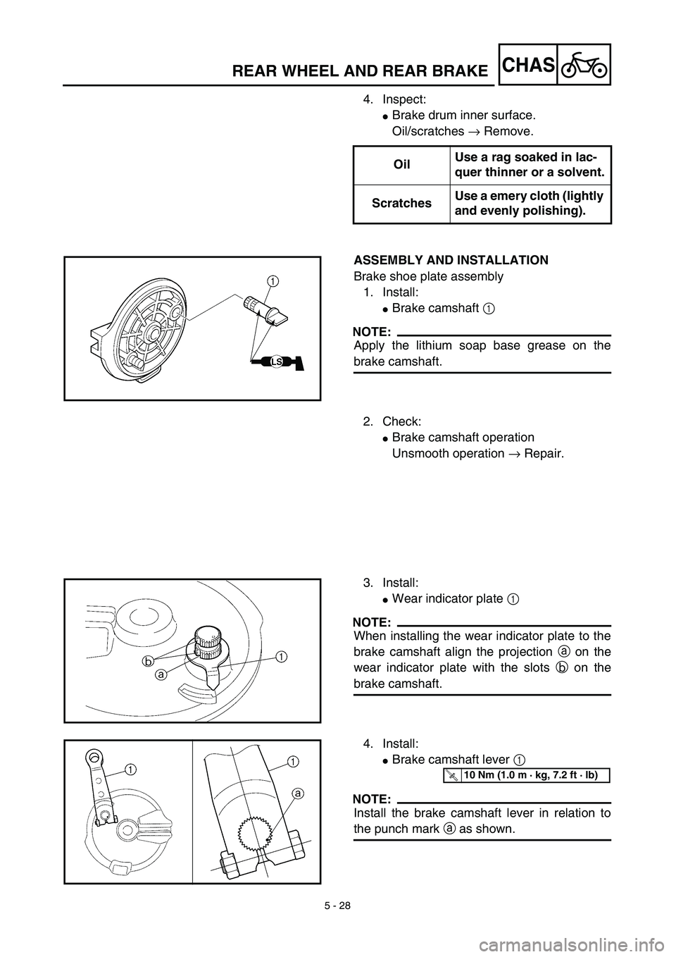
ASSEMBLY AND INSTALLATION
Brake shoe plate assembly
1. Install:
�Brake camshaft 1
NOTE:
Apply the lithium soap base grease on the
brake camshaft.
2. Check:
�Brake camshaft operation
Unsmooth operation → Repair.
3. Install:
�Wear indicator plate 1
NOTE:
When installing the wear indicator plate to the
brake camshaft align the projection a on the
wear indicator plate with the slots b on the
brake camshaft.
4. Install:
�Brake camshaft lever 1
NOTE:
Install the brake camshaft lever in relation to
the punch mark a as shown.
T R..10 Nm (1.0 m · kg, 7.2 ft · lb)
Page 440 of 510
5 - 38
CHASFRONT FORK
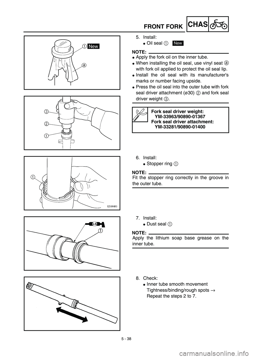
5. Install:
�Oil seal 1
NOTE:
�Apply the fork oil on the inner tube.
�When installing the oil seal, use vinyl seat a
with fork oil applied to protect the oil seal lip.
�Install the oil seal with its manufacturer's
marks or number facing upside.
�Press the oil seal into the outer tube with fork
seal driver attachment (ø30) 2 and fork seal
driver weight 3.
Fork seal driver weight:
YM-33963/90890-01367
Fork seal driver attachment:
YM-33281/90890-01400
New
6. Install:
�Stopper ring 1
NOTE:
Fit the stopper ring correctly in the groove in
the outer tube.
7. Install:
�Dust seal 1
NOTE:
Apply the lithium soap base grease on the
inner tube.
8. Check:
�Inner tube smooth movement
Tightness/binding/rough spots →
Repeat the steps 2 to 7.
Page 458 of 510
5 - 47
CHAS
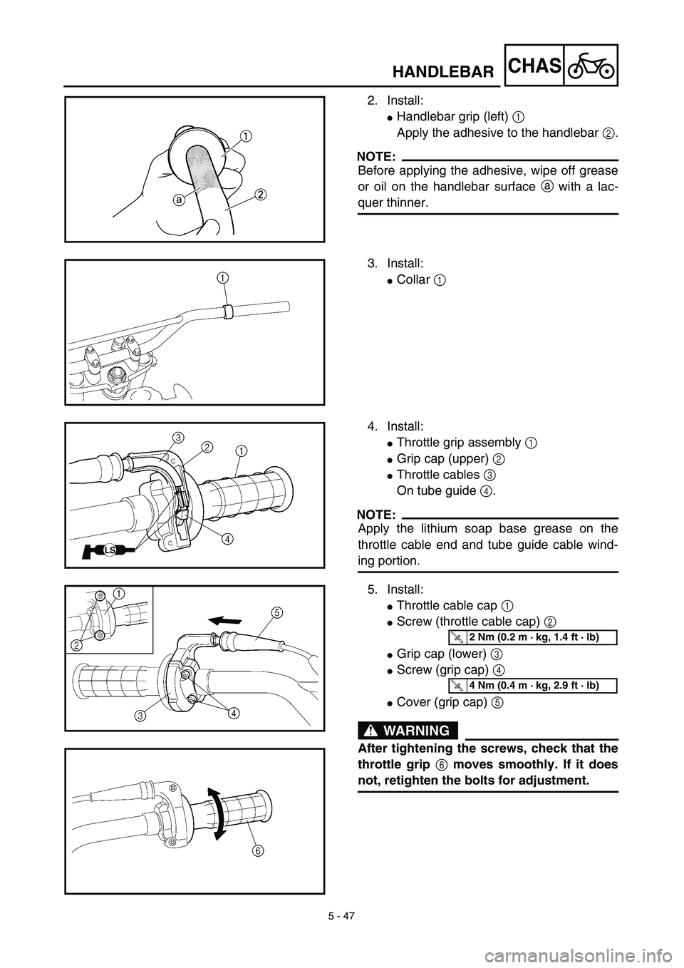
2. Install:
�Handlebar grip (left) 1
Apply the adhesive to the handlebar 2.
NOTE:
Before applying the adhesive, wipe off grease
or oil on the handlebar surface a with a lac-
quer thinner.
3. Install:
�Collar 1
4. Install:
�Throttle grip assembly 1
�Grip cap (upper) 2
�Throttle cables 3
On tube guide 4.
NOTE:
Apply the lithium soap base grease on the
throttle cable end and tube guide cable wind-
ing portion.
5. Install:
�Throttle cable cap 1
�Screw (throttle cable cap) 2
�Grip cap (lower) 3
�Screw (grip cap) 4
�Cover (grip cap) 5
WARNING
After tightening the screws, check that the
throttle grip 6 moves smoothly. If it does
not, retighten the bolts for adjustment.
T R..2 Nm (0.2 m · kg, 1.4 ft · lb)
T R..4 Nm (0.4 m · kg, 2.9 ft · lb)
HANDLEBAR