2003 YAMAHA TMAX battery
[x] Cancel search: batteryPage 15 of 104

2-2
DESCRIPTION
2
11. Battery, Fuses (page 6-32, 6-34)
12. Owner’s tool kit (page 6-1)
13. Front storage compartment (page 3-14)
14. Windshield
15. Air filter element (page 6-19)16. Radiator
17. Coolant level check window (page 6-17)
18. V-belt air filter element (right)
19. Centerstand (page 6-29)
20. Passenger footrest
1112131415
1817161920
Right view
5GJ-28199-E2 9/9/02 9:15 AM Page 13
Page 19 of 104

3-2
INSTRUMENT AND CONTROL FUNCTIONS
3
EAU03733.(Parking)
The steering is locked, and the tail-
light, license light and auxiliary light
are on, but all other electrical sys-
tems are off. The key can be
removed.
To turn the main switch to “
.”:
1. Turn the key to “LOCK”.
2. Slightly turn the key counter-
clockwise until it stops.
3. While still turning the key coun-
terclockwise, push it in until it
snaps into place.
ECA00043
cC
Do not use the parking position for
an extended length of time, other-
wise the battery may discharge.
If the engine oil is changed before the
oil change indicator light comes on
(i.e. before the periodic oil change
interval has been reached), the indi-
cator light must be reset after the oil
change for the next periodic oil
change to be indicated at the correct
time. (See page 6-15 for the resetting
procedure.)
The electrical circuit of the indicator
light can be checked according to the
following procedure.
1. Set the engine stop switch to “#”
and turn the key to “ON”.
2. Check that the indicator comes
on for a few seconds and then
goes off.
3. If the indicator light does not
come on, have a Yamaha dealer
check the electrical circuit.
EAU00056
Indicator lightsIndicator lights
EAU03797
Oil change indicator light “7”Oil change indicator light
This indicator light comes on at the
initial 1,000 km, then at 5,000 km and
every 5,000 km thereafter to indicate
that the engine oil should be
changed.
After changing the engine oil, reset
the oil change indicator light. (See
page 6-15 for the resetting proce-
dure.)
1234
1. Oil change indicator light “7”
2. V-belt replacement indicator light “V-BELT”
3. High beam indicator light “&”
4. Turn signal indicator lights “4” and “6”
5GJ-28199-E2 9/9/02 9:15 AM Page 17
Page 24 of 104

3-7
EAU03889
Turn signal switch “4/6”Turn signal switch
To signal a right-hand turn, push this
switch to “6”. To signal a left-hand
turn, push this switch to “4”. When
released, the switch returns to the
center position. To cancel the turn
signal lights, push the switch in after
it has returned to the center position.
EAU00129
Horn switch “*”Horn switch
Press this switch to sound the horn.
INSTRUMENT AND CONTROL FUNCTIONS
3
1
2
3
4
1. Pass switch “PASS”
2. Dimmer switch “&/%”
3. Turn signal switch “4/6”
4. Horn switch “*”
EAU03890
Engine stop switch “#/$”Engine stop switch
Set this switch to “#” before starting
the engine. Set this switch to “$” to
stop the engine in case of an emer-
gency, such as when the scooter
overturns or when the throttle cable is
stuck.
1
2
3
1. Engine stop switch “#/$”
2. Hazard switch “0”
3. Start switch “,”
EAU03826
Hazard switch “0”Hazard switch
With the key in the “ON” or “.” posi-
tion, use this switch to turn on the
hazard light (simultaneous flashing of
all turn signal lights).
The hazard light is used in case of an
emergency or to warn other drivers
when your scooter is stopped where
it might be a traffic hazard.
EC000006
cC
Do not use the hazard light for an
extended length of time, otherwise
the battery may discharge.
EAU03801
Start switch “,”Start switch
With the sidestand up, push this
switch while applying the front or rear
brake to crank the engine with the
starter.
EC000005
cC
See page 5-1 for starting instruc-
tions prior to starting the engine.
5GJ-28199-E2 9/9/02 9:15 AM Page 22
Page 31 of 104

3-14
INSTRUMENT AND CONTROL FUNCTIONS
3
EAU03805
Storage compartments
Storage compartments
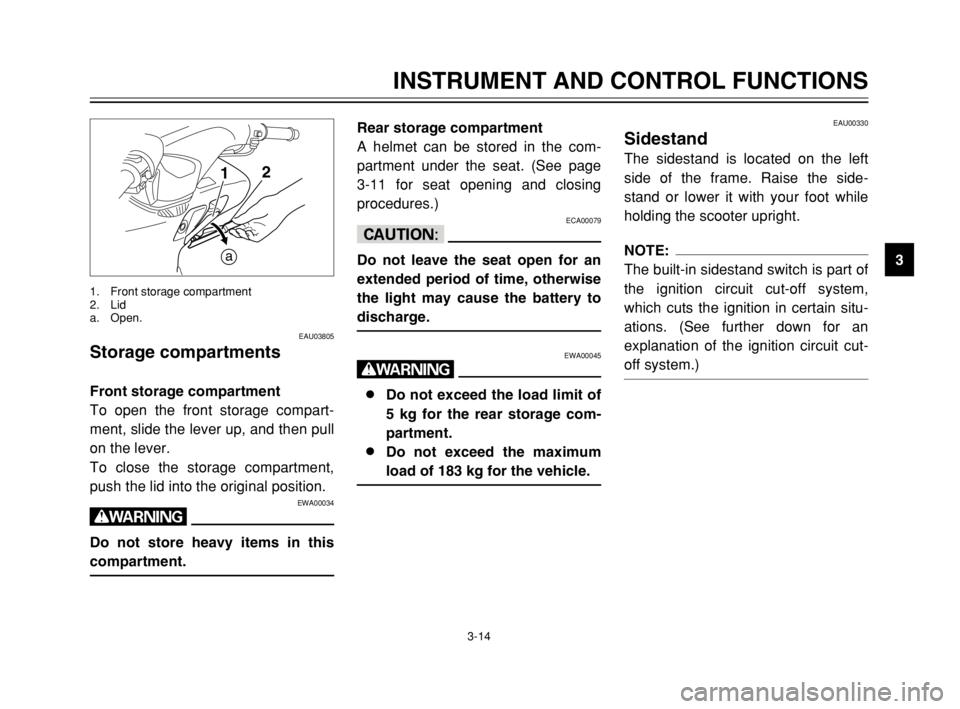
Front storage compartment
To open the front storage compart-
ment, slide the lever up, and then pull
on the lever.
To close the storage compartment,
push the lid into the original position.
EWA00034
w
Do not store heavy items in this
compartment.
1
a2
1. Front storage compartment
2. Lid
a. Open.
EAU00330
SidestandSidestand
The sidestand is located on the left
side of the frame. Raise the side-
stand or lower it with your foot while
holding the scooter upright.
NOTE:
The built-in sidestand switch is part of
the ignition circuit cut-off system,
which cuts the ignition in certain situ-
ations. (See further down for an
explanation of the ignition circuit cut-
off system.)
Rear storage compartment
A helmet can be stored in the com-
partment under the seat. (See page
3-11 for seat opening and closing
procedures.)
ECA00079
cC
Do not leave the seat open for an
extended period of time, otherwise
the light may cause the battery to
discharge.
EWA00045
w
8 8
Do not exceed the load limit of
5 kg for the rear storage com-
partment.
8 8
Do not exceed the maximum
load of 183 kg for the vehicle.
5GJ-28199-E2 9/9/02 9:15 AM Page 29
Page 40 of 104

5-1
EAU00372
OPERATION AND IMPORTANT RIDING POINTS
5
EAU03981
w
8 8
Become thoroughly familiar
with all operating controls and
their functions before riding.
Consult a Yamaha dealer
regarding any control or func-
tion that you do not thorough-
ly understand.
8 8
Never start the engine or oper-
ate it in a closed area for any
length of time. Exhaust fumes
are poisonous, and inhaling
them can cause loss of con-
sciousness and death within a
short time. Always make sure
that there is adequate ventila-
tion.
8 8
For safety, always start the
engine with the centerstand
down.
8 8
When the centerstand is down
and the engine is idling, keep
your hands and feet away from
the rear wheel.
EAU03843
Starting the engineStarting the engine
EC000046
cC
See page 5-4 for engine break-in
instructions prior to operating the
vehicle for the first time.
In order for the ignition circuit cut-off
system to enable starting, the side-
stand must be up.
EW000054
w
8 8
Before starting the engine,
check the function of the igni-
tion circuit cut-off system
according to the procedure
described on page 3-16.
8 8
Never ride with the sidestand
down.
1. Turn the key to “ON” and make
sure that the engine stop switch
is set to “#”.
2. Close the throttle completely.
3. Start the engine by pushing the
start switch while applying the
front or rear brake.
NOTE:
If the engine does not start, release
the start switch, wait a few seconds,
and then try again. Each starting
attempt should be as short as possi-
ble to preserve the battery. Do not
crank the engine more than
10 seconds on any one attempt. If
the engine does not start, try with the
throttle open 1/8 turn.
ECA00045
cC
For maximum engine life, never
accelerate hard when the engine is
cold!
5GJ-28199-E2 9/9/02 9:15 AM Page 38
Page 45 of 104

PERIODIC MAINTENANCE AND MINOR REPAIR
Owner’s tool kit ......................................................6-1
Periodic maintenance and lubrication chart ...........6-3
Removing and installing cowlings and panels .......6-6
Checking the spark plugs ......................................6-9
Engine oil and oil filter cartridge ...........................6-12
Chain drive oil ......................................................6-15
Coolant ................................................................6-17
Cleaning the air filter element ..............................6-19
Adjusting the carburetors .....................................6-21
Adjusting the engine idling speed ........................6-21
Adjusting the throttle cable free play ....................6-22
Adjusting the valve clearance ..............................6-22
Tires .....................................................................6-23
Cast wheels .........................................................6-25
Front and rear brake levers .................................6-25
Checking the front and rear brake pads ..............6-26
Checking the brake fluid level ..............................6-27
Changing the brake fluid ......................................6-28
Checking and lubricating the throttle grip
and cable ...........................................................6-29
Lubricating the front and rear brake levers ..........6-29
Checking and lubricating the centerstand and
sidestand ...........................................................6-29
Checking the front fork .........................................6-30Checking the steering ..........................................6-31
Checking the wheel bearings ...............................6-31
Battery .................................................................6-32
Replacing the fuses .............................................6-34
Replacing a headlight bulb ..................................6-35
Troubleshooting ...................................................6-36
Troubleshooting charts ........................................6-37
6
5GJ-28199-E2 9/9/02 9:15 AM Page 43
Page 54 of 104

6-9
PERIODIC MAINTENANCE AND MINOR REPAIR
6To install the cowling
1. Place the cowling in the original
position, and then install the
screws and bolts.
2. Install panels C and E.
EAU03816
Checking the spark plugsSpark plugs, checking
The spark plugs are important engine
components, which are easy to
check. Since heat and deposits will
cause any spark plug to slowly erode,
the spark plugs should be removed
and checked in accordance with the
periodic maintenance and lubrication
chart. In addition, the condition of the
spark plugs can reveal the condition
of the engine. Cowling C
To remove the cowling
1. Remove the cowling bolts.
2. Remove the battery cover by
removing the screws.
3. Pull the cowling off.
To install the cowling
1. Install the battery cover by
installing the screws.
2. Place the cowling in the original
position, and then install the
bolts.
1
2
1. Bolt (×2)
2. Screw (×3)
5GJ-28199-E2 9/9/02 9:15 AM Page 52
Page 77 of 104

6-32
PERIODIC MAINTENANCE AND MINOR REPAIR
6
EAU03876
BatteryBattery
This scooter is equipped with a
sealed-type (MF) battery, which does
not require any maintenance. There
is no need to check the electrolyte or
to add distilled water.
To charge the battery
Have a Yamaha dealer charge the
battery as soon as possible if it
seems to have discharged. Keep in
mind that the battery tends to dis-
charge more quickly if the scooter is
equipped with optional electrical
accessories.
1
1. Battery
To access the battery
1. Open the seat. (See page 3-11
for seat opening and closing pro-
cedures.)
2. Remove the battery cover by
removing the screws.
1
2
1. Screw (×3)
2. Battery cover
5GJ-28199-E2 9/9/02 9:15 AM Page 75