Page 84 of 134

3-27
E
CAUTION:@ Be sure to remove the clip from the
engine shut-off switch, otherwise the
engine will overheat and engine damage
may occur.
@
1. Shut the engine off by removing the clip
from the engine shut-off switch.
2. Swim to the rear of the watercraft. Climb
onto the right side of the capsized water-
craft and place both feet on the rub rail
near the stern.
NOTE:@ If the port (left) side of the capsized water-
craft is tilting upward, first tilt the watercraft
so the port (left) side is down by using your
weight to press down on the rub rail.
@
3. Grasp the ride plate with your left hand
and place your right hand under the
intake grate.
4. Lean backwards and forcefully pull the
watercraft clockwise until it is upright.
CAUTION:@ Do not turn the watercraft over counter-
clockwise, otherwise water may leak into
the carburetor and engine and cause
damage.
@
5. Start the engine, and then head for
shore to inspect the engine for water
damage.
CAUTION:@ If the watercraft has been capsized for
5 minutes or more, air may have entered
the oil injection system. Leave the engine
off, or operate only at trolling speed, for
10 minutes after the watercraft has been
turned right-side up. This will allow any
air to bleed off.
@
UGU572.book Page 27 Wednesday, August 28, 2002 1:31 PM
Page 93 of 134

E
4
EJU01086
MAINTENANCE AND
CARE
Storage ...................................................... 4-1
Flushing the cooling system .................. 4-1
Lubrication .............................................. 4-3
Fuel system ............................................ 4-4
Battery .................................................... 4-5
Cleaning the watercraft .......................... 4-6
Maintenance and adjustments .............. 4-7
Owner’s/Operator’s Manual and
tool kit ..................................................... 4-8
Periodic maintenance chart ................... 4-9
Inspecting the fuel system ................... 4-10
Inspecting the oil injection system ....... 4-12
Inspecting the jet thrust nozzle
angle ..................................................... 4-13
Inspecting the shift cable ..................... 4-13
Inspecting and adjusting the throttle
cable ..................................................... 4-13
Inspecting the QSTS mechanism ....... 4-14
Cleaning and adjusting the spark
plugs ..................................................... 4-15
Lubrication points ................................. 4-16
Adjusting the choke cable .................... 4-19
Inspecting the battery .......................... 4-20
Adjusting the carburetor ...................... 4-22
Replacing the fuse ............................... 4-23
Bleeding the oil injection pump ............ 4-23
Specifications ........................................ 4-24
UGU572.book Page 1 Wednesday, August 28, 2002 1:31 PM
Page 96 of 134

4-3
E
EJU01325
Lubrication
WARNING@ To reduce the risk of fire or explosion:
Never pour or spray gasoline, or any sub-
stance other than engine fogging oil
through the holes in the carburetor
silencer cover.
@
CAUTION:@ �Be sure to replace the caps securely
after fogging the engine. Otherwise
water could enter the engine and
cause damage.
�Do not attempt to run the engine at full
throttle or for more than 15 seconds
while the watercraft is out of the water,
otherwise the engine may overheat
and/or seize.
@
1. Open the silencer caps 1 on the
silencer.
2. Start the engine with the watercraft in a
well-ventilated area.
3. With the engine running at a fast idle,
quickly spray as much fogging oil as pos-
sible through the holes in the silencer
cover. Keep spraying until the engine
stalls (or a maximum of 15 seconds).
4. Install the caps securely.
5. Lubricate all cables such as the throttle,
choke, and steering cables.
NOTE:@ Use a suitable marine grease applicator to
pressure lubricate the cables and purge out
any moisture between the inner and outer
cables.
@
6. Lubricate the areas of the watercraft
specified under Lubrication points on
page 4-16.
UGU572.book Page 3 Wednesday, August 28, 2002 1:31 PM
Page 102 of 134

4-9
E
EJU01355
Periodic maintenance chart
The following chart gives general guidelines for periodic maintenance. However, depend-
ing on your operating conditions maintenance may need to be performed more frequently.
(
�) This mark indicates maintenance that you may do yourself.
(
❍) This mark indicates work to be done by a Yamaha dealer.
*1: Grease capacity: 33.0–35.0 cm3 (1.11–1.18 oz)
*2: Grease capacity: 6.0–8.0 cm3 (0.20–0.27 oz)
*3: Grease capacity: 8.0 cm3 (0.27 oz)
*4: Grease capacity: 2.0 cm3 (0.07 oz)
*5: After every use
*6: Before every use
*7: Inspect fluid level before every use
MAINTENANCE INTERVAL
INITIALTHEREAFTER
EVERYPA G E
10
hours50
hours100
hours100
hours200
hours
ITEM
6
months12
months12
months24
months
Spark plug Inspect, clean, adjust����
4-15
Lubrication points Lubricate��
4-16
Intermediate housing Lubricate❍
*1�
*2�
*2 4-19
Starter motor idle gear Lubricate❍
*3�
*4�
*4 4-19
Fuel system Inspect❍❍
4-10
Fuel filter Check, clean, replace❍❍
4-11
Fuel tank Clean❍
4-11
Oil injection system Inspect, clean❍❍
—
Carburetor setting Inspect, adjust❍❍❍
4-22
Trolling speed Inspect, adjust��
4-22
Carburetor throttle shaft Inspect❍❍
—
Cooling water passages Flush
�*5 4-1
Water inlet strainer Inspect, clean❍❍
—
Bilge strainer Clean��
—
Impeller Inspect
�*6❍❍
5-4
Jet thrust nozzle angle Inspect��
4-13
Steering master Inspect❍❍❍
—
QSTS mechanism Inspect
�*6❍❍
4-14
Shift cable and mechanism Inspect, adjust
�*6❍❍
4-13
Throttle lever Check operation
�*6 4-13
Throttle cable Inspect, adjust��
4-13
Choke knob Check operation
�*6 4-19
Choke cable Inspect, adjust❍❍
4-19
Stern drain plugs Inspect, replace
�*6❍❍
3-7
Battery Inspect
�*7❍❍
4-20
Rubber coupling Inspect❍
—
Engine mount Inspect❍
—
Nuts and bolts Inspect❍❍❍
—
UGU572.book Page 9 Wednesday, August 28, 2002 1:31 PM
Page 105 of 134
4-12
E
EJU01100
Inspecting the oil injection
system
Check the oil injection system for leakage,
cracks, or malfunctions. If necessary, have a
Yamaha dealer repair the oil injection sys-
tem.
Check:
�Oil tank for damage, cracks or leakage.
�Oil tank for water or dirt.
�Oil hose and joint for damage or cracks.
�Oil filter for dirt.
�Oil pump for leakage.
EJU01101
Oil tank
Check the oil tank for leakage or water in
the tank. If water is found in the oil injection
system or if the oil tank needs to be cleaned
have a Yamaha dealer service the water-
craft.
EJU01102
Oil filter
Check the oil filter 1 for dirt and clogs. If
the oil filter is clogged, remove it from the oil
tank together with the oil level sender and
clean it.
UGU572.book Page 12 Wednesday, August 28, 2002 1:31 PM
Page 109 of 134
4-16
E
NOTE:@ �Wipe off any water on the spark plug or
inside the cap before installing the spark
plug cap. Push the spark plug cap down
until it clicks.
�If a torque wrench is not available when
you are fitting a new spark plug, a good
estimate of the correct torque is 1/4 turn
to 1/2 turn past finger tight. Have the
spark plug adjusted to the correct torque
with a torque wrench as soon as possible.
@
WARNING@ Be careful not to damage the insulator
when removing or installing a spark plug.
A damaged insulator could allow sparks
to escape, which could lead to explosion
or fire.
@
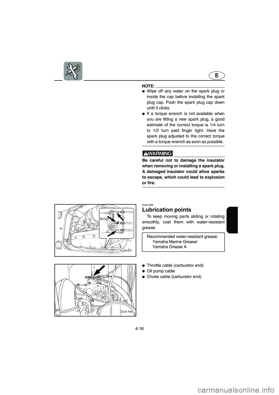
EJU01326
Lubrication points
To keep moving parts sliding or rotating
smoothly, coat them with water-resistant
grease.
Recommended water-resistant grease:
Yamaha Marine Grease/
Yamaha Grease A
�Throttle cable (carburetor end)
�Oil pump cable
�Choke cable (carburetor end)
UGU572.book Page 16 Wednesday, August 28, 2002 1:31 PM
Page 113 of 134

4-20
E
EJU01971
Inspecting the battery
Check the level of the battery electrolyte
and make sure that the negative and posi-
tive leads are securely tightened.
WARNING@ �Battery electrolyte is poisonous and
dangerous, causing severe burns, etc.
Electrolyte contains sulfuric acid.
Avoid contact with skin, eyes, or cloth-
ing.
Antidotes
External: Flush with water.
Internal: Drink large quantities of water
or milk. Follow with milk of magnesia,
beaten egg, or vegetable oil. Call phy-
sician immediately.
Eyes: Flush with water for 15 minutes
and get prompt medical attention.
Batteries produce explosive gases.
Keep sparks, flame, cigarettes, etc.,
well away. If using or charging the bat-
tery in an enclosed space, make sure
that it is well ventilated. Always shield
your eyes when working near batter-
ies.
KEEP OUT OF THE REACH OF CHIL-
DREN.
�Be sure to connect the breather hose
to the battery. Fire or explosion could
result if the breather hose is damaged,
obstructed, or not connected properly.
@
CAUTION:@ �Be careful not to place the battery on
its side.
�Be sure to remove the battery from the
battery compartment when adding
electrolyte or charging the battery.
@
UGU572.book Page 20 Wednesday, August 28, 2002 1:31 PM
Page 116 of 134
4-23
E
EJU01263
Replacing the fuse
The fuse is in the electrical box 1.
To replace the fuse:
1. Remove the cap 2, pull out the red lead,
and bring the fuse holder 3 out of the
electrical box.
2. Open the fuse holder and replace the
fuse 4 with one of the correct amper-
age.
WARNING@ Do not use fuses of higher amperage that
those recommended. Substitution of a
fuse of improper rating can cause exten-
sive electrical system damage and possi-
ble fire.
@
EJU01112
Bleeding the oil injection
pump
If the oil tank becomes completely empty,
or any hose connected to the oil pump has
been disconnected, the oil pump must be
bled to ensure proper oil flow.
If bleeding of the oil pump is necessary,
have a Yamaha dealer bleed it.Fuse amperage: 10 A
UGU572.book Page 23 Wednesday, August 28, 2002 1:31 PM