Page 50 of 130

3-1
E
EJU01798
Fuel and oil
This watercraft is equipped with a
4-stroke engine. Conventional 2-stroke
engine oil cannot be used.
The engine utilizes an electronic fuel
injection system to deliver the optimal air-
fuel mixture ratio required by the engine.
With optimal combustion conditions, this
system is able to increase startability and
improve fuel economy.
EJU19112
Gasoline
WARNING@ GASOLINE AND ITS VAPORS ARE
HIGHLY FLAMMABLE AND EXPLOSIVE!
�Do not smoke when refueling, and
keep away from sparks, flames, or
other sources of ignition.
�Stop engine before refueling.
�Refuel in a well-ventilated area with
the watercraft in a horizontal position.
�Do not stand or sit on the watercraft
while refueling in case of fire.
�Take care not to spill gasoline. If gaso-
line spills, wipe it up immediately with
dry rags. Always properly dispose of
gasoline-soaked rags.
�Avoid overfilling the fuel tank. Stop fill-
ing when the fuel level reaches approx-
imately 50 mm (2 in) from the top of the
fuel tank. Fuel expands as it warms up
and could overflow if the fuel tank has
been overfilled. If temporarily leaving
the watercraft with a full fuel tank, do
not leave it in direct sunlight. Leave it
in a well-ventilated area with the water-
craft in a horizontal position.
UF1B71.book Page 1 Tuesday, November 12, 2002 4:17 PM
Page 54 of 130

3-5
E
EJU01346
Pre-operation checks
EJU01347
Pre-operation check list
Before operating this watercraft, perform the checks in the following check list. See the
accompanying text in this chapter for details on how to perform the checks.
WARNING@ If any item in the pre-operation check list is not working properly, have it inspected
and repaired before operating the watercraft, otherwise an accident could occur.
@
NOTE:@ Pre-operation checks should be made thoroughly each time the watercraft is used. This pro-
cedure can be completed in a short time. It is worth the time spent to assure safety and reli-
ability.
@
ITEM ROUTINE PAGE
Engine compartment Remove all seats to ventilate engine compart-
ment. Check for fuel vapors or loose electrical
connections3-6
Bilge Check for water and fuel residue and remove if
necessary3-9
Throttle Check that the throttle lever springs back 3-12
Steering system Check for proper steering system operation 3-12
Shift lever and reverse gate Check for proper operation 3-13
Fuel Check fuel level and add if necessary
Check hoses and tank for leakage3-6
Engine oil Check oil level and add if necessary 3-7
Water separator Check for water and drain if necessary 3-8
Battery Check electrolyte level and battery condition 3-10
Front and rear seats Check that the seats are properly secured 2-5, 6
Hull/Deck Check the hull and deck for cracks or other dam-
age—
Jet unit Check for debris and remove if necessary 3-14
Fire extinguisher Check the condition and replace if necessary 3-11
Engine shut-off cord Check condition and replace is frayed or broken 3-14
Switches Check the start switch, engine stop switch and
engine shut-off switch for proper operation when
the watercraft is in the water3-15
Cooling water pilot outlet Check that water is discharged while the engine
is running and the watercraft is in the water3-15
Multifunction meter Check for warning indications and proper opera-
tion3-15
UF1B71.book Page 5 Tuesday, November 12, 2002 4:17 PM
Page 96 of 130

4-9
E
EJU01355
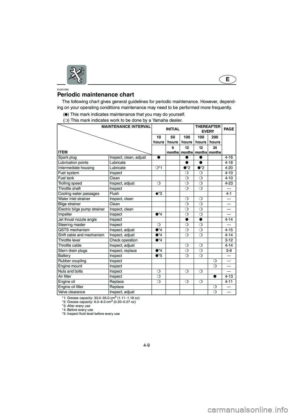
Periodic maintenance chart
The following chart gives general guidelines for periodic maintenance. However, depend-
ing on your operating conditions maintenance may need to be performed more frequently.
PMC-F1B1(�) This mark indicates maintenance that you may do yourself.
(
❍) This mark indicates work to be done by a Yamaha dealer.
MAINTENANCE INTERVAL
INITIALTHEREAFTER
EVERYPA G E
10
hours50
hours100
hours100
hours200
hours
ITEM
6
months12
months12
months24
months
Spark plug Inspect, clean, adjust���
4-16
Lubrication points Lubricate��
4-18
Intermediate housing Lubricate❍
*1�
*2�
*2 4-20
Fuel system Inspect❍❍
4-10
Fuel tank Clean❍❍
4-10
Trolling speed Inspect, adjust❍❍❍
4-23
Throttle shaft Inspect❍❍
—
Cooling water passages Flush
�*3 4-1
Water inlet strainer Inspect, clean❍❍
—
Bilge strainer Clean❍❍
—
Electric bilge pump strainer Inspect, clean❍❍
—
Impeller Inspect�
*4❍❍
—
Jet thrust nozzle angle Inspect��
4-14
Steering master Inspect❍❍❍
—
QSTS mechanism Inspect, adjust�
*4❍❍
4-15
Shift cable and mechanism Inspect, adjust�
*4❍❍
4-14
Throttle lever Check operation�
*4 3-12
Throttle cable Inspect, adjust❍❍
4-14
Stern drain plugs Inspect, replace�
*4❍❍
3-9
Battery Inspect
�*5❍❍
—
Rubber coupling Inspect❍
—
Engine mount Inspect❍
—
Nuts and bolts Inspect❍❍❍
—
Air filter Inspect❍�
4-13
Engine oil Replace❍❍❍
4-11
Engine oil filter Replace❍
—
Valve clearance Inspect, adjust❍
—
*1: Grease capacity: 33.0–35.0 cm3 (1.11–1.18 oz)
*2: Grease capacity: 6.0–8.0 cm3 (0.20–0.27 oz)
*3: After every use
*4: Before every use
*5: Inspect fluid level before every use
UF1B71.book Page 9 Tuesday, November 12, 2002 4:17 PM
Page 103 of 130

4-16
E
EJU18201
Cleaning and adjusting the
spark plugs
The spark plug is an important engine
component and is easy to inspect. The con-
dition of the spark plug can indicate some-
thing about the condition of the engine. For
example, if one spark plug shows a distinctly
different color, the engine could be defec-
tive. Do not attempt to diagnose any prob-
lems yourself. Have a Yamaha dealer
service the watercraft.
Remove and inspect the spark plug peri-
odically; heat and deposits will cause the
spark plug to slowly break down and erode.
If electrode erosion becomes excessive, or if
carbon and other deposits are excessive,
replace the spark plug with the specified
plug.
Removing a spark plug:
1. Remove the air filter case cover and air
filter element. (See page 4-13 for air filter
removal and installation procedures.)
2. Remove the spark plug.
Measure the spark plug gap a with a
wire thickness gauge. Replace the spark
plugs or adjust the gap to specification if
necessary.Specified spark plug: NGK CR9EB
Spark plug gap:
0.7–0.8 mm (0.028–0.031 in)
UF1B71.book Page 16 Tuesday, November 12, 2002 4:17 PM