Page 28 of 96

INSTRUMENT AND CONTROL FUNCTIONS
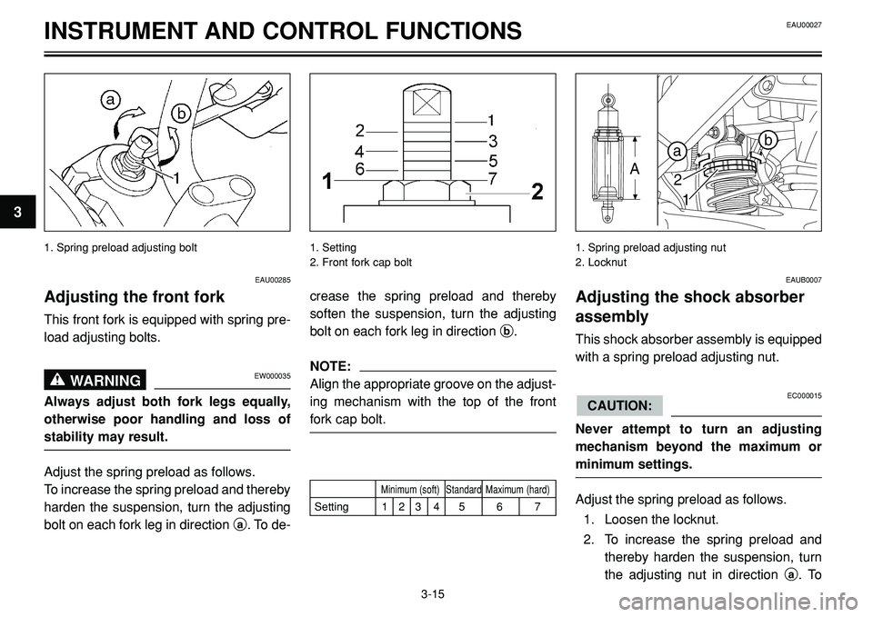
1. Spring preload adjusting bolt 1. Setting
2. Front fork cap bolt
��
�
� �
1. Spring preload adjusting nut
2. Locknut
EAU00285
Adjusting the front fork
This front fork is equipped with spring pre-
load adjusting bolts.
EW000035WARNING0
Always adjust both fork legs equally,
otherwise poor handling and loss of
stability may result.
Adjust the spring preload as follows.
To increase the spring preload and thereby
harden the suspension, turn the adjusting
bolt on each fork leg in direction a. To de-
crease the spring preload and thereby
soften the suspension, turn the adjusting
bolt on each fork leg in direction b.
NOTE:
Align the appropriate groove on the adjust-
ing mechanism with the top of the front
fork cap bolt.
EAUB0007
Adjusting the shock absorber
assembly
This shock absorber assembly is equipped
with a spring preload adjusting nut.
EC000015
Never attempt to turn an adjusting
mechanism beyond the maximum or
minimum settings.
Adjust the spring preload as follows.
1. Loosen the locknut.
2. To increase the spring preload and
thereby harden the suspension, turn
the adjusting nut in direction a. To
CAUTION:
3-15
3
EAU00027
Minimum (soft) Standard Maximum (hard)
Setting 1 2 3 4 5 6 7
Page 29 of 96

INSTRUMENT AND CONTROL FUNCTIONS
decrease the spring preload and
thereby soften the suspension, turn
the adjusting nut in direction b.
NOTE:
Use the special wrench included in the
owner’s tool kit to make the adjustment.
The spring preload setting is determined
by measuring distance A, shown in the
illustration. The longer distance A is, the
higher the spring preload; the shorter dis-
tance A is, the lower the spring preload.
With each complete turn of the adjusting
nut, distance A changes by 1.5 mm.3. Tighten the locknut to the specified
torque.• Always have a Yamaha dealer ser-
vice the shock absorber.
EAU00330
Sidestand
The sidestand is located on the left side of
the frame. Raise the sidestand or lower it
with your foot while holding the motorcycle
upright.
NOTE:
The built-in sidestand switch is part of the
ignition circuit cut-off system, which cuts
the ignition in certain situations. (See fur-
ther down for an explanation of the ignition
circuit cut-off system).
3-16
3
Spring preload:
Minimum (soft):
Distance A = 170 mm
Standard:
Distance A = 162 mm
Maximum (hard):
Distance A = 154 mm
Tightening torque:
Locknut:
45 Nm (4.5 m•kg)
EAU00315WARNING0
This shock absorber contains highly
pressurized nitrogen gas. For proper
handling, read and understand the fol-
lowing information before handling the
shock absorber. The manufacturer can-
not be held responsible for property
damage or personal injury that may
result from improper handling.
•Do not tamper with or attempt to
open the gas cylinder.
•Do not subject the shock absorber
to an open flame or other high heat
sources, otherwise it may explode
due to excessive gas pressure.
•Do not deform or damage the gas
cylinder in any way, as this will
result in poor damping perfor-
mance.
EAU00027
Page 46 of 96

EAU00462PERIODIC MAINTENANCE AND MINOR REPAIR
EAU03884
NOTE:
•The air filter needs more frequent service if you are riding in unusually wet or dusty areas.
•Hydraulic brake service
•Regularly check and, if necessary, correct the brake fluid level.
•Every two years replace the internal components of the brake master cylinders and calipers, and change the brake fluid.
•Replace the brake hoses every four years and if cracked or damaged.
6-4
6
ODOMETER READING (x 1,000 km)ANNUALN0. ITEM CHECK OR MAINTENANCE JOB
1 10203040CHECK
Rear suspension
•Check operation. √√√√
20*relay arm and
connecting arm
•Lubricate with lithium-soap-based grease.√√
pivoting points
•Check starter (choke) operation.
21
*Carburators•Adjust engine idling speed and √√ √√ √ √synchronization.
22 Engine oil•Change.√√ √√ √ √
23Engine oil filter
•Replace. √√√
element
•Check oil level and vehicle for oil
√√ √
24Final gear
leakage.oil
•Change.√√√
25Moving parts and
•Lubricate.√√√√ √
cables
•Check the air cut valve and reed valve for
26
*Air induction
damage.
√√√√ √
system
•Replace the entire air induction system if
necessary.
27
*Lights, signals and •Check operation.
√√ √√ √ √
switches•Adjust headlight beam.
Page 56 of 96

EAU00462PERIODIC MAINTENANCE AND MINOR REPAIR
EWA00012WARNING0
Because loading has an enormous
impact on the handling, braking, per-
formance and safety characteristics of
your motorcycle, you should keep the
following precautions in mind.
•NEVER OVERLOAD THE MOTOR-
CYCLE! Operation of an over-
loaded motorcycle may result in
tire damage, loss of control, or
severe injury. Make sure that the
total weight of rider, passenger,
cargo, and accessories does not
exceed the specified maximum
load for the vehicle.
•Do not carry along loosely packed
items, which can shift during a
ride.
•Securely pack the heaviest items
close to the center of the motorcy-
cle and distribute the weight even-
ly on both sides.
•Adjust the suspension and tire air
pressure with regard to the load.
•Check the tire condition and air
pressure before each ride.
6-14
6
EAU00658
Tires
To maximize the performance, durability,
and safe operation of your motorcycle,
note the following points regarding the
specified tires.
Tire air pressure
The tire air pressure should be checked
and, if necessary, adjusted before each
ride.
EW000082WARNING0
•The tire air pressure must be
checked and adjusted on cold tires
(i.e., when the temperature of the
tires equals the ambient tempera-
ture).
•The tire air pressure must be
adjusted in accordance with the
riding speed and with the total
weight of rider, passenger, cargo,
and accessories approved for this
model.
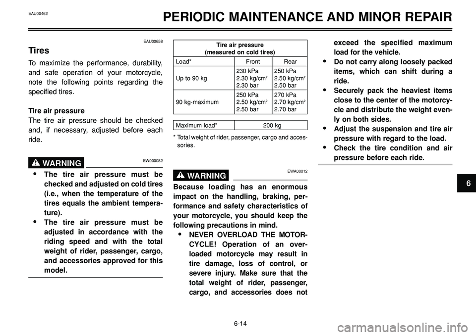
Tire air pressure(measured on cold tires)
Load* Front Rear
230 kPa 250 kPa
Up to 90 kg 2.30 kg/cm
22.50 kg/cm2
2.30 bar 2.50 bar
250 kPa 270 kPa
90 kg-maximum 2.50 kg/cm
22.70 kg/cm2
2.50 bar 2.70 bar
Maximum load* 200 kg
* Total weight of rider, passenger, cargo and acces-
sories.
Page 88 of 96
SPECIFICATIONS
8-3
8
EAU01038
Tire air pressure
(measured on cold tires)
Up to 90 kg*
Front 230 kPa; 2.30 kg/cm
2; 2.30 bar
Rear 250 kPa; 2.50 kg/cm
2; 2.50 bar
90 kg–maximum*
Front 250 kPa; 2.50 kg/cm
2; 2.50 bar
Rear 270 kPa; 2.70 kg/cm
2; 2.70 bar
* Total weight of rider, passenger, cargo and accessories
Wheels
Front
Type Cast wheel
Size 17 x MT 3.50
Rear
Type Cast wheel
Size 17 x MT 5.50
Brakes
Front:
Type Dual disc brake
Operation Right hand
Fluid DOT 4Rear:
Type Single disc brake
Operation Right foot
Fluid DOT 4
Suspension
Front: Telescopic fork
Rear: Swingarm
(link suspension)
Spring/shock absorber
Front: Coil spring / oil damper
Rear: Coil spring / gas-oil damper,
spring preload adjustable
Wheel travel
Front: 130 mm
Rear: 113 mm
Electrical system
Ignition system Transistorized coil ignition
(digital)
Charging system
Type A.C. magneto
Standard output 14V, 350W at 5,000 r/min