Page 11 of 345
’03 TUNDRA_U (L/O 0307)
2
2003 TUNDRA from Jul. ’03 Prod. (OM 34430U)
1. Side vents
2. Instrument cluster
3. Center vents
4. Personal lights
5. Garage door opener box or auxiliary
box
6. Side defroster outlet
7. Glove box
8. Power door lock switches
9. Power window switches
10. Manual transmission gear shift lever
11. Front drive control lever
12. Rear condole box
13. Cup holders
14. Parking brake lever
15. Lower vent
16. Hood lock release lever
17. Window lock switch
18. Power rear view mirror control switches
Instrument panel overview
� Vehicles with manual transmission
Page 12 of 345
’03 TUNDRA_U (L/O 0307)
3
2003 TUNDRA from Jul. ’03 Prod. (OM 34430U)
1. Side vents
2. Instrument cluster
3. Automatic transmission selector lever
4. Center vents
5. Personal lights
6. Garage door opener box or auxiliary
box
7. Side defroster outlet
8. Glove box
9. Power door lock switches
10. Power window switches
11. Auxiliary box
12. Rear condole box
13. Cup holders
14. Lower vent
15. Hood lock release lever
16. Parking brake pedal
17. Window lock switch
18. Power rear view mirror control switches
�
Vehicles with automatic transmission
Page 87 of 345
’03 TUNDRA_U (L/O 0307)
78
2003 TUNDRA from Jul. ’03 Prod. (OM 34430U)
2. Lightly push down on the top sur-
face of the anchor bracket cover,
then pull it forward to remove.3. Fix the child restraint system withthe seat belt.
Latch the hook onto the anchor
bracket and tighten the top strap.
For instructions to install the child re-
straint system, see “Child restraint” in this
section.
CAUTION
Make sure the top strap is securely
latched, and check that the child re-
straint system is secure by pushing
and pulling it in different directions.
Follow all the installation instructions
provided by its manufacturer.
4. Replace the passenger head re- straint.
Store any removed covers in a safe place
such as the glove box.
Be sure to replace all covers when the
anchor bracket is not in use.
Page 174 of 345

165
2003 TUNDRA from Jul. ’03 Prod. (OM 34430U)
OPERATION OF INSTRUMENTS AND
CONTROLS
Other equipment
Clock 166
. . . . . . . . . . . . . . . . . . . . . . . . . . . . . .")
’03 TUNDRA_U (L/O 0307)
165
2003 TUNDRA from Jul. ’03 Prod. (OM 34430U)
OPERATION OF INSTRUMENTS AND
CONTROLS
Other equipment
Clock 166
. . . . . . . . . . . . . . . . . . . . . . . . . . . . . . . . . . . . .\
. . . . . . . . . . . . . . . . .
Cigarette lighter and ashtray 166
. . . . . . . . . . . . . . . . . . . . . . . . . . . . . . . . .
Power outlets 167
. . . . . . . . . . . . . . . . . . . . . . . . . . . . . . . . . . . . \
. . . . . . . . . .
Glove box 167
. . . . . . . . . . . . . . . . . . . . . . . . . . . . . . . . . . . . \
. . . . . . . . . . . . . .
Garage door opener box 168
. . . . . . . . . . . . . . . . . . . . . . . . . . . . . . . . . . . . \
Auxiliary boxes 171
. . . . . . . . . . . . . . . . . . . . . . . . . . . . . . . . . . . . \
. . . . . . . . .
Rear console box 173
. . . . . . . . . . . . . . . . . . . . . . . . . . . . . . . . . . . . \
. . . . . . .
Coin holder 175
. . . . . . . . . . . . . . . . . . . . . . . . . . . . . . . . . . . . \
. . . . . . . . . . . .
Compact disc and cassette tape holder 177
. . . . . . . . . . . . . . . . . . . . . . .
Cassette tape holder 179
. . . . . . . . . . . . . . . . . . . . . . . . . . . . . . . . . . . . \
. . . .
Cup holders 179
. . . . . . . . . . . . . . . . . . . . . . . . . . . . . . . . . . . . \
. . . . . . . . . . . .
Note pad holder 182
. . . . . . . . . . . . . . . . . . . . . . . . . . . . . . . . . . . . \
. . . . . . . .
Floor mat 182
. . . . . . . . . . . . . . . . . . . . . . . . . . . . . . . . . . . . \
. . . . . . . . . . . . . .
SECTION 1� 9
Page 176 of 345

167
2003 TUNDRA from Jul. ’03 Prod. (OM 34430U)
Ty p e A
Ty p e B
The power outlets are designed for
power supply for car accessories.
The key must be in the “ACC” or �")
’03 TUNDRA_U (L/O 0307)
167
2003 TUNDRA from Jul. ’03 Prod. (OM 34430U)
Ty p e A
Ty p e B
The power outlets are designed for
power supply for car accessories.
The key must be in the “ACC” or “ON”
position for the power outlets to be used.
NOTICE
�To prevent the fuse from being
blown, do not use the electricity
over the total vehicle capacity of
12V/120W.
� To prevent the battery from being
discharged, do not use the power
outlets longer than necessary when
the engine is not running.
� Close the power outlet lids when
the power outlets are not in use.
Inserting a foreign object other than
the appropriate plug that fits the
outlet, or allowing any liquid into
the outlet may cause electrical fail-
ure or short circuits.
To open the glove box door, pull the
lever.
On some models, the glove box light will
come on when the glove box is opened
with the headlight switch on.
CAUTION
To reduce the chance of injury in
case of an accident or a sudden stop,
always keep the glove box door
closed while driving.
Power outlets Glove box
Page 179 of 345
’03 TUNDRA_U (L/O 0307)
170
2003 TUNDRA from Jul. ’03 Prod. (OM 34430U)
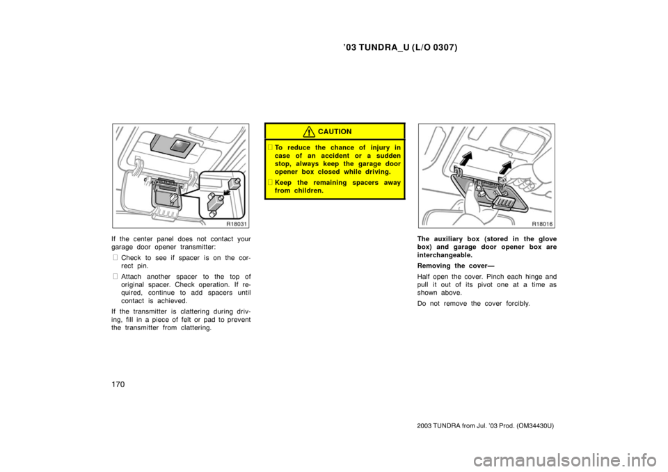
If the center panel does not contact your
garage door opener transmitter:
�Check to see if spacer is on the cor-
rect pin.
�Attach another spacer to the top of
original spacer. Check operation. If re-
quired, continue to add spacers until
contact is achieved.
If the transmitter is clattering during driv-
ing, fill in a piece of felt or pad to prevent
the transmitter from clattering.
CAUTION
�To reduce the chance of injury in
case of an accident or a sudden
stop, always keep the garage door
opener box closed while driving.
�Keep the remaining spacers away
from children.
The auxiliary box (stored in the glove
box) and garage door opener box are
interchangeable.
Removing the cover—
Half open the cover. Pinch each hinge and
pull it out of its pivot one at a time as
shown above.
Do not remove the cover forcibly.
Page 235 of 345

226
2003 TUNDRA from Jul. ’03 Prod. (OM 34430U)
MATCHING TRAILER BALL HEIGHT TO
TRAILER COUPLER HEIGHT
No matter which class of tow hitch ap-
plies, for a safe trailer hook")
’03 TUNDRA_U (L/O 0307)
226
2003 TUNDRA from Jul. ’03 Prod. (OM 34430U)
MATCHING TRAILER BALL HEIGHT TO
TRAILER COUPLER HEIGHT
No matter which class of tow hitch ap-
plies, for a safe trailer hookup, the trailer
ball setup on must be the proper height
for the coupler on the trailer.
BRAKES AND SAFETY CHAINS
�Toyota recommends trailers with
brakes that conform to any applica-
ble federal and state/provincial regu-
lations.
�A safety chain must always be used
between the towing vehicle and the
trailer. Leave sufficient slack in the
chain for turns. The chain should
cross under the trailer tongue to
prevent the tongue from dropping to
the ground in case it becomes dam-
aged or separated. For correct safety
chain procedures, follow the hitch or
trailer manufacturer ’s recommenda-
tions.
CAUTION
�If the total trailer weight exceeds
453 kg (1000 lb.), trailer brakes are
required.
�Never tap into your vehicle’s hy-
draulic system as it would lower its
braking effectiveness.
�Never tow a trailer without using a
safety chain securely attached to
both the trailer and the vehicle. If
damage occurs to the coupling unit
or hitch ball, there is danger of the
trailer wandering over into another
lane.
SERVICE CONNECTOR FOR TOWING
BRAKE CONTROLLER (with towing
package)
Your vehicle is equipped with a service
connector for the towing brake controller
as shown. Link the connector to the tow-
ing brake controller via the sub wire har-
ness stored in the glove box. The detailed
explanation of the sub wire harness circuit
is packed together with the sub wire har-
ness.
Be sure to position the towing brake con-
troller where it does not prevent the driver
from operating the pedal.
Toyota recommends that the sub wire har-
ness be stored in the glove box when it
is not in use.
Page 310 of 345
’03 TUNDRA_U (L/O 0307)
301
2003 TUNDRA from Jul. ’03 Prod. (OM 34430U)
Light bulbsBulb
No.WTy p e
Door courtesy
lights1943.8D
Glove box light—1.2D
Step light—1.4D
A: HB2 halogen bulbs
B: HB4 halogen bulbs
C: Wedge base bulbs (amber)
D: Wedge base bulbs
E: Double end bulbs
1. Open the hood. Unplug the connec-
tor. Remove the rubber cover.
If the connector is tight, wiggle it.2. Release the bulb retaining spring and remove the bulb. Install a new
bulb and the bulb retaining spring.
To install a bulb, align the tabs of the
bulb with the cutouts of the mounting
hole.
—Headlights

2
2003 TUNDRA from Jul. ’03 Prod. (OM 34430U)
1. Side vents
2. Instrument cluster
3. Center vents
4. Personal lights
5. Garage door opener box or auxiliary
box
6. Side defr")

3
2003 TUNDRA from Jul. ’03 Prod. (OM 34430U)
1. Side vents
2. Instrument cluster
3. Automatic transmission selector lever
4. Center vents
5. Personal lights
6. Garage door")

78
2003 TUNDRA from Jul. ’03 Prod. (OM 34430U)
2. Lightly push down on the top sur-
face of the anchor bracket cover,
then pull it forward to remove.3. Fix the child restra")

301
2003 TUNDRA from Jul. ’03 Prod. (OM 34430U)
Light bulbsBulb
No.WTy p e
Door courtesy
lights1943.8D
Glove box light—1.2D
Step light—1.4D
A: HB2 halogen bulbs
B: HB4")