Page 24 of 2234
NEW MODEL OUTLINE
����\b��
����\b��
Sedan Model Liftback Model
����\b��
MO-22
Rear Sunshade
A hand-operated rear sun shade is available as an option for Europe sedans and liftback \
models
and is standard equipment on General Countries sedan models.
Power Outlet
The back surface of the console is equipped with a 12V-120W power outlet for MID TECHNICAL
and MID ELEGANT grade only.
Wiper System
�A wiper system with raindrop sensing function is standard equipment on MID TECHNICAL
and MID ELEGANT grade models.
� Raindrop sensing function: When the wiper switch is in the auto position, a rain sensor b\
uilt
into the windshield glass detects the amount of raindrops and causes the\
wipers to operate
automatically at the optimum timing for that amount.
http://vnx.su
Page 31 of 2234
MO
NEW MODEL OUTLINEMO-29
�
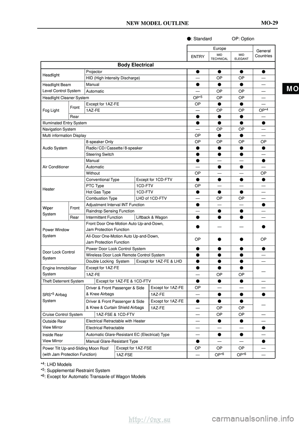
: Standard OP: Option
EuropeGeneral
ENTRYMID
TECHNICALMID
ELEGANTGeneralCountries
Body Electrical
HeadlightProjector����HeadlightHID (High lntensity Discharge)ÐOPOPÐ
Headlight BeamManual���Ð
Level Control SystemAutomaticÐOPOPÐ
Headlight Cleaner SystemOP*5OPOPÐ
FrontExcept for 1AZ-FEOP��Ð
Fog LightFront1AZ-FEÐOPOPOP*4
Rear���Ð
Illuminated Entry System����
Navigation SystemÐOPOPÐ
Multi information DisplayOP��Ð
8-speaker OnlyOPOPOPOP
Audio SystemRadio / CD / Cassette / 8-speaker����
Steering Switch���Ð
Manual�ÐÐ�
Air ConditionerAutomaticÐ��Ð
WithoutOPÐÐOP
Conventional TypeExcept for 1CD-FTV����
HeaterPTC Type1CD-FTVOPÐÐÐHeaterHot Gas Type1CD-FTV���Ð
Combustion TypeLHD of 1CD-FTVÐOPOPÐ
WiperFrontAdjustment Interval INT Function�ÐÐ�Wiper
SystemFrontRaindrop Sensing FunctionÐ��ÐSystemRearIntermittent FunctionLiftback & Wagon���Ð
Power Window
Front Door One-Motion Auto Up-and-Down,
Jam Protection Function�ÐÐ�
SystemAll-Door One-Motion Auto Up-and-Down,
Jam Protection FunctionOP��OP
Door Lock ControlPower Door Look Control System����Door Lock Control
SystemWireless Door Look Remote Control System���ÐSystemDouble Locking SystemExcept for 1AZ-FE & LHD���Ð
Engine ImmobiliserExcept for 1AZ-FE���
System1AZ-FEÐOPOPÐ
Theft Deterrent SystemExcept for 1AZ-FE & 1CD-FTV���Ð
5
Driver & Front Passenger & SideExcept for 1AZ-FEOPÐÐÐ
SRS*5 Airbag& Knee Airbags1AZ-FE���
SystemDriver & Front Passenger & SideExcept for 1AZ-FE���
& Knee & Curtain Shield Airbags1AZ-FEÐOPOPÐ
Cruise Control System1AZ-FSE & 1CD-FTVÐOPOPÐ
Outside RearElectrical Retractable with HeaterÐ��Ð
View MirrorElectrical RetractableÐÐÐ�
Inside RearAutomatic Glare-Resistant EC (Electrical) TypeÐ��Ð
View MirrorManual Glare-Resistant Type�ÐÐ�
Power Tilt Up-and-Sliding Moon RoofExcept for 1AZ-FSEOPOPOPÐ
(with Jam Protection Function)1AZ-FSEÐOP*6OP*6Ð
*4: LHD Models
*5: Supplemental Restraint System
*6: Except for Automatic Transaxle of Wagon Models
http://vnx.su
Page 157 of 2234
022KW±01
02±54
±
PREPARATION WIPER & WASHER
AVENSIS REPAIR MANUAL (RM1018E)
WIPER & WASHER
PREPARATION
SST
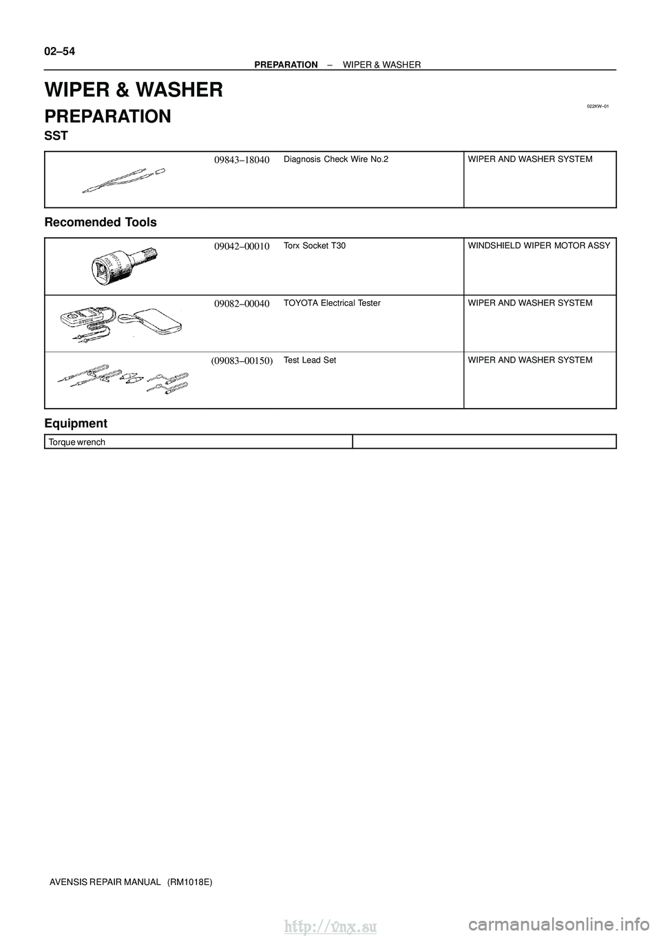
09843±18040Diagnosis Check Wire No.2WIPER AND WASHER SYSTEM
Recomended Tools
09042±00010Torx Socket T30WINDSHIELD WIPER MOTOR ASSY
09082±00040TOYOTA Electrical TesterWIPER AND WASHER SYSTEM
(09083±00150)Test Lead SetWIPER AND WASHER SYSTEM
Equipment
Torque wrench
http://vnx.su
Page 232 of 2234
031HA±01
03±66
±
SERVICE SPECIFICATIONS WIPER & WASHER
AVENSIS REPAIR MANUAL (RM1018E)
WIPER & WASHER
TORQUE SPECIFICATION
Part TightenedN �mkgf �cmft �lbf
Wiper motor x Wiper link7.57666 in.� lbf
Wiper link x Body5.55649 in.�lbf
Wiper arm x Wiper link2121015
Rear wiper motor x Body5.55649 in.�lbf
Rear wiper motor x Rear wiper arm5.55649 in.�lbf
http://vnx.su
Page 237 of 2234

������������
3020
10
5
3
02040
0.1 1
0.3 0.2
0.5 2
60 80 100
±20
(±4) (104) (140) (176)
(32) (68) (212)
Z17274
Ohmmeter
Acceptable
Temperature �C (� F)
Resistance k�
THF E2
A30331
30
20
10
�
�
�
�
0.5
0.3
0.2
0.1
±20 �
20 40 60
80 100
F14741(±4) (104) (140) (176)
(32) (68) (212)
A56276
Temperature �C (� F)
Resistance k�
±
ENGINE CONTROL SYSTEM ECD SYSTEM (1CD±FTV)
10±57
AVENSIS REPAIR MANUAL (RM1018E)
3. INSPECT DIESEL ENGINE ENGINE COOLANT
TEMPERATURE SENSOR
(a) Resistance inspection.
(1) Using an ohmmeter, measure the resistance be-tween each terminal.
Resistance:
Approx. 20 �C (68� F) 2.32 to 2.59 k �
Approx. 80 �C (176� F) 0.310 to 0.326 k�
NOTICE:
In case of checking the water temperature sensor in the wa-
ter, be careful not to allow water to go into the terminals,
and after checking, wipe out the sensor.
4. INSPECT INJECTION OR SUPPLY PUMP ASSY
(a) Resistance inspection. (Fuel temperature sensor) (1) Using an ohmmeter, measure the resistance be-tween each terminal.
Resistance:
Approx. 20 �C (68� F) 2.21 to 2.69 k �
Approx. 80 �C (176� F) 0.287 to 0.349 k�
5. INSPECT DIESEL TURBO INLET AIR TENPERATURE SENSOR
(a) Resistance inspection. (1) Using an ohmmeter, measure the resistance be-
tween each terminal.
Resistance:
Approx. 20 �C (68� F) 2.21 to 2.65 k �
http://vnx.su
Page 270 of 2234
TEMPERATURE�C( �F)
RESISTANCE k�
30
20
10
5
2
1
0.5
0.3
0.2
0.1 3
±20 0 20 40 60 80 100
(±4) (32) (80) (140)(104)
(212)
(176)
A50371
A65174
Ohmmeter
E34090
10±22
±
ENGINE CONTROL SYSTEM SFI SYSTEM (1AZ±FE)
AVENSIS REPAIR MANUAL (RM1018E)
5. INSPECT ENGINE COOLANT TEMPERA TURE
SENSOR
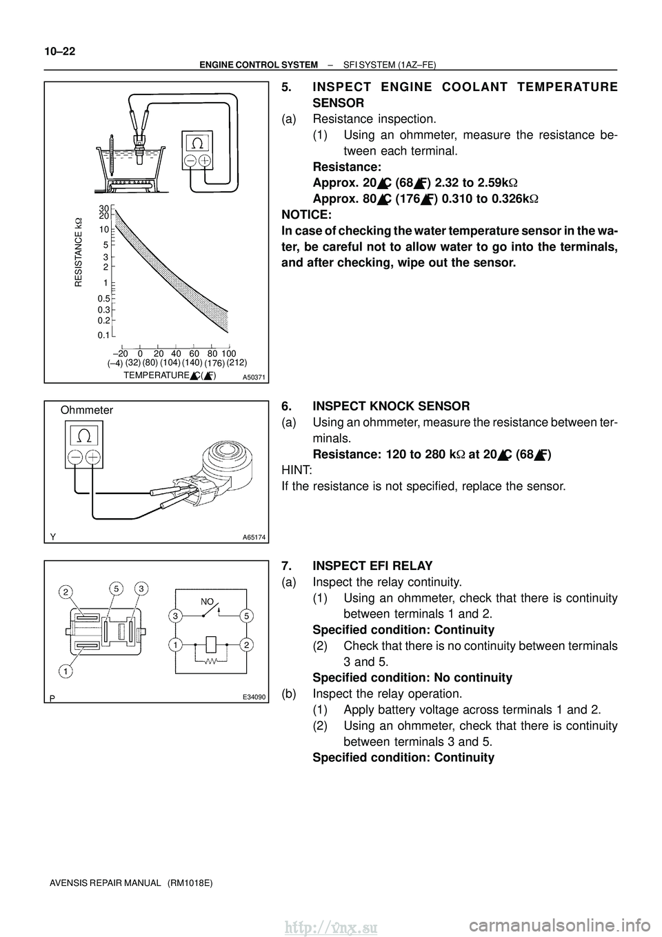
(a) Resistance inspection.
(1) Using an ohmmeter, measure the resistance be-tween each terminal.
Resistance:
Approx. 20 �C (68� F) 2.32 to 2.59k�
Approx. 80 �C (176� F) 0.310 to 0.326k �
NOTICE:
In case of checking the water temperature sensor in the wa-
ter, be careful not to allow water to go into the terminals,
and after checking, wipe out the sensor.
6. INSPECT KNOCK SENSOR
(a) Using an ohmmeter, measure the resistance between ter- minals.
Resistance: 120 to 280 k �at 20� C (68� F)
HINT:
If the resistance is not specified, replace the sensor.
7. INSPECT EFI RELAY
(a) Inspect the relay continuity.
(1) Using an ohmmeter, check that there is continuitybetween terminals 1 and 2.
Specified condition: Continuity
(2) Check that there is no continuity between terminals 3 and 5.
Specified condition: No continuity
(b) Inspect the relay operation. (1) Apply battery voltage across terminals 1 and 2.
(2) Using an ohmmeter, check that there is continuitybetween terminals 3 and 5.
Specified condition: Continuity
http://vnx.su
Page 275 of 2234

TEMPERATURE�C( �F)
RESISTANCE k�
30
20
10
5
2
1
0.5
0.3
0.2
0.1 3
±20 0 20 40 60 80 100
(±4) (32) (80) (140)(104)
(212)
(176)
A50371
A65174
Ohmmeter
E34090
10±40
±
ENGINE CONTROL SYSTEM SFI SYSTEM (1AZ±FSE)
AVENSIS REPAIR MANUAL (RM1018E)
4. INSPECT ENGINE COOLANT TEMPERA TURE
SENSOR
(a) Resistance inspection.
(1) Using an ohmmeter, measure the resistance be-tween each terminal.
Resistance:
Approx. 20 �C (68� F) 2.32 to 2.59k�
Approx. 80 �C (176� F) 0.310 to 0.326k �
NOTICE:
In case of checking the water temperature sensor in the wa-
ter, be careful not to allow water to go into the terminals,
and after checking, wipe out the sensor.
5. INSPECT KNOCK SENSOR
(a) Using an ohmmeter, measure the resistance between ter- minals.
Resistance: 120 to 280 k �at 20� C (68� F)
HINT:
If the resistance is not specified, replace the sensor.
6. INSPECT EFI RELAY
(a) Inspect the relay continuity.
(1) Using an ohmmeter, check that there is continuitybetween terminals 1 and 2.
Specified condition: Continuity
(2) Check that there is no continuity between terminals 3 and 5.
Specified condition: No continuity
(b) Inspect the relay operation. (1) Apply battery voltage across terminals 1 and 2.
(2) Using an ohmmeter, check that there is continuitybetween terminals 3 and 5.
Specified condition: Continuity
http://vnx.su
Page 281 of 2234
A60552
30
20
105
3
2
1
0.5
0.3
0.2
0.1
RESISTANCE k�
±20 0 20 40 60 80 100 (±4)
TEMPERATURE �C( �F)
(32) (68) (104)(140)(176)(212)
A65174
Ohmmeter
A60553
±
ENGINE CONTROL SYSTEM SFI SYSTEM (1ZZ±FE/3ZZ±FE)
10±5
AVENSIS REPAIR MANUAL (RM1018E)
5. INSPECT ENGINE COOLANT TEMPERA TURE
SENSOR
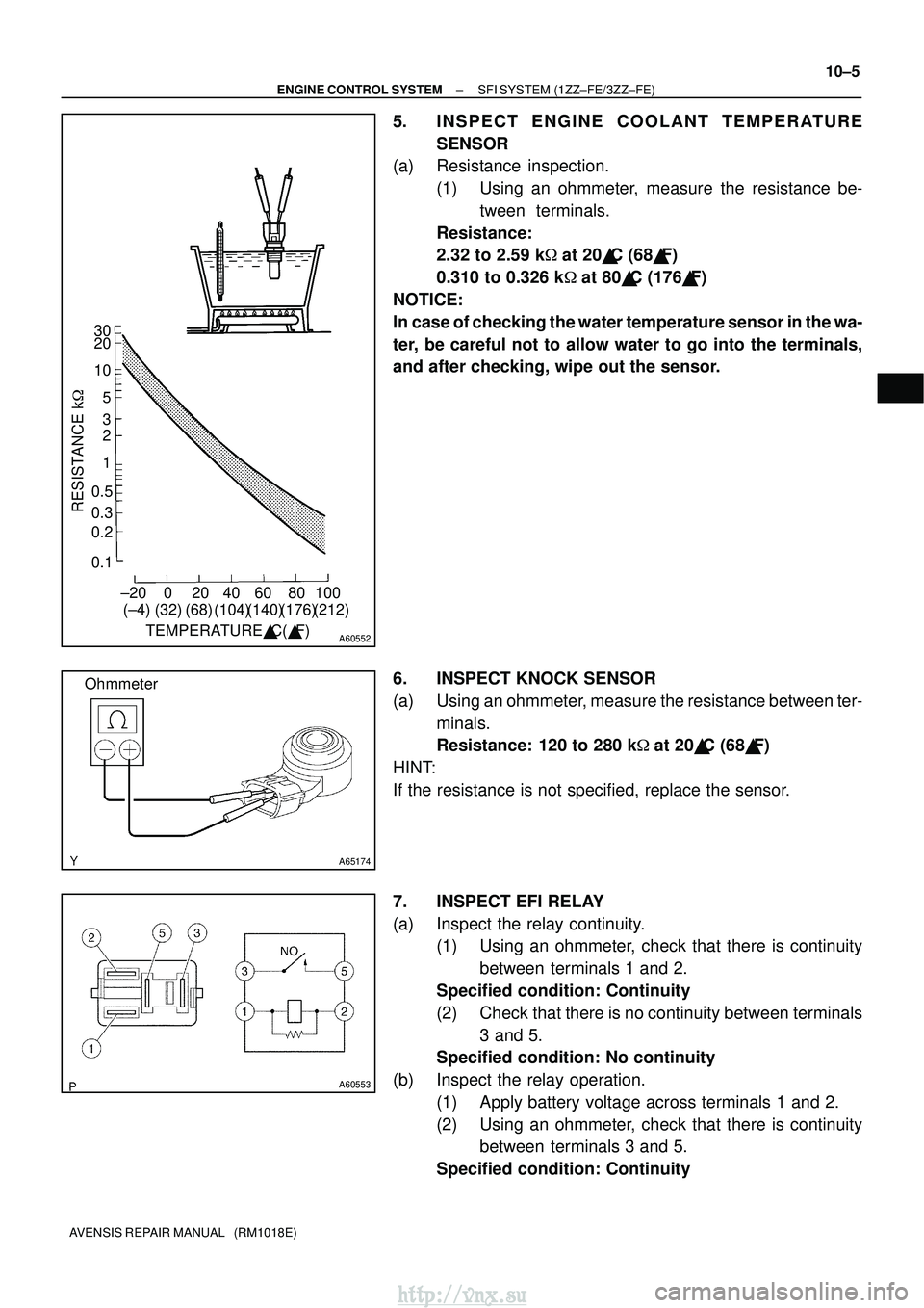
(a) Resistance inspection.
(1) Using an ohmmeter, measure the resistance be-tween terminals.
Resistance:
2.32 to 2.59 k �at 20� C (68� F)
0.310 to 0.326 k �at 80� C (176� F)
NOTICE:
In case of checking the water temperature sensor in the wa-
ter, be careful not to allow water to go into the terminals,
and after checking, wipe out the sensor.
6. INSPECT KNOCK SENSOR
(a) Using an ohmmeter, measure the resistance between ter- minals.
Resistance: 120 to 280 k �at 20� C (68� F)
HINT:
If the resistance is not specified, replace the sensor.
7. INSPECT EFI RELAY
(a) Inspect the relay continuity. (1) Using an ohmmeter, check that there is continuity
between terminals 1 and 2.
Specified condition: Continuity
(2) Check that there is no continuity between terminals 3 and 5.
Specified condition: No continuity
(b) Inspect the relay operation. (1) Apply battery voltage across terminals 1 and 2.
(2) Using an ohmmeter, check that there is continuitybetween terminals 3 and 5.
Specified condition: Continuity
http://vnx.su