Page 1558 of 2234
670SJ±01
I35195
I35197Claw
I35196
I35205
±
AUDIO & VISUAL SYSTEM CIGARETTE LIGHTER ASSY
67±29
AVENSIS REPAIR MANUAL (RM1018E)
CIGARETTE LIGHTER ASSY
REPLACEMENT
1.REMOVE CONSOLE PANEL SUB±ASSY UPPER (See page 71±11)
2. REMOVE FRONT ASH RECEPTACLE ASSY
(a) Using a torx socket wrench (T20), remove the 4 screwsand front ash receptacle assy.
3. RE MO V E FRO NT AS H RE CE P TACLE RE TAINE R SUB±ASSY
(a) Disengage the claw and disconnect the connector.
(b) Push up the corner of the outer case open and remove the retainer assy as shown in the illustration.
4. REMOVE CIGARETTE LIGHTER ASSY
(a) Remove the 2 springs.
http://vnx.su
Page 1559 of 2234
I351992 Claws
I35200
I35203
I35204
5.0mm
(0.20in.)
I35205
67±30
±
AUDIO & VISUAL SYSTEM CIGARETTE LIGHTER ASSY
AVENSIS REPAIR MANUAL (RM1018E)
(b) Disengage the 2 claws and remove the door.
(c) Push out the cigarette lighter housing to the room side.
(d) Push out the cigarette lighter ring w/ wire harness to the room side.
5. INSTALL CIGARETTE LIGHTER ASSY
(a) Align the claws of the cigarette lighter ring with the notches of the cigarette lighter box to fix the cigarette
lighter w/ wire harness.
(b) Push the cigarette lighter housing to the out side.
(c) Install the wire harness as shown in the illustration.
(d) Place the wire harness in the position shown in the il- lustration and install the door cover.
(e) Install the 2 springs.
http://vnx.su
Page 1560 of 2234
I35206
I35195
±
AUDIO & VISUAL SYSTEM CIGARETTE LIGHTER ASSY
67±31
AVENSIS REPAIR MANUAL (RM1018E)
(f) Make sure that the 2 springs are hooked on the claws and
install the retainer assy.
(g) Connect the connecter.
(h) Using a torx socket wrench (T20), install the 4 screws and
front ash receptacle.
http://vnx.su
Page 1561 of 2234

(1)
(3)
H02440
Riveter
Mandrel
67±10
±
AUDIO & VISUAL SYSTEM FRONT NO.1 SPEAKER ASSY
AVENSIS REPAIR MANUAL (RM1018E)
FRONT NO.1 SPEAKER ASSY
REPLACEMENT
1.")
670S8±01
������I35168
������I35169
(2)
(1)
(3)
H02440
Riveter
Mandrel
67±10
±
AUDIO & VISUAL SYSTEM FRONT NO.1 SPEAKER ASSY
AVENSIS REPAIR MANUAL (RM1018E)
FRONT NO.1 SPEAKER ASSY
REPLACEMENT
1. REMOVE REAR DOOR WINDOW REGULATOR HANDLE ASSY (W/O POWER WINDOW) (See page 75±8)
2.REMOVE FRONT DOOR LOWER FRAME BRACKET GARNISH LH (See page 75±8)
3.REMOVE FRONT DOOR TRIM BASE LH (See page 75±8)
4.REMOVE FUEL LID OPENER SWITCH (See page 75±8)
5. REMOVE POWER WINDOW REGULATOR SWITCH ASSY (W/ POWER WINDOW) (See page 75±8)
6.REMOVE FRONT DOOR TRIM BOARD SUB±ASSY LH (See page 75±8)
7. REMOVE FRONT NO.1 SPEAKER ASSY
(a) Disconnect the connector.
(b) Using a drill of less then � 4 mm (0.16 in.), drill out the 3
rivet heads and remove the front No.1 speaker assy from
the front door panel.
(c) Gently and vertically put the drill to the rivet, and cut the rivet flanges.
NOTICE:
�Prizing the hole with a drill can lead to damage to the
rivet hole or breaking the drill.
�Take care as the cut rivet is hot.
(d) Even if flange is taken off, continue drilling and push out remaining fragments with the drill.
(e) Using a vacuum cleaner, remove the drilled rivet and their
dust from the inside of the front door panel.
8. INSTALL FRONT NO.1 SPEAKER ASSY
(a) Using an air riveter or a hand riveter, install 3 new strike rivets to install the front No.1 speaker assy on the front
door panel.
NOTICE:
�Install the new strike rivet in order shown in the il-
lustration to install the front No.1 speaker assy.
�Do not prize a riveter, as the riveter could be dam-
aged, loosened and the mandrel could be bent.
http://vnx.su
Page 1562 of 2234
H02441
RiveterRiveter
H02442
Riveter
±
AUDIO & VISUAL SYSTEM FRONT NO.1 SPEAKER ASSY
67±11
AVENSIS REPAIR MANUAL (RM1018E)
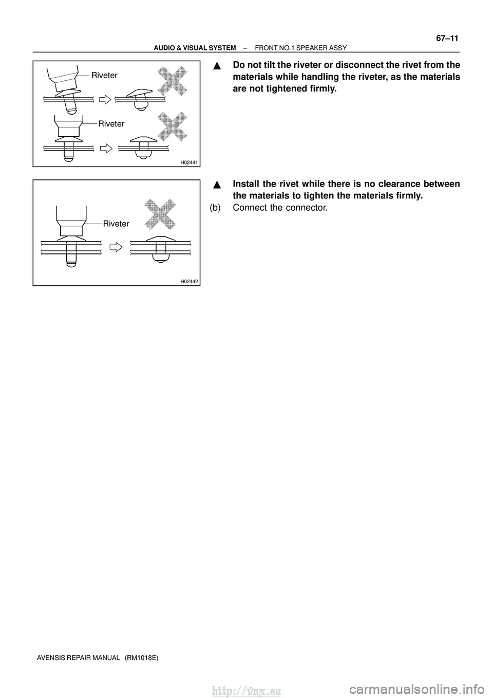
�Do not tilt the riveter or disconnect the rivet from the
materials while handling the riveter, as the materials
are not tightened firmly.
�Install the rivet while there is no clearance between
the materials to tighten the materials firmly.
(b) Connect the connector.
http://vnx.su
Page 1563 of 2234
670S9±01
I351923Clamps
67±12
±
AUDIO & VISUAL SYSTEM FRONT NO.2 SPEAKER ASSY
AVENSIS REPAIR MANUAL (RM1018E)
FRONT NO.2 SPEAKER ASSY
REPLACEMENT
1. REMOVE FRONT NO.2 SPEAKER ASSY
(a) Remove the front door lower frame bracket garnish.
(b) Disconnect the connector.
(c) Disengage the 3 claws and remove the front No.2 speak- er assy.
http://vnx.su
Page 1564 of 2234
670S7±01
I351712 Claws
I35172
I35173
I35175
67±6
±
AUDIO & VISUAL SYSTEM MULTI±DISPLAY (CRT DISPLAY) DISPLAY
AVENSIS REPAIR MANUAL (RM1018E)
MULTI±DISPLAY (CRT DISPLAY) DISPLAY
REPLACEMENT
1.REMOVE INSTRUMENT CLUSTER FINISH PANEL GARNISH NO.2 (See page 71±11) 2. REMOVE INSTRUMENT PANEL REGISTER ASSYCTR
(a) Remove the 2 screws.
(b) Disengage the 2 claws and remove the instrument panel register assy CTR.
(c) Disconnect the connectors.
3. REMOVE DOOR CONTROL SWITCH
(a) Remove the 2 screws and separate the door control switch.
4. REMOVE DOOR CONTROL SWITCH ASSY
(a) Remove the 2 screws and separate the door control switch assy (TILT).
5. REMOVE INSTRUMENT CLUSTER FINISH PANEL ASSY
(a) Make the multi±display upright.
http://vnx.su
Page 1565 of 2234
I35174
I35177
I35176
I351782 Clips
I35179
±
AUDIO & VISUAL SYSTEM MULTI±DISPLAY (CRT DISPLAY) DISPLAY
67±7
AVENSIS REPAIR MANUAL (RM1018E)
(b) Remove the 4 screws and the instrument cluster finish
panel assy.
6. REMOVE CONTROL KNOB PROTECTOR NO.1
(a) Remove the screw and control knob protector No.1.
(b) Separate the position sensor.
7. REMOVE MULTI±DISPLAY (CRT DISPLAY) DISPLAY
(a) Remove the 4 screws and separate the navigation com- puter cover.
(b) Disengage the 2 clips, slide them in the arrow direction shown in the illustration to remove the navigation comput-
er cover.
(c) Slide the lock of the connector in the arrow direction shown in the illustration to disconnect the flexible flat
cable.
http://vnx.su

CIGARETTE LIGHTER ASSY
REPLACEMENT
1.REMOVE CONSOLE PANEL SUB±ASSY U")

I35205
67±30
±
AUDIO & VISUAL SYSTEM CIGARETTE LIGHTER ASSY
AVENSIS REPAIR MANUAL (RM1018E)
(b) Disengage the 2 claws and remove the door.
(c) P")

(f) Make sure that the 2 springs are hooked on the claws and
install the retainer assy.
(g) Conne")

FRONT NO.2 SPEAKER ASSY
REPLACEMENT
1. REMOVE FRONT NO.2 SPEAKER ASSY
(a) Remove the f")
 DISPLAY
AVENSIS REPAIR MANUAL (RM1018E)
MULTI±DISPLAY (CRT DISPLAY) DISPLAY
REPLACEMENT
1.RE")
 DISPLAY
67±7
AVENSIS REPAIR MANUAL (RM1018E)
(b) Remove the 4 screws and the instrument cluster finis")