Page 723 of 2234
A01132
A60622
A01045
A64005
14±8
±
ENGINE MECHANICAL VALVE CLEARANCE (1ZZ±FE/3ZZ±FE)
AVENSIS REPAIR MANUAL (RM1018E)
(b) Turn the crankshaft 1 revolution (360 �) and set No. 4 cyl-
inder to TDC/compression.
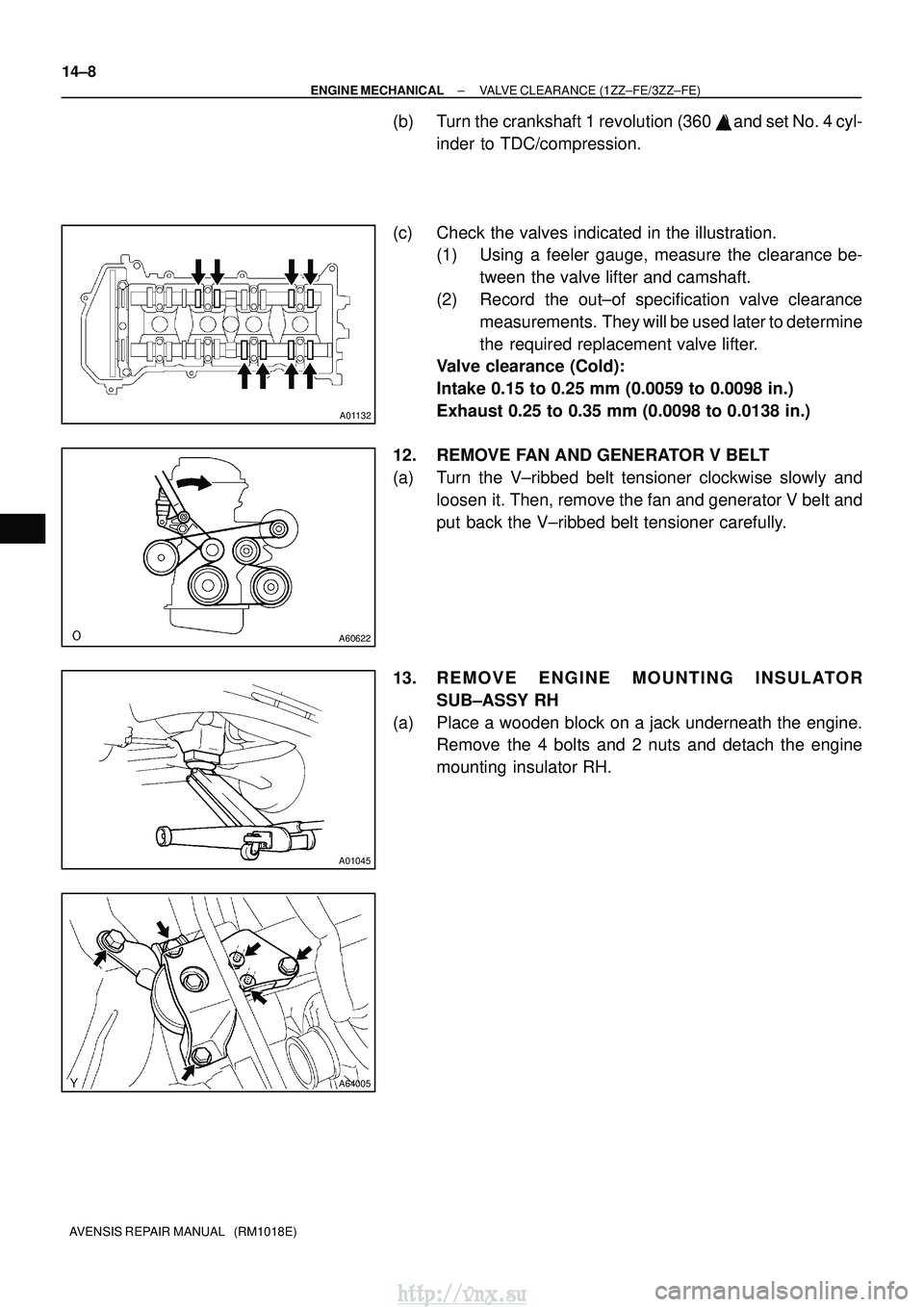
(c) Check the valves indicated in the illustration. (1) Using a feeler gauge, measure the clearance be-
tween the valve lifter and camshaft.
(2) Record the out±of specification valve clearance measurements. They will be used later to determine
the required replacement valve lifter.
Valve clearance (Cold):
Intake 0.15 to 0.25 mm (0.0059 to 0.0098 in.)
Exhaust 0.25 to 0.35 mm (0.0098 to 0.0138 in.)
12. REMOVE FAN AND GENERATOR V BELT
(a) Turn the V±ribbed belt tensioner clockwise slowly and loosen it. Then, remove the fan and generator V belt and
put back the V±ribbed belt tensioner carefully.
13. REMOVE ENGINE MOUNTING INSULATOR SUB±ASSY RH
(a) Place a wooden block on a jack underneath the engine. Remove the 4 bolts and 2 nuts and detach the engine
mounting insulator RH.
http://vnx.su
Page 786 of 2234
EM1628
EM2011
EM2538
±
ENGINE MECHANICAL PARTIAL ENGINE ASSY (1ZZ±FE/3ZZ±FE)
14±13
1ZZ±FE,3ZZ±FE ENGINE REPAIR MANUAL
(RM923E)
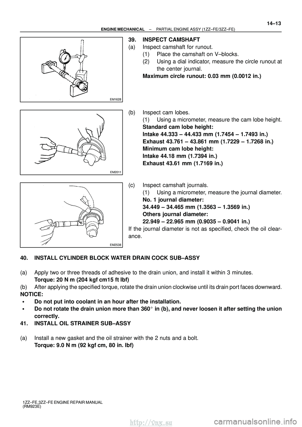
39. INSPECT CAMSHAFT
(a) Inspect camshaft for runout.
(1) Place the camshaft on V±blocks.
(2) Using a dial indicator, measure the circle runout at
the center journal.
Maximum circle runout: 0.03 mm (0.0012 in.)
(b) Inspect cam lobes. (1) Using a micrometer, measure the cam lobe height.
Standard cam lobe height:
Intake 44.333 ± 44.433 mm (1.7454 ± 1.7493 in.)
Exhaust 43.761 ± 43.861 mm (1.7229 ± 1.7268 in.)
Minimum cam lobe height:
Intake 44.18 mm (1.7394 in.)
Exhaust 43.61 mm (1.7169 in.)
(c) Inspect camshaft journals. (1) Using a micrometer, measure the journal diameter.
No. 1 journal diameter:
34.449 ± 34.465 mm (1.3563 ± 1.3569 in.)
Others journal diameter:
22.949 ± 22.965 mm (0.9035 ± 0.9041 in.)
If the journal diameter is not as specified, check the oil clear-
ance.
40. INSTALL CYLINDER BLOCK WATER DRAIN COCK SUB±ASSY
(a) Apply two or three threads of adhesive to the drain union, and install i\
t within 3 minutes. Torque: 20 N �m (204 kgf� cm15 ft�lbf)
(b) After applying the specified torque, rotate the drain union clockwise until i\
ts drain port faces downward.
NOTICE:
�Do not put into coolant in an hour after the installation.
�Do not rotate the drain union more than 360� in (b), and never loosen it after setting the union
correctly.
41. INSTALL OIL STRAINER SUB±ASSY
(a) Install a new gasket and the oil strainer with the 2 nuts and a bolt. Torque: 9.0 N �m (92 kgf �cm, 80 in. �lbf)
http://vnx.su
Page 793 of 2234
A62837SST
A62180
DisconnectHook
Pin Turn
A62181
Plunger
Turn
Push
A10085
A62179
A
ABB
B
B
14±20
±
ENGINE MECHANICAL PARTIAL ENGINE ASSY (1ZZ±FE/3ZZ±FE)
1ZZ±FE,3ZZ±FE ENGINE REPAIR MANUAL
(RM923E)
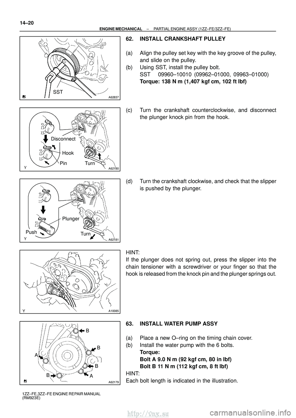
62. INSTALL CRANKSHAFT PULLEY
(a) Align the pulley set key with the key groove of the pulley, and slide on the pulley.
(b) Using SST, install the pulley bolt. SST 09960±10010 (09962±01000, 09963±01000)
Torque: 138 N� m (1,407 kgf�cm, 102 ft� lbf)
(c) Turn the crankshaft counterclockwise, and disconnect the plunger knock pin from the hook.
(d) Turn the crankshaft clockwise, and check that the slipper is pushed by the plunger.
HINT:
If the plunger does not spring out, press the slipper into the
chain tensioner with a screwdriver or your finger so that the
hook is released from the knock pin and the plunger springs out.
63. INSTALL WATER PUMP ASSY
(a) Place a new O±ring on the timing chain cover.
(b) Install the water pump with the 6 bolts. Torque:
Bolt A 9.0 N� m (92 kgf�cm, 80 in� lbf)
Bolt B 11 N� m (112 kgf�cm, 8 ft� lbf)
HINT:
Each bolt length is indicated in the illustration.
http://vnx.su
Page 798 of 2234
A62185
MarkMark
Mark Timing Chain
Cover Surface
Groove
A62177
Raise
Push
Hook
Pin
A62178
Push
A62180
Disconnect
Hook
Pin Turn
±
ENGINE MECHANICAL PARTIAL ENGINE ASSY (1ZZ±FE/3ZZ±FE)
14±25
1ZZ±FE,3ZZ±FE ENGINE REPAIR MANUAL
(RM923E)
(t) Check the match marks on the timing chain and camshaft
timing sprockets, and then the alignment of the pulley
groove with timing mark of the chain cover as shown in the
illustration.
(u) Install chain tensioner. (1) Check the O±ring is clean, and set the hook asshown in the illustration.
(2) Apply engine oil to the chain tensioner and install it.
Torque: 9.0 N� m (92 kgf�cm, 80 in� lbf)
NOTICE:
When installing the tensioner, set the hook again if the
hook release the plunger.
(3) Turn the crankshaft counterclockwise, and discon-nect the plunger knock pin from the hook.
http://vnx.su
Page 1236 of 2234
F44800
Marks
F44801
Torx ScrewScrew Case
±
STEERING COLUMN STEERING COLUMN ASSY
50±19
AVENSIS REPAIR MANUAL (RM1018E)
54.INSTALL INSTRUMENT PANEL AIR BAG ASSY (See page 60±54)
55. INSTALL COLUMN HOLE COVER SILENCER SHEET
56. PLACE FRONT WHEELS FACING STRAIGHT AHEAD
57.INSTALL SPIRAL CABLE SUB±ASSY (See page 60±26)
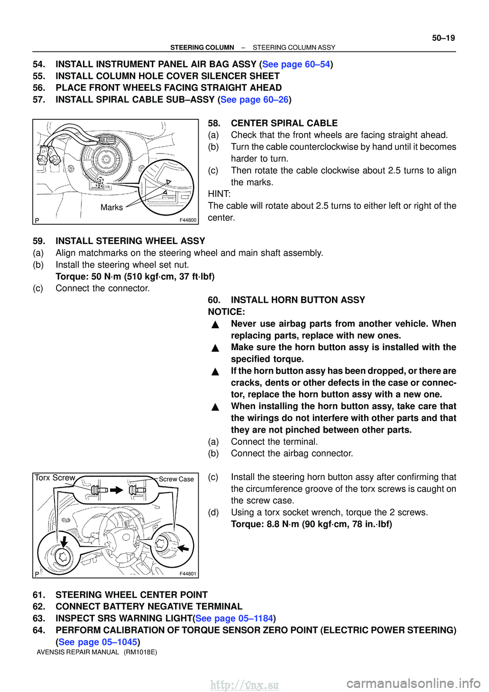
58. CENTER SPIRAL CABLE
(a) Check that the front wheels are facing straight ahead.
(b) Turn the cable counterclockwise by hand until it becomesharder to turn.
(c) Then rotate the cable clockwise about 2.5 turns to align the marks.
HINT:
The cable will rotate about 2.5 turns to either left or right of the
center.
59. INSTALL STEERING WHEEL ASSY
(a) Align matchmarks on the steering wheel and main shaft assembly.
(b) Install the steering wheel set nut. Torque: 50 N´m (510 kgf´cm, 37 ft´lbf)
(c) Connect the connector.
60. INSTALL HORN BUTTON ASSY
NOTICE:
�Never use airbag parts from another vehicle. When
replacing parts, replace with new ones.
�Make sure the horn button assy is installed with the
specified torque.
�If the horn button assy has been dropped, or there are
cracks, dents or other defects in the case or connec-
tor, replace the horn button assy with a new one.
�When installing the horn button assy, take care that
the wirings do not interfere with other parts and that
they are not pinched between other parts.
(a) Connect the terminal.
(b) Connect the airbag connector.
(c) Install the steering horn button assy after confirming that the circumference groove of the torx screws is caught on
the screw case.
(d) Using a torx socket wrench, torque the 2 screws. Torque: 8.8 N´m (90 kgf´cm, 78 in.´lbf)
61. STEERING WHEEL CENTER POINT
62. CONNECT BATTERY NEGATIVE TERMINAL
63.INSPECT SRS WARNING LIGHT(See page 05±1184)
64. PERFORM CALIBRATION OF TORQUE SENSOR ZERO POINT (ELECTRIC POWER STEERING) (See page 05±1045)
http://vnx.su
Page 1444 of 2234
H42637
H42638Marks
±
SUPPLEMENTAL RESTRAINT SYSTEM SPIRAL CABLE SUB±ASSY
60±27
AVENSIS REPAIR MANUAL (RM1018E)
13. INSTALL SPIRAL CABLE SUB±ASSY
(a) Set the turn signal switch to the neutral position.
NOTICE:
Make sure of the neutral position since the pin of the turn signal switc\
h may be snapped.
(b) Install the spiral cable sub±assy.
NOTICE:
When replacing the spiral cable sub±assy with a new one, remove the l\
ock pin before installing the
steering wheel assy.
(c) Connect the airbag connector and the connector.
(d) Install the steering column cover with the 3 screws.
14. ADJUST SPIRAL CABLE SUB±ASSY
(a) Check that the ignition switch is off.
(b) Check that the battery negative terminal is disconnected.
NOTICE:
Do not start the operation for 90 seconds after removing
the terminal.
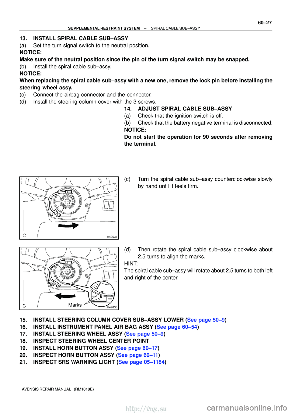
(c) Turn the spiral cable sub±assy counterclockwise slowlyby hand until it feels firm.
(d) Then rotate the spiral cable sub±assy clockwise about 2.5 turns to align the marks.
HINT:
The spiral cable sub±assy will rotate about 2.5 turns to both left
and right of the center.
15.INSTALL STEERING COLUMN COVER SUB±ASSY LOWER (See page 50±9)
16.INSTALL INSTRUMENT PANEL AIR BAG ASSY (See page 60±54)
17.INSTALL STEERING WHEEL ASSY (See page 50±9)
18. INSPECT STEERING WHEEL CENTER POINT
19.INSTALL HORN BUTTON ASSY (See page 60±17)
20.INSPECT HORN BUTTON ASSY (See page 60±11)
21.INSPECT SRS WARNING LIGHT (See page 05±1184)
http://vnx.su
Page 1446 of 2234
60±2
±
SUPPLEMENTAL RESTRAINT SYSTEM SUPPLEMENTAL RESTRAINT SYSTEM
AVENSIS REPAIR MANUAL (RM1018E)
�When the negative (±) terminal cable is disconnected from the batte\
ry, the memory of the clock
and audio system will be canceled. So before starting work, make a record o\
f the contents mem-
orized in the audio memory system. When work is finished, reset the audio syst\
ems as they
were before and adjust the clock. To avoid erasing the memory in each memory system, never
use a back±up power supply from outside the vehicle.
�If the vehicle is equipped with a mobile communication system, refer to the precaution in the
INTRODUCTION section.
http://vnx.su