2003 SSANGYONG MUSSO transmission
[x] Cancel search: transmissionPage 1124 of 1574
TRANSFER CASE (TOD) 5D2-35
Removal & Installation Procedure1. Disconnect (-) cable from battery.
2. Lift on vehicle and make sure on safety. NoticeBe careful for catalytic converter due to high temperature after driving or engine running.
3. Prepare a vessel to drain transfer case and manual transmission oil.
4. Release drain plug and drain transfer case and manual transmission oil. If planar damper is installed, unscrew 4 bolts and remove
the planar damper. NoticeOil drain should be along with whole transfer case
disassembly and assembly.
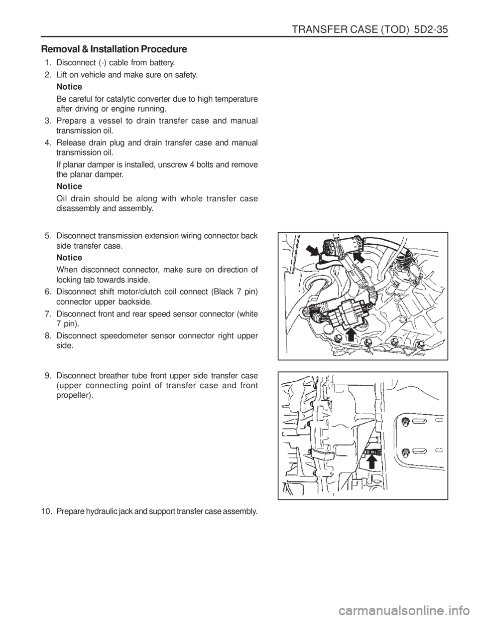
5. Disconnect transmission extension wiring connector back
side transfer case. Notice
When disconnect connector, make sure on direction of locking tab towards inside.
6. Disconnect shift motor/clutch coil connect (Black 7 pin) connector upper backside.
7. Disconnect front and rear speed sensor connector (white 7 pin).
8. Disconnect speedometer sensor connector right upper side.
9. Disconnect breather tube front upper side transfer case (upper connecting point of transfer case and front propeller).
10. Prepare hydraulic jack and support transfer case assembly.
Page 1125 of 1574
5D2-36 TRANSFER CASE (TOD)
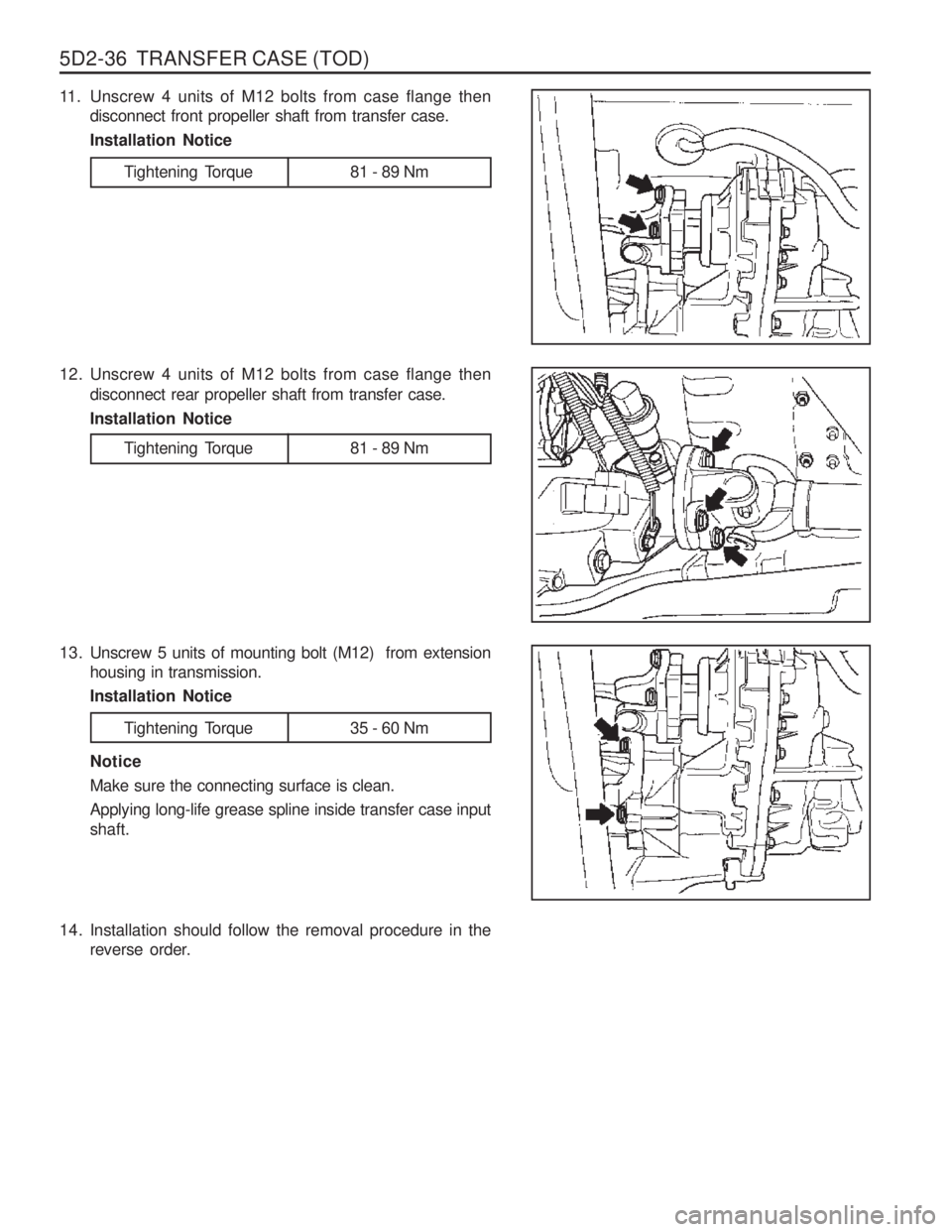
11. Unscrew 4 units of M12 bolts from case flange thendisconnect front propeller shaft from transfer case. Installation Notice
Tightening Torque 81 - 89 Nm
12. Unscrew 4 units of M12 bolts from case flange then disconnect rear propeller shaft from transfer case. Installation Notice
13. Unscrew 5 units of mounting bolt (M12) from extension housing in transmission.Installation Notice
Tightening Torque 81 - 89 Nm
Tightening Torque 35 - 60 Nm
Notice Make sure the connecting surface is clean.Applying long-life grease spline inside transfer case input shaft.
14. Installation should follow the removal procedure in the reverse order.
Page 1136 of 1574
TRANSFER CASE (TOD) 5D2-47
Assembly Procedure Assembly
Before assembly, lubricate all parts with Automatic Transmission Fluid or equivalent.
1. If removed, drive the bearing into the front output case bore.Drive the bearing in staight, making sure it is not cocked in the bore. Install the internal snap ring that retains the bearing to the front case.
2. If removed, install the front yoke to flange seal in the front case bore.
3. If removed, install the yoke to flange seal into the mounting adapter bore.
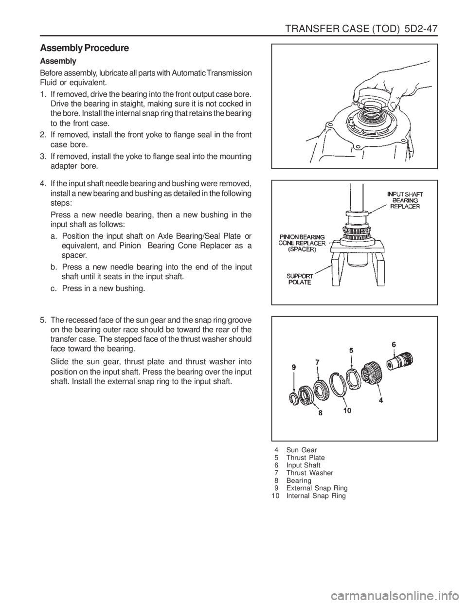
4 Sun Gear
5 Thrust Plate
6 Input Shaft
7 Thrust Washer
8 Bearing
9 External Snap Ring
10 Internal Snap Ring
4. If the input shaft needle bearing and bushing were removed,
install a new bearing and bushing as detailed in the following steps: Press a new needle bearing, then a new bushing in the input shaft as follows:
a. Position the input shaft on Axle Bearing/Seal Plate or equivalent, and Pinion Bearing Cone Replacer as a
spacer.
b. Press a new needle bearing into the end of the input shaft until it seats in the input shaft.
c. Press in a new bushing.
5. The recessed face of the sun gear and the snap ring groove on the bearing outer race should be toward the rear of thetransfer case. The stepped face of the thrust washer shouldface toward the bearing.
Slide the sun gear, thr ust plate and thrust washer into
position on the input shaft. Press the bearing over the input shaft. Install the external snap ring to the input shaft.
Page 1137 of 1574
5D2-48 TRANSFER CASE (TOD)
6. Install the front planet to the sun gear and input shaft.Install the internal snap ring to the planetary carrier.
7. Place the tanged snap ring in the case. Expand snap ring with snap ring pliers and install planetary carrier assembly. Check installation by holding the case and carefully tappingthe face of the input shaft against a wooden block to makesure the snap ring is installed.
8. Remove all traces of gasket sealant from the front case and mounting adapter mating surfaces. Install a bead ofgasket sealant on the surface of the front case.
9. Install the high-low shift fork and high-low collar as an assembly into the front planet. Notice Make sure that the nylon wear pads are installed on the shift fork and snapped securely into place.
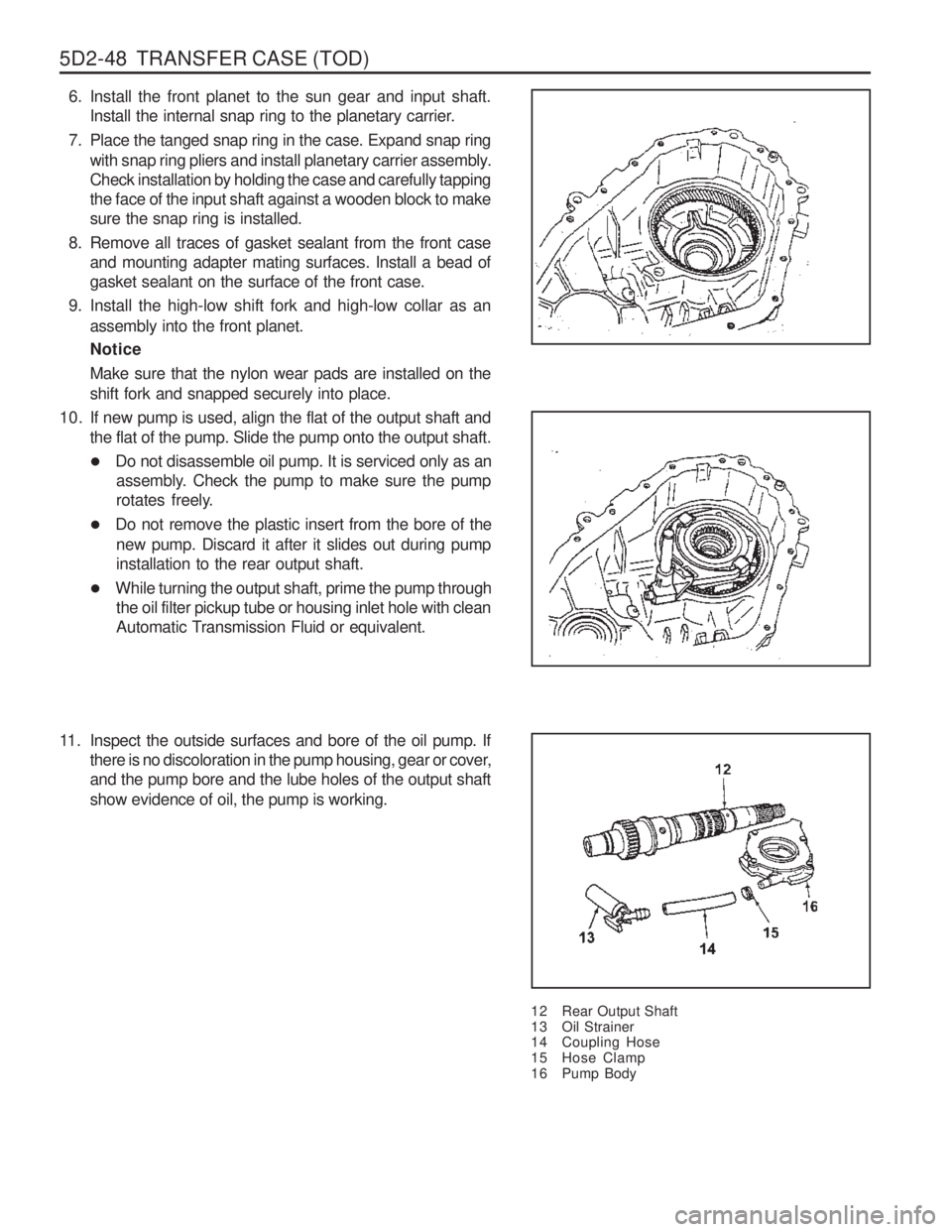
12 Rear Output Shaft
13 Oil Strainer
14 Coupling Hose
15 Hose Clamp
16 Pump Body
10. If new pump is used, align the flat of the output shaft and
the flat of the pump. Slide the pump onto the output shaft.
�Do not disassemble oil pump. It is serviced only as an
assembly. Check the pump to make sure the pump
rotates freely.
� Do not remove the plastic insert from the bore of the
new pump. Discard it after it slides out during pumpinstallation to the rear output shaft.
� While turning the output shaft, prime the pump through
the oil filter pickup tube or housing inlet hole with clean
Automatic Transmission Fluid or equivalent.
11. Inspect the outside surfaces and bore of the oil pump. If there is no discoloration in the pump housing, gear or cover,and the pump bore and the lube holes of the output shaft show evidence of oil, the pump is working.
Page 1142 of 1574
TRANSFER CASE (TOD) 5D2-53
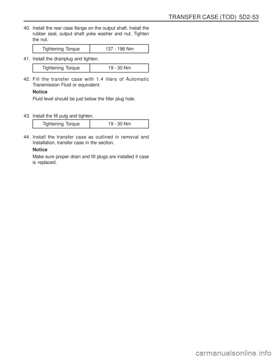
40. Install the rear case flange on the output shaft. Install therubber seal, output shaft yoke washer and nut. Tighten the nut.
Tightening Torque 137 - 196 Nm
41. Install the drainplug and tighten.
42. Fill the transfer case with 1.4 liters of Automatic Transmission Fluid or equivalent. NoticeFluid level should be just below the filler plug hole.
Tightening Torque 19 - 30 Nm
Tightening Torque 19 - 30 Nm
43. Install the fill pulg and tighten.
44. Install the transfer case as outlined in removal and
Installation, transfer case in the section. NoticeMake sure proper drain and fill plugs are installed if case is replaced.
Page 1203 of 1574
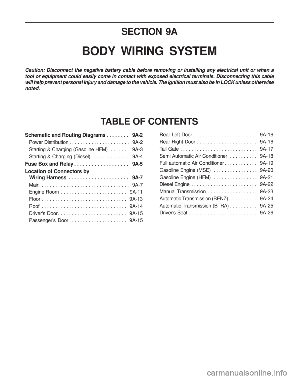
SECTION 9A
BODY WIRING SYSTEM
Schematic and Routing Diagrams . . . . . . . . 9A-2
Power Distribution . . . . . . . . . . . . . . . . . . . . . . 9A-2
Starting & Charging (Gasoline HFM) . . . . . . . 9A-3
Starting & Charging (Diesel) . . . . . . . . . . . . . . 9A-4
Fuse Box and Relay . . . . . . . . . . . . . . . . . . . 9A-5
Location of Connectors by
Wiring Harness . . . . . . . . . . . . . . . . . . . . . 9A-7
Main . . . . . . . . . . . . . . . . . . . . . . . . . . . . . . . . 9A-7
Engine Room . . . . . . . . . . . . . . . . . . . . . . . . 9A-11
Floor . . . . . . . . . . . . . . . . . . . . . . . . . . . . . . . 9A-13
Roof . . . . . . . . . . . . . . . . . . . . . . . . . . . . . . . 9A-14
Driver's Door . . . . . . . . . . . . . . . . . . . . . . . . . 9A-15
Passenger's Door . . . . . . . . . . . . . . . . . . . . . 9A-15
TABLE OF CONTENTS
Caution: Disconnect the negative battery cable before removing or installing any electrical unit or when a tool or equipment could easily come in contact with exposed electrical terminals. Disconnecting this cable will help prevent personal injury and damage to the vehicle. The ignition must also be in LOCK unless otherwisenoted.
Rear Left Door . . . . . . . . . . . . . . . . . . . . . . . 9A-16
Rear Right Door . . . . . . . . . . . . . . . . . . . . . . 9A-16
Tail Gate . . . . . . . . . . . . . . . . . . . . . . . . . . . . 9A-17
Semi Automatic Air Conditioner . . . . . . . . . . 9A-18
Full automatic Air Conditioner . . . . . . . . . . . . 9A-19
Gasoline Engine (MSE) . . . . . . . . . . . . . . . . 9A-20
Gasoline Engine (HFM) . . . . . . . . . . . . . . . . 9A-21
Diesel Engine . . . . . . . . . . . . . . . . . . . . . . . . 9A-22
Manual Transmission . . . . . . . . . . . . . . . . . . 9A-23
Automatic Transmission (BENZ) . . . . . . . . . . 9A-24
Automatic Transmission (BTRA) . . . . . . . . . . 9A-25
Driver's Seat . . . . . . . . . . . . . . . . . . . . . . . . . 9A-26
Page 1210 of 1574
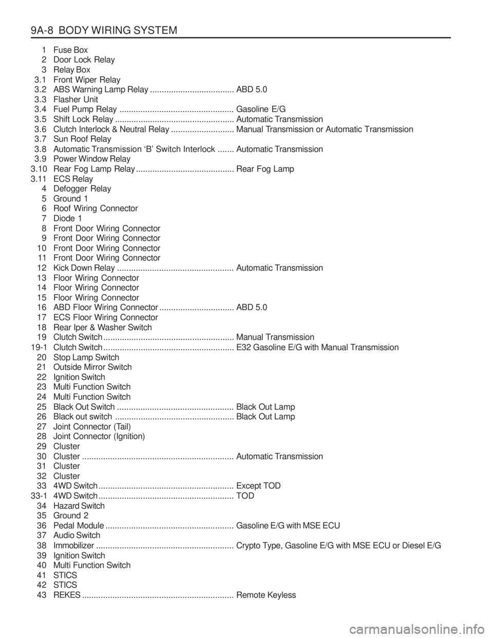
9A-8 BODY WIRING SYSTEM1 Fuse Box
2 Door Lock Relay
3 Relay Box
3.1 Front Wiper Relay
3.2 ABS Warning Lamp Relay ....................................ABD 5.0
3.3 Flasher Unit
3.4 Fuel Pump Relay ................................................. Gasoline E/G
3.5 Shift Lock Relay ................................................... Automatic Transmission
3.6 Clutch Interlock & Neutral Relay ...........................Manual Transmission or Automatic Transmission
3.7 Sun Roof Relay
3.8 Automatic T ransmission ‘B’ Switch Interlock ....... Automatic Transmission
3.9 Power Window Relay
3.10 Rear Fog Lamp Relay .......................................... Rear Fog Lamp
3.11 ECS Relay 4 Defogger Relay
5 Ground 1
6 Roof Wiring Connector
7 Diode 1
8 Front Door Wiring Connector
9 Front Door Wiring Connector
10 Front Door Wiring Connector 11 Front Door Wiring Connector
12 Kick Down Relay .................................................. Automatic Transmission
13 Floor Wiring Connector
14 Floor Wiring Connector
15 Floor Wiring Connector
16 ABD Floor Wiring Connector ................................ABD 5.0
17 ECS Floor Wiring Connector
18 Rear Iper & Washer Switch
19 Clutch Switch ........................................................ Manual Transmission
19-1 Clutch Switch ........................................................ E32 Gasoline E/G with Manual Transmission
20 Stop Lamp Switch
21 Outside Mirror Switch
22 Ignition Switch
23 Multi Function Switch
24 Multi Function Switch
25 Black Out Switch .................................................. Black Out Lamp
26 Black out switch ................................................... Black Out Lamp
27 Joint Connector (Tail)
28 Joint Connector (Ignition)
29 Cluster
30 Cluster ................................................................. Automatic Transmission
31 Cluster
32 Cluster
33 4WD Switch .......................................................... Except TOD
33-1 4WD Switch .......................................................... TOD
3 4 Hazard Switch
35 Ground 2
36 Pedal Module ....................................................... Gasoline E/G with MSE ECU
37 Audio Switch
3 8 Immobilizer ........................................................... Crypto Type, Gasoline E/G with MSE ECU or Diesel E/G
39 Ignition Switch
40 Multi Function Switch
4 1 STICS
4 2 STICS
4 3 REKES ................................................................. Remote Keyless
Page 1211 of 1574
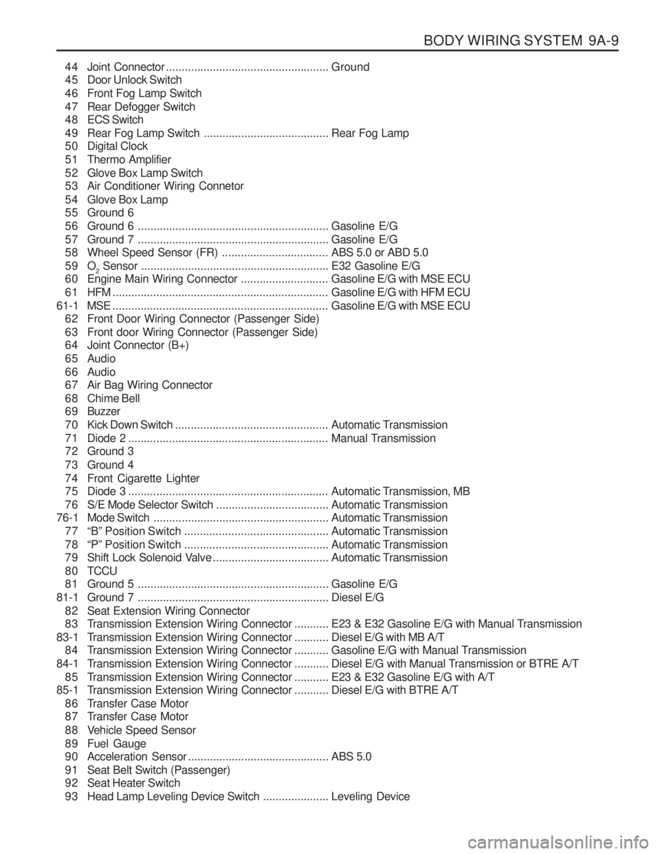
BODY WIRING SYSTEM 9A-9
44 Joint Connector.................................................... Ground
45 Door Unlock Switch
46 Front Fog Lamp Switch
47 Rear Defogger Switch
4 8 ECS Switch
49 Rear Fog Lamp Switch ........................................Rear Fog Lamp
50 Digital Clock
51 Thermo Amplifier
52 Glove Box Lamp Switch
53 Air Conditioner Wiring Connetor
54 Glove Box Lamp
55 Ground 6
56 Ground 6 ............................................................. Gasoline E/G
57 Ground 7 ............................................................. Gasoline E/G
58 Wheel Speed Sensor (FR) ..................................ABS 5.0 or ABD 5.0
59 O 2 Sensor
............................................................ E32 Gasoline E/G
60 Engine Main Wiring Connector ............................Gasoline E/G with MSE ECU
61 HFM ..................................................................... Gasoline E/G with HFM ECU
61-1 MSE ..................................................................... Gasoline E/G with MSE ECU
62 Front Door Wiring Connector (Passenger Side)
63 Front door Wiring Connector (Passenger Side)
64 Joint Connector (B+)
65 Audio
66 Audio
67 Air Bag Wiring Connector
68 Chime Bell
6 9 Buzzer
70 Kick Down Switch ................................................. Automatic Transmission
71 Diode 2 ................................................................ Manual Transmission
72 Ground 3
73 Ground 4
74 Front Cigarette Lighter
75 Diode 3 ................................................................ Automatic Transmission, MB
76 S/E Mode Selector Switch ....................................Automatic Transmission
76-1 Mode Switch ........................................................ Automatic Transmission
77 “B” Position Switch .............................................. Automatic Transmission
78 “P” Position Switch .............................................. Automatic Transmission
79 Shift Lock Solenoid Valve .....................................Automatic Transmission
8 0 TCCU
81 Ground 5 ............................................................. Gasoline E/G
81-1 Ground 7 ............................................................. Diesel E/G
82 Seat Extension Wiring Connector
83 Transmission Extension Wiring Connector ...........E23 & E32 Gasoline E/G with Manual Transmission
83-1 T ransmission Extension Wiring Connector ...........Diesel E/G with MB A/T
84 Transmission Extension Wiring Connector ...........Gasoline E/G with Manual Transmission
84-1 T ransmission Extension Wiring Connector ...........Diesel E/G with Manual Transmission or BTRE A/T
85 Transmission Extension Wiring Connector ...........E23 & E32 Gasoline E/G with A/T
85-1 T ransmission Extension Wiring Connector ...........Diesel E/G with BTRE A/T
86 Transfer Case Motor
87 Transfer Case Motor
88 Vehicle Speed Sensor
89 Fuel Gauge
90 Acceleration Sensor ............................................. ABS 5.0
91 Seat Belt Switch (Passenger)
92 Seat Heater Switch
93 Head Lamp Leveling Device Switch .....................Leveling Device