Page 170 of 1574
1B2-18 M161 ENGINE MECHANICAL Operation at Idling and Mid-Load
�The throttle valve(6) is closed or very partially opened, and the vacuum pressure in intake manifold is high. The blow-by gas and the fresh air that is additionally supplied through the vent connection(D) in the crankcase in partialload gets supplied to the combustion chamber from the crank
chamber(12) through the oil separation chamber(11), air- conditioner bracket(10), vent line(9), and restrictor(7)mounted to the cylinder head. The circulated engine oil returns to the oil pan through the oil return pipe(13) at the bottom of oil separation
chamber(11). The fresh air gets supplied to the crank chamber(12) through the HFM sensor(1), intake air duct(4), vent line(5), oil separation chamber(3), chain housing(17), and the timing gear case cover(15). The additional supply of the fresh air is needed to prevent from forming the residues of the engine oil.
Page 171 of 1574
M161 ENGINE MECHANICAL 1B2-19
Operation When Full-Load at Partial Load
1 HFM Sensor
2 Cylinder Head Cover
3 Oil Spearation Chamber (Full-Load or OverMid-Load)
4 Intake Air Duct (Cross Pipe)
5 Vent Line (Full-Load or Over Mid-Load)
6 Throttle Valve
7 Restrictor, Diameter 1.1mm (Mid-Load at Idling)
8 Intake Manifold
9 Vent Line (Mid-Load at Idling)
10 Air Conditioner Bracket 11 Oil Separation Chamber (Mid-Load at Idling)
12 Crank Chamber
13 Oil Return Pipe
14 Oil Pan
15 Timing Gear Case Cover
16 Crankcase
17 Chain Housing
A Fresh Air
C Blow-by Gas
D Vent Connection
Page 266 of 1574

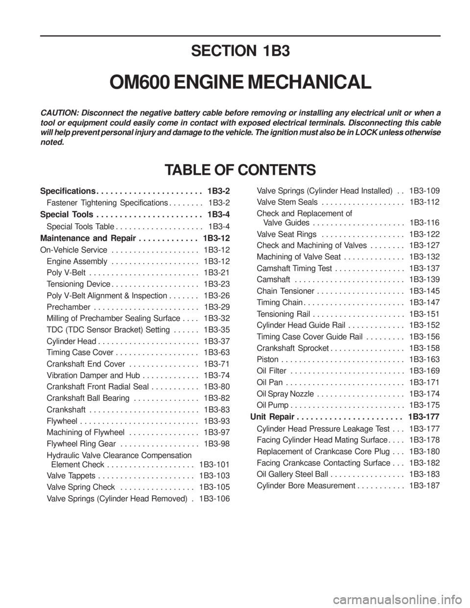
SECTION 1B3
OM600 ENGINE MECHANICAL
CAUTION: Disconnect the negative battery cable before removing or installing any electrical unit or when a tool or equipment could easily come in contact with exposed electrical terminals. Disconnecting this cable will help prevent personal injury and damage to the vehicle. The ignition must also be in LOCK unless otherwisenoted.
Specifications . . . . . . . . . . . . . . . . . . . . . . . 1B3-2Fastener Tightening Specifications . . . . . . . . 1B3-2
Special Tools . . . . . . . . . . . . . . . . . . . . . . . 1B3-4 Special Tools Table . . . . . . . . . . . . . . . . . . . . 1B3-4
Maintenance and Repair . . . . . . . . . . . . . 1B3-12
On-Vehicle Service . . . . . . . . . . . . . . . . . . . . 1B3-12
Engine Assembly . . . . . . . . . . . . . . . . . . . . 1B3-12
Poly V-Belt . . . . . . . . . . . . . . . . . . . . . . . . . 1B3-21
Tensioning Device . . . . . . . . . . . . . . . . . . . . 1B3-23
Poly V-Belt Alignment & Inspection . . . . . . . 1B3-26
Prechamber . . . . . . . . . . . . . . . . . . . . . . . . 1B3-29
Milling of Prechamber Sealing Surface . . . . 1B3-32
TDC (TDC Sensor Bracket) Setting . . . . . . 1B3-35
Cylinder Head . . . . . . . . . . . . . . . . . . . . . . . 1B3-37
Timing Case Cover . . . . . . . . . . . . . . . . . . . 1B3-63
Crankshaft End Cover . . . . . . . . . . . . . . . . 1B3-71
Vibration Damper and Hub . . . . . . . . . . . . . 1B3-74
Crankshaft Front Radial Seal . . . . . . . . . . . 1B3-80
Crankshaft Ball Bearing . . . . . . . . . . . . . . . 1B3-82
Crankshaft . . . . . . . . . . . . . . . . . . . . . . . . . 1B3-83
Flywheel . . . . . . . . . . . . . . . . . . . . . . . . . . . 1B3-93
Machining of Flywheel . . . . . . . . . . . . . . . . 1B3-97
Flywheel Ring Gear . . . . . . . . . . . . . . . . . . 1B3-98
Hydraulic Valve Clearance Compensation
Element Check . . . . . . . . . . . . . . . . . . . . 1B3-101
Valve Tappets . . . . . . . . . . . . . . . . . . . . . . 1B3-103
Valve Spring Check . . . . . . . . . . . . . . . . . 1B3-105
Valve Springs (Cylinder Head Removed) . 1B3-106
TABLE OF CONTENTS
Valve Springs (Cylinder Head Installed) . . 1B3-109
Valve Stem Seals . . . . . . . . . . . . . . . . . . . 1B3-112
Check and Replacement of Valve Guides . . . . . . . . . . . . . . . . . . . . . 1B3-116
Valve Seat Rings . . . . . . . . . . . . . . . . . . . 1B3-122
Check and Machining of Valves . . . . . . . . 1B3-127
Machining of Valve Seat . . . . . . . . . . . . . . 1B3-132
Camshaft Timing Test . . . . . . . . . . . . . . . . 1B3-137
Camshaft . . . . . . . . . . . . . . . . . . . . . . . . . 1B3-139
Chain Tensioner . . . . . . . . . . . . . . . . . . . . 1B3-145
Timing Chain . . . . . . . . . . . . . . . . . . . . . . . 1B3-147
Tensioning Rail . . . . . . . . . . . . . . . . . . . . . 1B3-151
Cylinder Head Guide Rail . . . . . . . . . . . . . 1B3-152
Timing Case Cover Guide Rail . . . . . . . . . 1B3-156
Crankshaft Sprocket . . . . . . . . . . . . . . . . . 1B3-158
Piston . . . . . . . . . . . . . . . . . . . . . . . . . . . . 1B3-163
Oil Filter . . . . . . . . . . . . . . . . . . . . . . . . . . 1B3-169
Oil Pan . . . . . . . . . . . . . . . . . . . . . . . . . . . 1B3-171
Oil Spray Nozzle . . . . . . . . . . . . . . . . . . . . 1B3-174
Oil Pump . . . . . . . . . . . . . . . . . . . . . . . . . . 1B3-175
Unit Repair . . . . . . . . . . . . . . . . . . . . . . . 1B3-177
Cylinder Head Pressure Leakage Test . . . 1B3-177
Facing Cylinder Head Mating Surface . . . . 1B3-178
Replacement of Crankcase Core Plug . . . 1B3-180
Facing Crankcase Contacting Surface . . . 1B3-182
Oil Gallery Steel Ball . . . . . . . . . . . . . . . . . 1B3-183
Cylinder Bore Measurement . . . . . . . . . . . 1B3-187
Page 270 of 1574
OM600 ENGINE MECHANICAL 1B3-5
116 589 03 07 00
T Type Socket Wrench
601 589 00 25 00
SPECIAL TOOLS TABLE (Co n t
’d)115 589 34 63 00
601 589 00 10 00
Cylinder Head Bolt 102
102 589 12 15 00(
��
��
�17) Drift 102 589 00 15 00
(
��
��
�34) Drift
617 589 10 21 00
RI Sensor 601 589 05 14 00
Assembly Cage
Page 276 of 1574
OM600 ENGINE MECHANICAL 1B3-11
000 589 14 21 00Tester
001 589 65 09 00
Serration Wrench 116 589 02 34 00
Thread Bolt
SPECIAL TOOLS TABLE (Co n t
’d)
000 589 00 68 00
Cleaning Set
601 589 05 21 00Looking Screw 617 589 08 21 00 Position Sensor
667 589 04 63 00
Retaining Plate
601 589 00 08 00 Flange
Page 283 of 1574
1B3-18 OM600 ENGINE MECHANICAL
27. Disconnect the preheating time relay sensor plug.
28. Disconnect the coolant temperature sensor plug.
29. Disconnect the accelerator cable from the control linkage.Installation Notice
Tightening Torque 8 - 18 Nm
30. Loosen the connection of control pressure cable (an arrow) used in auto transmission.
Page 300 of 1574
OM600 ENGINE MECHANICAL 1B3-35
TDC (TDC SENSOR BRACKET) SETTING Preceding Work : Removal of No.1 cylinder prechamber
1 Measuring Device
2 Dial Gauge
3 Cylinder Head
4 Piston................................................ Set at TDC
Tools Service 001 589 32 21 00 Dial Gauge601 589 07 21 00 Deqth Gauge667 589 01 21 00 Fixing Device Notice
� The TDC sensor bra cket must be adjusted in case of
followings.
� When replacing the TDC sensor bracket.
� When replacing the crankshaft, the hub or the vibration
damper.
� When replacing or installing the timing case cover.
� After engine overhauling.
� If the cylinder head is removed, the measuring pin of the dial gauge can be positioned on the piston crown. This is done by placing the magnetic dial holder on the mating surface of the crankcase.
Page 301 of 1574

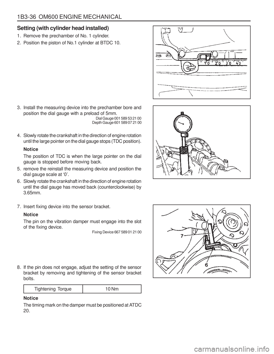
1B3-36 OM600 ENGINE MECHANICAL Setting (with cylinder head installed)
1. Remove the prechamber of No. 1 cylinder.
2. Position the piston of No.1 cylinder at BTDC 10.
3. Install the measuring device into the prechamber bore andposition the dial gauge with a preload of 5mm. Dial Gauge 001 589 53 21 00
Depth Gauge 601 589 07 21 00
4. Slowly rotate the crankshaft in the direction of engine rotation until the large pointer on the dial gauge stops (TDC position). Notice The position of TDC is when the large pointer on the dial gauge is stopped before moving back.
5. remove the reinstall the measuring device and position the dial gauge scale at ‘0’.
6. Slowly rotate the crankshaft in the direction of engine rotation until the dial gauge has moved back (counterclockwise) by3.65mm.
7. Insert fixing device into the sensor bracket. Notice The pin on the vibration damper must engage into the slot of the fixing device. Fixing Device 667 589 01 21 00
8. If the pin does not engage, adjust the setting of the sensor bracket by removing and tightening of the sensor bracketbolts.
Tightening Torque 10 Nm
Notice
The timing mark on the damper must be positioned at ATDC 20.