Page 607 of 1574
M162 ENGINE CONTROLS 1F1-75
COOLANT TEMPERATURE SENSOR
1 Artificial Resin Housing
2 Metal Housing
3 NTC (negative temperature coefficient) Resistor
Removal & Installation Procedure
1. Remove the pressure by opening the pressure cap in the coolant subtank.
2. Disconnect the connector and remove the coolant temperature sensor. Installation Notice Replace the seals with new one.
3. Installation should follow the removal procedure in the reverse order.
4. Check for leaks at each connections after starting the engine. 4 Connector
5 Coolant Temperature Sensor
Tightening Torque 18 - 22 Nm
Page 608 of 1574
1F1-76 M162 ENGINE CONTROLS 2. Measure the resistance between the coolant temperaturesensor terminal No.1 and No.4 with the coolant temperature sensor disconnected.
Inspection 1. Measure the coolant sensor input voltage between the ECU
terminal No.79 and No.78 while the ignition switch in "ON" position. Notice Replace wiring and coolant temperature sensor if out of specified value. allowable error :
±5%
allowable error : ±5%
Voltage (V)
3.57 1.220.78
Temperature (
°C)
203040
Resistance (W) 2,500322 185
Temperature (
°C)
203040
Page 609 of 1574
M162 ENGINE CONTROLS 1F1-77
Service Data Resistance characteristic curve according to the coolant temperatureTemperature(
°C) Resistance(W) Voltage(V) Temperature( °C) Resistance(W) Voltage(V)
-40 48,550 4.8991 60 594 1.8632
-30 27,000 4.8214 70 434 1.5132
-20 15,670 4.7001 80 322 1.2179
-10 9,450 4.5215 90 243 0.9775 0 5,890 4.4273 100 185 0.7806
10 3,790 3.9562 110 143 0.6255
20 2,500 3.5714 120 111.6 0.5020
30 1,692 3.1426 130 88.0 0.4044
40 1,170 2.6959 140 71.2 0.3323 50 826 2.2618 - - -
Page 618 of 1574
OM600 ENGINE CONTROLS 1F3-7
Vacuum 500 mbar
Lines and connections leaking. Faulty PLA vacuum unit.
Test step 1
Connect vacuum pump (14) with Y adapter to PLA vacuum unit (5). Run engine at idle speed.YES NO
(Remove the connection hose from vacuum pump)
Connect vacuum pump (14) direct to PLA vacuum unit(5) and pressurize with vacuum.
Vacuum is built up and idle speed increases approx. 150-200 rpm
YES NO
Faulty PLA vacuum unit
(Coolant Temperature 30 °C)
Stop the engine Seal the air admission line with plug. Connect the vacuum pump to line to thermovalve andpressurize the line with vacuum.
Vacuum is built up.
YES NO
Lines and connectors leaking. Faulty thermovalve.
=
>
Page 626 of 1574
1F3-16 OM600 ENGINE CONTROLSIdle Speed
750 - 850 rpm 720 - 820 rpm
EngineOM661LA EngineOM662LA Engine
Tools Required 667 589 00 21 00 TDC Pulse Generato
Commercial Tool
IDLE SPEED ADJUSTMENT Service Data
e.g. Bosch, MOT 001.03
Sun, DIT 9000
Digital Tester
Adjustment Procedure
1. Connect the digital tester (1) and TDC pulse sender unit
(11).
2. Run the engine and warm up the coolant to 60~80 °C.
TDC pulse generator 667 589 02 21 00
3. Disconnect the vacuum hose (4) from the PLA unit to check idle speed with tester.
4. Check idle speed with tester.
Notice
To adjust idle speed, loosen the locking nut (6) of PLA unit.
OM 661LA Engine 750 - 850rpm
OM 662LA Engine
720 - 820rpm
Page 1173 of 1574

FATC-HAVC 7D-17
7b7a
Water sensor connector
3
�
0.5RB
Airconditioner control unit connector
V
5
�
0.5BL
Water Sensor
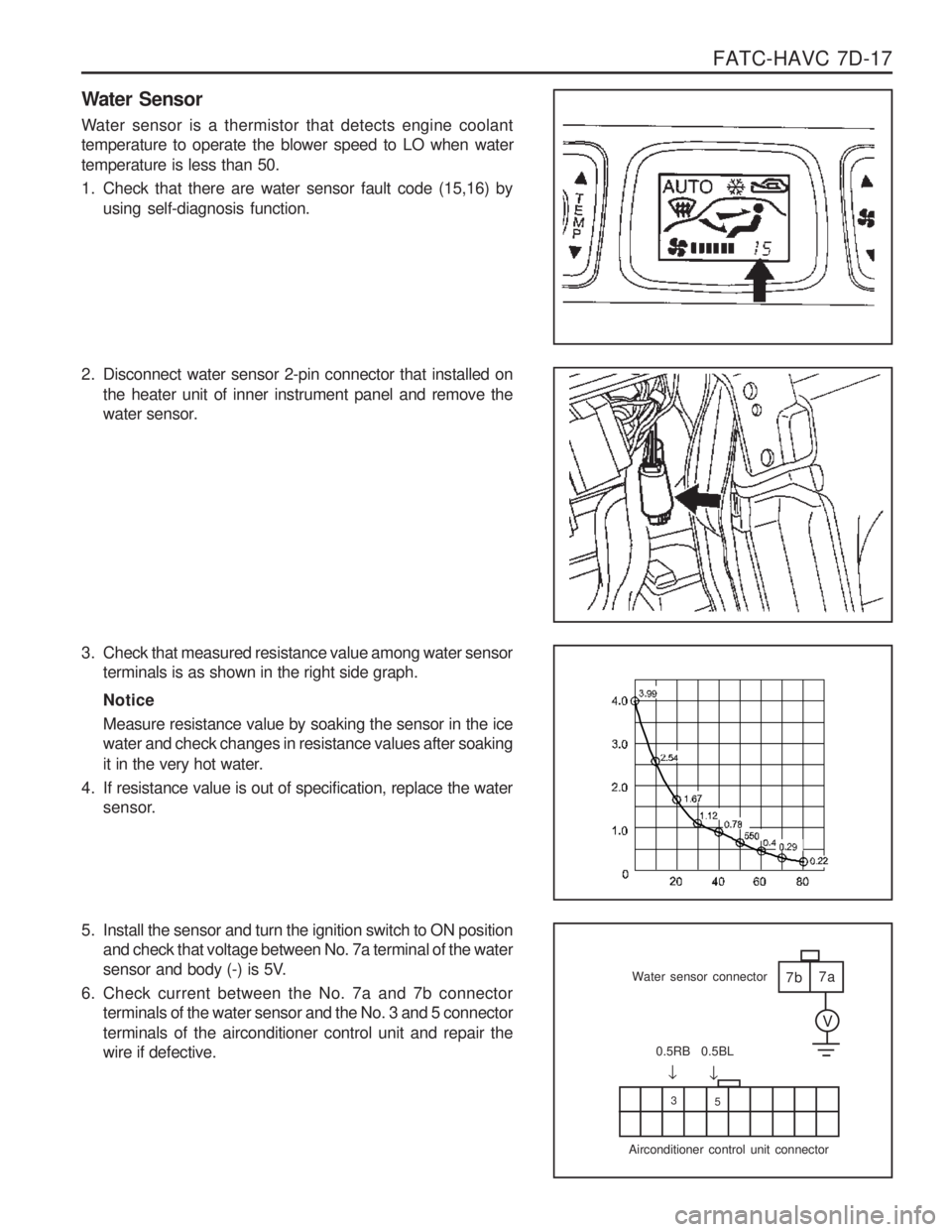
Water sensor is a thermistor that detects engine coolant temperature to operate the blower speed to LO when water temperature is less than 50.
1. Check that there are water sensor fault code (15,16) by
using self-diagnosis function.
3. Check that measured resistance value among water sensor terminals is as shown in the right side graph. Notice Measure resistance value by soaking the sensor in the ice water and check changes in resistance values after soaking
it in the very hot water.
4. If resistance value is out of specification, replace the water sensor.
5. Install the sensor and turn the ignition switch to ON position and check that voltage between No. 7a terminal of the water
sensor and body (-) is 5V.
6. Check current between the No. 7a and 7b connector terminals of the water sensor and the No. 3 and 5 connector terminals of the airconditioner control unit and repair the wire if defective.
2. Disconnect water sensor 2-pin connector that installed on
the heater unit of inner instrument panel and remove the
water sensor.
Page 1252 of 1574
INSTRUMENTATION/DRIVER INFORMATION 9E-3
COMBINATION METER
COMPONENT LOCATOR
1. Speedometer
2. Odometer
3. Trip odometer
4. Tachometer
5. Coolant temperature gauge
6. Fuel gauge
7. Low fuel level warning light
8. Turn signal indicator (left)
9. Turn signal indicator (right)
10. Outside rearview mirror & tailgate heating switch
11. Reset button
12. Auto shift indicator*
13. Door open warning light
14. TCS indicator (equipped with ABD)*
21. ABS warning light* 22. EBD warning light*
23. ECS / SPORT warning light*
24. 4 - wheel warning light*
25. 4 - wheel high indicator
26. 4 - wheel low indicator
27. WINTER indicator
28. POWER indicator
29. High beam indicator
15. Alternator warning light
16. Engine oil pressure warning light
17. Brake system warning light
18. Glow indicator light (For Diesel engine)
19. Airbag warning light*
20. Seat belt reminder
Page 1315 of 1574

MUSSO-SPORTS 1A-3
SUPPLEMENT
HUBER EGR
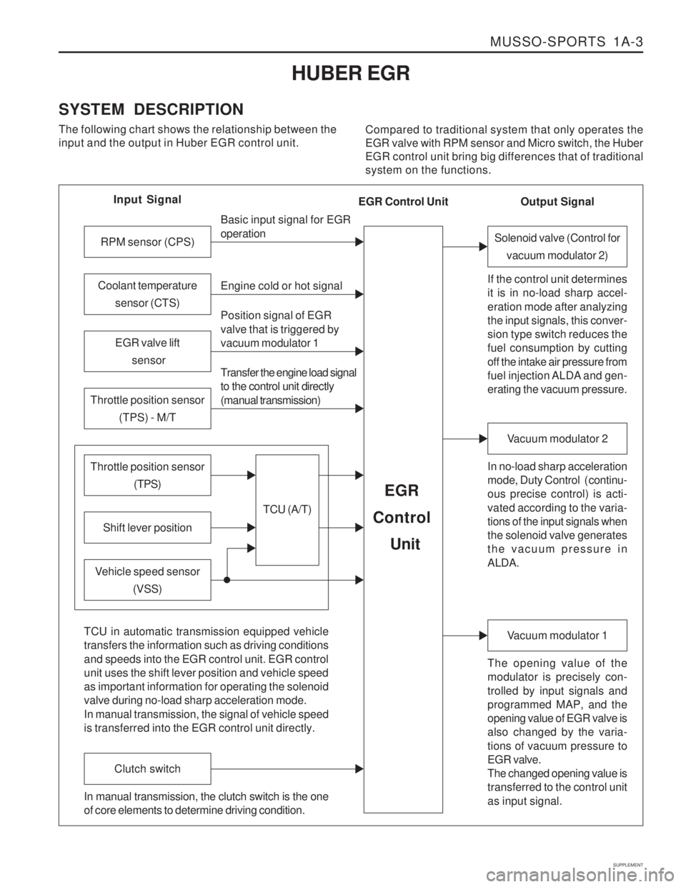
SYSTEM DESCRIPTION The following chart shows the relationship between the input and the output in Huber EGR control unit. Compared to traditional system that only operates theEGR valve with RPM sensor and Micro switch, the HuberEGR control unit bring big differences that of traditionalsystem on the functions.
Input Signal
RPM sensor (CPS)
EGR valve lift sensor
Throttle position sensor (TPS) - M/T
Shift lever position
Throttle position sensor (TPS)
Vehicle speed sensor(VSS) Basic input signal for EGR operation Engine cold or hot signal
Position signal of EGR valve that is triggered by vacuum modulator 1 Transfer the engine load signal to the control unit directly (manual transmission)
TCU (A/T)
EGR
Control
Unit
Coolant temperature sensor (CTS)
Solenoid valve (Control forvacuum modulator 2)
If the control unit determines it is in no-load sharp accel- eration mode after analyzing the input signals, this conver- sion type switch reduces the fuel consumption by cutting off the intake air pressure from
fuel injection ALDA and gen- erating the vacuum pressure. In no-load sharp acceleration
mode, Duty Control ( continu- ous precise control) is acti- vated according to the varia- tions of the input signals when the solenoid valve generates the vacuum pressure in ALDA.
Vacuum modulator 2
The opening value of the modulator is precisely con- trolled by input signals and programmed MAP, and the opening value of EGR valve is also changed by the varia- tions of vacuum pressure to EGR valve. The changed opening value is transferred to the control unit as input signal.
Vacuum modulator 1
TCU in automatic transmission equipped vehicle transfers the information such as driving conditions and speeds into the EGR control unit. EGR control unit uses the shift lever position and vehicle speed as important information for operating the solenoid valve during no-load sharp acceleration mode. In manual transmission, the signal of vehicle speed is transferred into the EGR control unit directly.
Clutch switch
In manual transmission, the clutch switch is the one of core elements to determine driving condition. Output Signal
EGR Control Unit