2003 SSANGYONG MUSSO electric
[x] Cancel search: electricPage 1305 of 1574
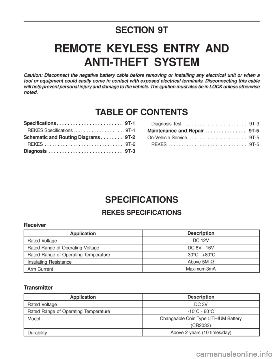
SECTION 9T
REMOTE KEYLESS ENTRY ANDANTI-THEFT SYSTEM
Caution: Disconnect the negative battery cable before removing or installing any electrical unit or when a tool or equipment could easily come in contact with exposed electrical terminals. Disconnecting this cablewill help prevent personal injury and damage to the vehicle. The ignition must also be in LOCK unless otherwisenoted.
TABLE OF CONTENTS
Specifications . . . . . . . . . . . . . . . . . . . . . . . . 9T-1
REKES Specifications . . . . . . . . . . . . . . . . . . . 9T-1
Schematic and Routing Diagrams . . . . . . . . 9T-2
REKES . . . . . . . . . . . . . . . . . . . . . . . . . . . . . . 9T-2
Diagnosis . . . . . . . . . . . . . . . . . . . . . . . . . . . 9T-3
SPECIFICATIONS
REKES SPECIFICATIONS Diagnosis Test . . . . . . . . . . . . . . . . . . . . . . . .
9T-3
Maintenance and Repair . . . . . . . . . . . . . . . 9T-5
On-Vehicle Service . . . . . . . . . . . . . . . . . . . . . . 9T-5
REKES . . . . . . . . . . . . . . . . . . . . . . . . . . . . . . 9T-5
Transmitter
Description DC 3V
-10 °C - 60 °C
Changeable Coin Type LITHIUM Battery (CR2032)
Above 2 years (10 times/day)
Application
Rated Voltage
Rated Range of Operating Temperature Model Durability
Description DC 12V
DC 8V - 16V
-30 °C - +80 °C
Above 5M �
Maximum 3mA
Application
Rated Voltage
Rated Range of Operating Voltage
Rated Range of Operating Temperature Insulating Resistance Arm Current
Receiver
Page 1317 of 1574
MUSSO-SPORTS 1A-5
SUPPLEMENT
KAA5A020
KAA5A020
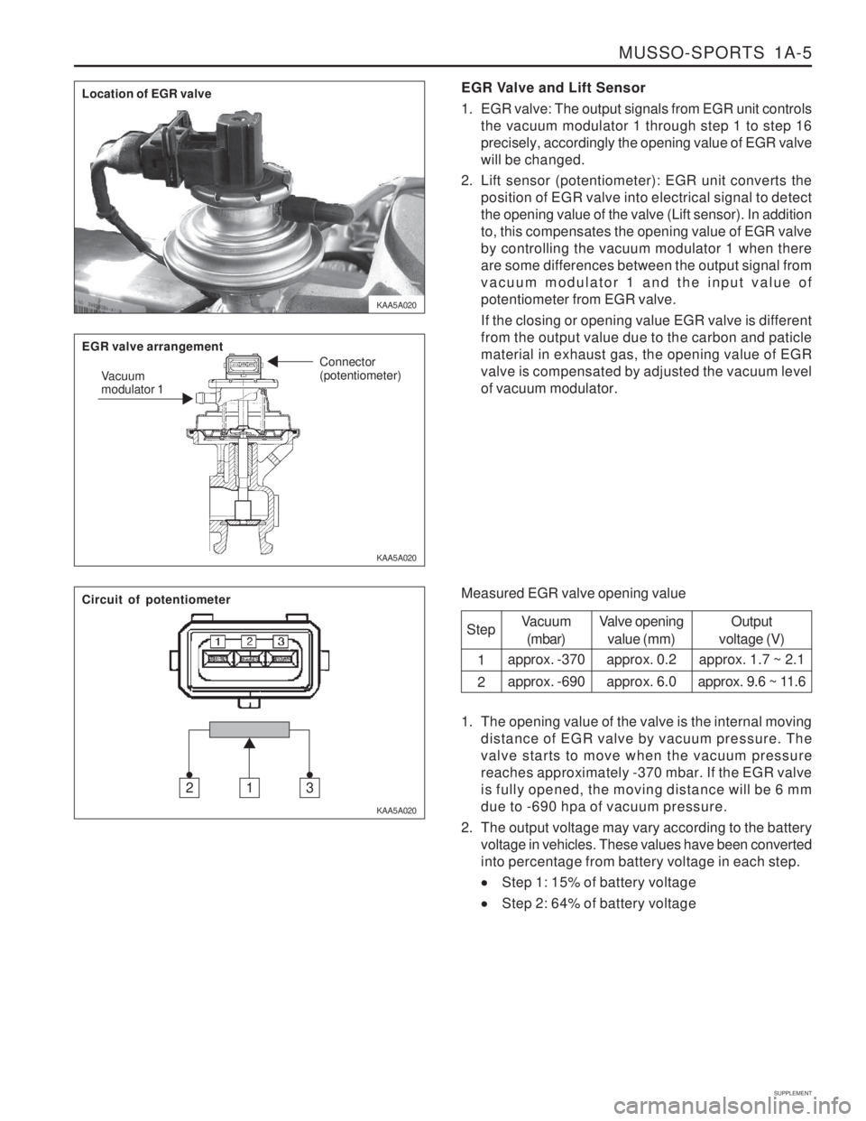
KAA5A020EGR Valve and Lift Sensor
1. EGR valve: The output signals from EGR unit controls
the vacuum modulator 1 through step 1 to step 16 precisely, accordingly the opening value of EGR valvewill be changed.
2. Lift sensor (potentiometer): EGR unit converts the position of EGR valve into electrical signal to detectthe opening value of the valve (Lift sensor). In additionto, this compensates the opening value of EGR valveby controlling the vacuum modulator 1 when thereare some differences between the output signal fromvacuum modulator 1 and the input value ofpotentiometer from EGR valve. If the closing or opening value EGR valve is different from the output value due to the carbon and paticlematerial in exhaust gas, the opening value of EGRvalve is compensated by adjusted the vacuum levelof vacuum modulator.
Measured EGR valve opening value Step 1 2
Vacuum(mbar)
approx. -370 approx. -690 Valve opening
value (mm)
approx. 0.2approx. 6.0 Output
voltage (V)
approx. 1.7 ~ 2.1
approx. 9.6 ~ 11.6
1. The opening value of the valve is the internal moving distance of EGR valve by vacuum pressure. The valve starts to move when the vacuum pressurereaches approximately -370 mbar. If the EGR valveis fully opened, the moving distance will be 6 mmdue to -690 hpa of vacuum pressure.
2. The output voltage may vary according to the battery voltage in vehicles. These values have been convertedinto percentage from battery voltage in each step.
Step 1: 15% of battery voltage
Step 2: 64% of battery voltage
Location of EGR valve EGR valve arrangement
Vacuum modulator 1 Connector (potentiometer)
Circuit of potentiometer
312
Page 1340 of 1574
1A-28 MUSSO-SPORTS
SUPPLEMENT
30 BAT+
15 IGN 1
58 ILL
31 GND
2 3
107
B E
ClusterL
20 388
6 B4
B2 Multi-Function Switch
(Turn Signal Switch)
GY GY B1
RH
LH
5 9
ILL OFF ON
4
Hazard
Switch
G204 G301
G201
E
f10
10A
F2110A E
f9
60A
F7 15A
1 GW
YB BG RG
GW LY
GL YW
B
BB
B Blinker Unit Y
W
GR
GR
4
S202 E
f2 80A
2 4G
G W
G
G
1 2
G
G102 G204
3 1
G303
24
G101
G101 31
FRT LH
Turn Signal Lamp
(Head Lamp)
RR LH
Turn SignalLamp
(Tail Lamp) FRT RH
Turn Signal Lamp
(Head Lamp)
RR RH
Turn SignalLamp
(Tail Lamp)
"28"
Cluster
YYY
B
B
B "25"
Cluster
C905 2
C203
5
C904 2 C108
C206
C905 8
3 C904
3
C101
4
C1031
11C905
6
C101
17
Fender Fender
C904
7
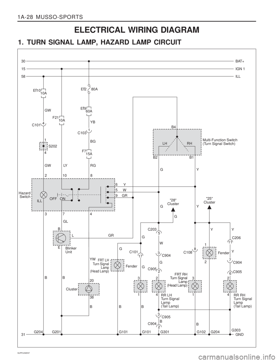
ELECTRICAL WIRING DIAGRAM
1. TURN SIGNAL LAMP, HAZARD LAMP CIRCUIT
Page 1348 of 1574
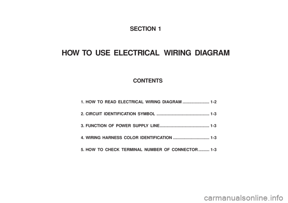
1. HOW TO READ ELECTRICAL WIRING DIAGRAM ........................ 1-2
2. CIRCUIT IDENTIFICATION SYMBOL ............................................... 1-3
3. FUNCTION OF POWER SUPPLY LINE ............................................ 1-3
4. WIRING HARNESS COLOR IDENTIFICATION................................ 1-3
5. HOW TO CHECK TERMINAL NUMBER OF CONNECTOR .......... 1-3 CONTENTS
SECTION 1
HOW TO USE ELECTRICAL WIRING DIAGRAM
Page 1349 of 1574
1-2 HOW TO USE ELECTRICAL WIRING DIAGRAM
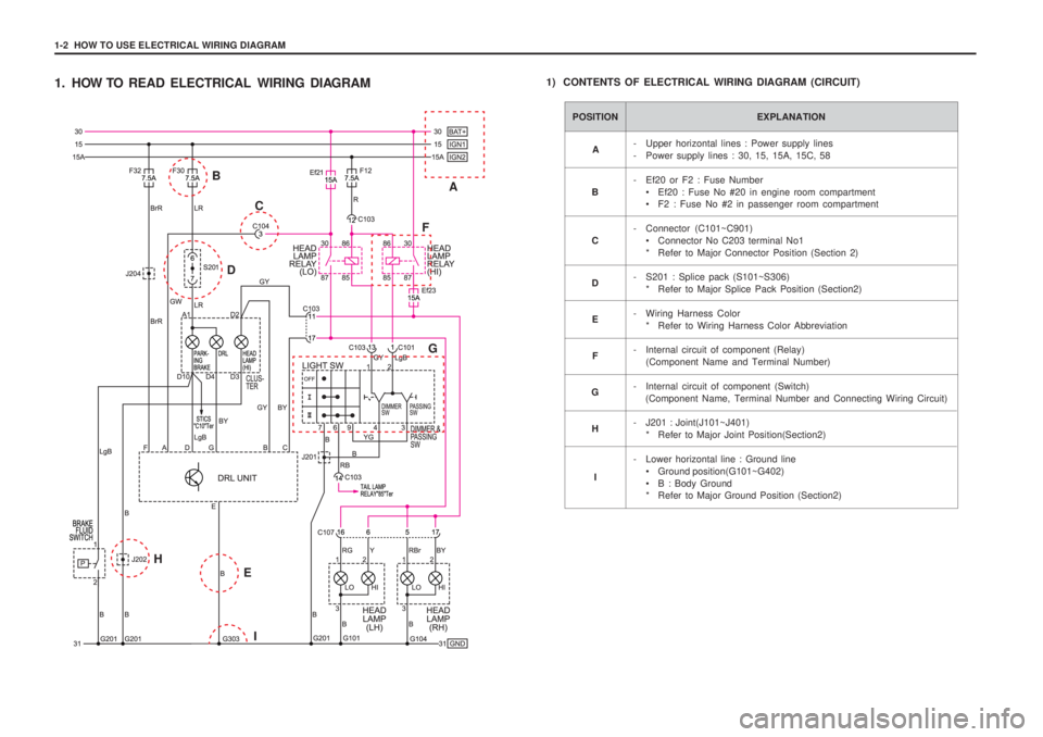
1. HOW TO READ ELECTRICAL WIRING DIAGRAM1) CONTENTS OF ELECTRICAL WIRING DIAGRAM (CIRCUIT)
POSITION EXPLANATION
- Upper horizontal lines : Power supply lines
- Power supply lines : 30, 15, 15A, 15C, 58
- Ef20 or F2 : Fuse Number
• Ef20 : Fuse No #20 in engine room compartment
F2 : Fuse No #2 in passenger room compartment
- Connector (C101~C901) Connector No C203 terminal No1
* Refer to Major Connector Position (Section 2)
- S201 : Splice pack (S101~S306) * Refer to Major Splice Pack Position (Section2)
- Wiring Harness Color * Refer to Wiring Harness Color Abbreviation
- Internal circuit of component (Relay) (Component Name and Terminal Number)
- Internal circuit of component (Switch) (Component Name, Terminal Number and Connecting Wiring Circuit)
- J201 : Joint(J101~J401) * Refer to Major Joint Position(Section2)
- Lower horizontal line : Ground line Ground position(G101~G402)
B : Body Ground
* Refer to Major Ground Position (Section2)
A
B C D E
F
G
H
I
A
B
C
D F
G
E I
H
Page 1350 of 1574
HOW TO USE ELECTRICAL WIRING DIAGRAM 1-3
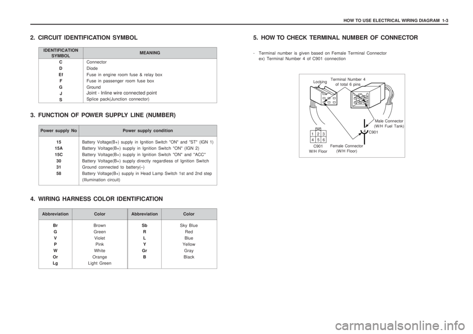
Connector DiodeFuse in engine room fuse & relay box Fuse in passenger room fuse box Ground Joint - Inline wire connected point Splice pack(Junction connector)
C D
Ef F
G J
S
2. CIRCUIT IDENTIFICATION SYMBOL
3. FUNCTION OF POWER SUPPLY LINE (NUMBER)
IDENTIFICATION SYMBOL MEANING
Power supply No Power supply condition
Battery Voltage(B+) supply in Ignition Switch "ON" and "ST" (IGN 1)
Battery Voltage(B+) supply in Ignition Switch "ON" (IGN 2) Battery Voltage(B+) supply in Ignition Switch "ON" and "ACC"Battery Voltage(B+) supply directly regardless of Ignition Switch Ground connected to battery(
–)
Battery Voltage(B+) supply in Head Lamp Switch 1st and 2nd step
(Illumination circuit)
15
15A 15C
30 31 58
Abbreviation Color
BrownGreen Violet Pink
White
Orange
Light Green
Br
GV P
W
Or
LgAbbreviation Color
Sky BlueRed
Blue
Yellow
Gray
Black
Sb
RL Y
Gr B
4. WIRING HARNESS COLOR IDENTIFICATION 5. HOW TO CHECK
TERMINAL NUMBER OF CONNECTOR
- Terminal number is given based on Female Terminal Connector ex) Terminal Number 4 of C901 connection
Locking Terminal Number 4
of total 6 pins
Male Connector
(W/H Fuel Tank)
4 C901
Female Connector (W/H Floor)
C901
W/H Floor 13
2
46 5
Page 1369 of 1574
CONTENTS
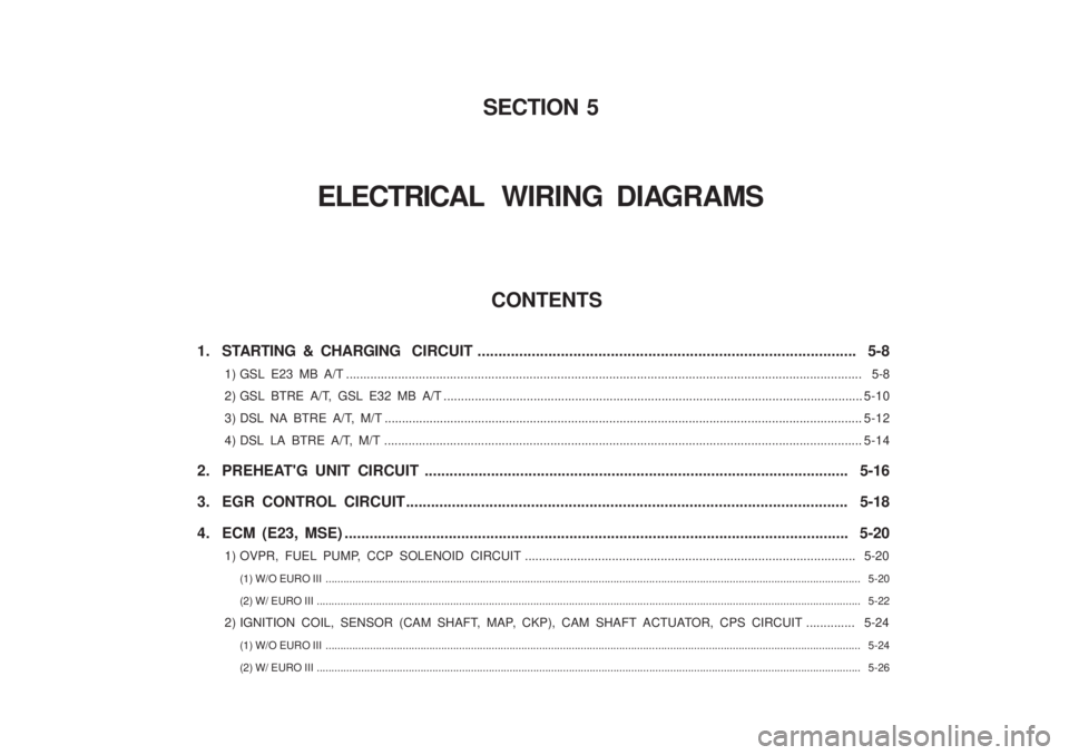
1. STARTING & CHARGING CIRCUIT ........................................................................................... 5-8
1) GSL E23 MB A/T ............................................................................................................... ...................................... 5-8
2) GSL BTRE A/T, GSL E32 MB A/T ................................................................................................. ........................5-10
3) DSL NA BTRE A/T, M/T ......................................................................................................... .................................5-12
4) DSL LA BTRE A/T, M/T ......................................................................................................... .................................5-14
2. PREHEAT'G UNIT CIRCUIT ...................................................................................................... 5-16
3. EGR CONTROL CIRCUIT.......................................................................................................... 5-18
4. ECM (E23, MSE) ............................................................................................................... .......... 5-20
1) OVPR, FUEL PUMP, CCP SOLENOID CIRCUIT ........................................................................................ ....... 5-20
(1) W/O EURO III ............................................................................................................... ..................................................................... 5-20
(2) W/ EURO III ................................................................................................................ ....................................................................... 5-22
2) IGNITION COIL, SENSOR (CAM SHAFT, MAP, CKP), CAM SHAFT ACTUATOR, CPS CIRCUIT .............. 5-24 (1) W/O EURO III ............................................................................................................... ..................................................................... 5-24
(2) W/ EURO III ................................................................................................................ ....................................................................... 5-26
SECTION 5
ELECTRICAL WIRING DIAGRAMS
Page 1373 of 1574
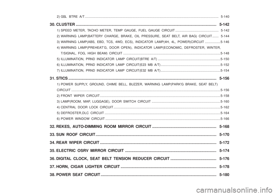
2 ) GSL BTRE A/T ..................................................................................................................................................... 5-140
30. CLUSTER ............................................................................................................................... ... 5-142
1) SPEED METER, TACHO METER, TEMP GAUGE, FUEL GAUGE CIRCUIT ................................................ 5-142
2) WARNING LAMP(BA TTERY CHARGE, BRAKE, OIL PRESSURE, SEAT BELT, AIR BAG) CIRCUIT ....... 5-144
3) WARNING LAMP(ABS, EBD, TCS, 4WD, ECS), INDICATOR LAMP(4H, 4L, POWER)CIRCUIT ................. 5-146
4) WARNING LAMP(PREHEA T’G, DOOR OPEN), INDICATOR LAMP(ECONOMIC, DEFROSTER, WINTER,
T/SIGNAL, FOG, HIGH BEAM) CIRCUIT .............................................................................................. ..............5-148
5) ILLUMINATION, PRND INDICATOR LAMP CIRCUIT(BTRE A/T) ..................................................................... 5-150
6) ILLUMINATION, PRND INDICATOR LAMP CIRCUIT(E23 MB A/T) .................................................................. 5-152
7) ILLUMINATION, PRND INDICATOR LAMP CIRCUIT(E32 MB A/T) .................................................................. 5-154
31. STICS ....................................................................................................................... .................. 5-156
1) POWER SUPPLY, GROUND, CHIME BELL, BUZZER, WARNING LAMP(PARK'G BRAKE, SEAT BELT)
CIRCUIT ...................................................................................................................................................................... 5-156
2) FRONT WIPER CIRCUIT ...................................................................................................................................... 5-158
3) LAMP(ROOM, MAP, LUGGAGE), DOOR SWITCH CIRCUIT ............................................................................ 5-160
4) CENTRAL DOOR LOCK CIRCUIT ....................................................................................................................... 5-162
5) DEFROSTER,DLC CIRCUIT ............................................................................................................................... ..5-164
6) POWER WINDOW CIRCUIT ............................................................................................................................... .5-166
32. REKES, AUTO-DIMMING ROOM MIRROR CIRCUIT ............................................................ 5-168
33. SUN ROOF CIRCUIT ............................................................................................................ .... 5-170
34. REAR WIPER CIRCUIT .......................................................................................................... .. 5-172
35. ELECTRIC OSRV MIRROR CIRCUIT ..................................................................................... 5-174
36. DIGITAL CLOCK, SEAT BELT TENSION REDUCER CIRCUIT ........................................... 5-176
37. HORN, CIGAR LIGHTER CIRCUIT ......................................................................................... 5-178
38. POWER SEAT CIRCUIT ........................................................................................................... 5-180