2003 SKODA FABIA clock
[x] Cancel search: clockPage 4 of 233

Contents3
Contents
Layout of this Owner's
Manual
. . . . . . . . . . . . . . . . . . . . . . . . . . . . .
Using the system . . . . . . . . . . . . . . .
Cockpit . . . . . . . . . . . . . . . . . . . . . . . . . . . . . . .
An overview . . . . . . . . . . . . . . . . . . . . . . . . . .
Instruments and Indicator/Warning LightsGeneral view of the instrument cluster . . . . . .
Engine revolutions counter . . . . . . . . . . . . . . .
Coolant temperature gauge . . . . . . . . . . . . . .
Fuel gauge . . . . . . . . . . . . . . . . . . . . . . . . . . .
Speedometer with counter for distance driven
Service Interval Display . . . . . . . . . . . . . . . . .
Digital clock . . . . . . . . . . . . . . . . . . . . . . . . . .
Multi-functional indicator* . . . . . . . . . . . . . . . .
Information display* . . . . . . . . . . . . . . . . . . . .
Auto Check Control . . . . . . . . . . . . . . . . . . . .
Warning lights . . . . . . . . . . . . . . . . . . . . . . . . .
Unlocking and locking . . . . . . . . . . . . . . . . . .
Keys . . . . . . . . . . . . . . . . . . . . . . . . . . . . . . . .
Changing the key battery . . . . . . . . . . . . . . . .
Electronic immobiliser . . . . . . . . . . . . . . . . . .
Locking . . . . . . . . . . . . . . . . . . . . . . . . . . . . . .
Child safety locks . . . . . . . . . . . . . . . . . . . . . .
Central locking system* . . . . . . . . . . . . . . . . .
Remote control* . . . . . . . . . . . . . . . . . . . . . . .
Synchronisation of the vehicle key code . . . .
Anti-theft alarm system* . . . . . . . . . . . . . . . . .
Power windows* . . . . . . . . . . . . . . . . . . . . . . .
Electric sliding/tilting roof* . . . . . . . . . . . . . . .
Lights and Visibility . . . . . . . . . . . . . . . . . . . .
Lights . . . . . . . . . . . . . . . . . . . . . . . . . . . . . . .
Interior lighting . . . . . . . . . . . . . . . . . . . . . . . .
Visibility . . . . . . . . . . . . . . . . . . . . . . . . . . . . .
The windscreen wiper and washing system .
Rear-view mirror . . . . . . . . . . . . . . . . . . . . . .
Seats and Stowage . . . . . . . . . . . . . . . . . . . .
Front seats . . . . . . . . . . . . . . . . . . . . . . . . . . .
Head restraints . . . . . . . . . . . . . . . . . . . . . . . .
Middle rear head restraints* . . . . . . . . . . . . . .
Heating the front seats* . . . . . . . . . . . . . . . . .
Rear seats . . . . . . . . . . . . . . . . . . . . . . . . . . .
Pedals . . . . . . . . . . . . . . . . . . . . . . . . . . . . . .
Luggage compartment . . . . . . . . . . . . . . . . . .
Net partition (Estate)* . . . . . . . . . . . . . . . . . . .
The roof luggage rack system* . . . . . . . . . . .
Drinks can holder* . . . . . . . . . . . . . . . . . . . . .
Note holder . . . . . . . . . . . . . . . . . . . . . . . . . .
Ashtray at the front* . . . . . . . . . . . . . . . . . . . .
Ashtray at the rear* . . . . . . . . . . . . . . . . . . . .
Cigarette lighter* and power socket* . . . . . . .
Storage compartments . . . . . . . . . . . . . . . . . .
Heating and air conditioning system . . . . .
Heating . . . . . . . . . . . . . . . . . . . . . . . . . . . . . .
The air conditioning system* . . . . . . . . . . . . .
Starting-off and Driving. . . . . . . . . . . . . . . . .
Setting steering wheel position* . . . . . . . . . . .
Ignition lock . . . . . . . . . . . . . . . . . . . . . . . . . .
Starting engine . . . . . . . . . . . . . . . . . . . . . . . .
Shifting gear (on a manual gearbox) . . . . . . .
Handbrake . . . . . . . . . . . . . . . . . . . . . . . . . . .
Parking aid* . . . . . . . . . . . . . . . . . . . . . . . . . .
Cruise control system (CCS)* . . . . . . . . . . . .
Automatic gearbox*. . . . . . . . . . . . . . . . . . . .
4-speed automatic gearbox . . . . . . . . . . . . . .
Communication . . . . . . . . . . . . . . . . . . . . . . .
Universal telephone connection* . . . . . . . . . .
Mobile phones and two-way radio systems . .
The CD changer* . . . . . . . . . . . . . . . . . . . . . .
Safety. . . . . . . . . . . . . . . . . . . . . . . . . . . . . .
Passive Safety . . . . . . . . . . . . . . . . . . . . . . . .
Driving the safe way . . . . . . . . . . . . . . . . . . .
Requirements for maximum safety . . . . . . . .
Seat belts. . . . . . . . . . . . . . . . . . . . . . . . . . . . .
Why seat belts? . . . . . . . . . . . . . . . . . . . . . . .
The physical principle of a frontal collision . .
Important safety information regarding the use
of seat belts . . . . . . . . . . . . . . . . . . . . . . . . . .
How are seat belts correctly fastened? . . . . .
Belt tensioners . . . . . . . . . . . . . . . . . . . . . . . .
Airbag system. . . . . . . . . . . . . . . . . . . . . . . . .
Description of the airbag system . . . . . . . . . .
Front airbags . . . . . . . . . . . . . . . . . . . . . . . . .
Side airbags* . . . . . . . . . . . . . . . . . . . . . . . . .
Deactivating an airbag . . . . . . . . . . . . . . . . . .
Transporting children safely . . . . . . . . . . . .
What you should know about transporting
children! . . . . . . . . . . . . . . . . . . . . . . . . . . . . .
Child seat . . . . . . . . . . . . . . . . . . . . . . . . . . . .
Attaching a child seat using the “ISOFIX”
system* . . . . . . . . . . . . . . . . . . . . . . . . . . . . .
7
9
11
11
12
12
13
13
14
14
15
16
17
21
23
27
37
37
38
39
39
39
40
44
45
46
47
49 52
52
56
58
59
62
63
63
65
66
66
67
69
69
73
76
78
78
79
79
80
81
87
87
90
95
95
95
96
98
99
100
100 103
103
108
108
109
109
111
111
111
111
11 2
11 2
11 3
11 4
11 5
11 8
120
120
122
124
127
130
130
134
138
Page 13 of 233

Instruments and Indicator/Warning Lights
12
Instruments and Indicator/Warning Lights
General view of the instrument cluster
Fig. 3 Instrument cluster
Engine revolutions counter ⇒page 13
Coolant temperature gauge ⇒page 13
Fuel gauge ⇒page 14
Speedometer
− with counter for distance driven ⇒page 14
− with trip counter for distance driven ⇒page 14 −
with Service Interval Display ⇒page 15
Digital clock ⇒page 16 and multi-functional indicator* ⇒page 17
Information display* ⇒page 21
When the lights are switched on, the instrument cluster is illuminated.A1
A2
A3
A4
A5
A6
Page 17 of 233

Instruments and Indicator/Warning Lights
16
Resetting Service Interval Display
We recommend having this resetting performed by a Škoda Dealer.
Škoda dealer:
•resets the memory of the display after the appropriate inspection;
•makes an entry in the Service Schedule;
•affix the sticker to the side of the dash panel on the driver's side, where
the following service interval is shown.
The service interval displays can also be reset as follows by using the
reset button for the counter for distance driven:
Models with fixed service intervals (QG0)
Switch off the ignition, press the reset button of the trip counter for
distance driven and hold it down.
Switching the ignition on causes a service interval to appear in the display.
Holding the reset button down for 10 seconds will cause the counter to be
reset (the display shows “- - -” and then the trip counter readout).
The readout OIL will appear in the display after resetting the indicator
INSP and releasing the reset button when both service intervals (INSP
and OIL) were reached together.
Repress the reset button and hold it down for 10 seconds to also reset this
interval.
Vehicles with extended service intervals (QG1 and QG2)
Switch off the ignition, press the reset button of the trip counter for
distance driven and hold it down.
Switch the ignition on and release the reset button. Now turn the reset
button to the right. All counters will be reset to 0.
Caution
We recommend that you do not reset the Service Interval Display yourself
otherwise this can result in the service interval display being incorrectly
set, which may also result in problems with operation of your vehicle.
Note
•Information is retained in the Service Interval Display also after the
battery of the vehicle is disconnected.
•It is necessary to re-code the Service Interval Display if a new instru-
ment cluster is installed during repair work. this work is carried out by a
Škoda dealer.
•Never reset the display between service intervals otherwise this may
result in incorrect readouts.
•The data displayed is the same after resetting the display with flexible
service intervals (QG1) using the reset button as that for a vehicle with
fixed service intervals (QG2).
•We therefore recommend having the Service Interval Display reset
only by a Škoda dealer who is familiar with the procedure for resetting the
display with a vehicle system tester.
•Please refer to the brochure Service Plan for extensive information
about the service intervals.
Digital clock
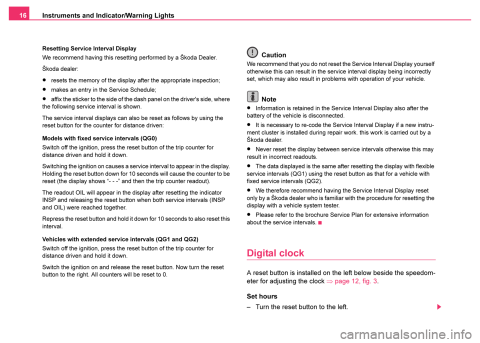
A reset button is installed on the left below beside the speedom-
eter for adjusting the clock ⇒page 12, fig. 3 .
Set hours
– Turn the reset button to the left.
Page 18 of 233

Instruments and Indicator/Warning Lights17
Using the systemSafetyDriving TipsGeneral MaintenanceBreakdown assist-
anceTechnical DataFabia Praktik
Setting minutes
– Turn the reset button to the right.
Multi-functional indicator*
Introduction
The multi-functional indicator appears in the display of the revolutions
counter ⇒fig. 6 or in the information display ⇒page 21, fig. 9 depending
on the equipment fitted to your vehicle.
The multi-functional indicator offers you a range of useful information.
Note
In certain national versions the displays appear in the Imperial system of
measures.
Memory
The multi-functional indicator is equipped with two automatic memories.
You can see the memory which is currently being shown in the display
from the negatively displayed number ⇒fig. 6 . The data of the single-trip
memory (memory 1) is shown if a 1 appears in the display. A 2 shown in
the display means that data relates to the total distance memory (memory
2).
Switching of the memory takes place when the button ⇒page 18,
fig. 7 .
WARNING
The clock should not be adjusted while driving for safety reasons
but only when the vehicle is stationary.
The outside temperature⇒page 19
Range⇒page 19
Current fuel consumption⇒page 20
Average fuel consumption⇒page 20
Driving time⇒page 20
Distance driven⇒page 20
Average speed⇒page 20
Fig. 6 Display in
engine revolutions
counter Multi-func-
tional indicator
AB
Page 170 of 233

Fuel169
Using the systemSafetyDriving TipsGeneral MaintenanceBreakdown assist-
anceTechnical DataFabia Praktik
Prewarming fuel
The vehicle is fitted with a fuel filter prewarming system. This secures
operation of a vehicle using diesel fuel down to an environmental temper-
ature of -25°C.
Biofuel
We recommend refuelling with diesel fuel at temperatures below -10°C.
Caution
It is not permitted to add the various fuel additives on the market, including
petrol, to diesel fuel in order to improve its flow properties.
RefuellingOpening the fuel filler cap
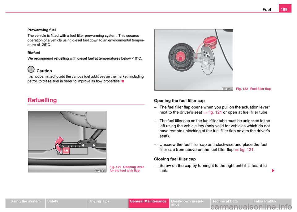
– The fuel filler flap opens when you pull on the actuation lever*
next to the driver's seat ⇒fig. 121 or open at fuel filler tube.
– The fuel filler cap on the fuel filler tube must be unlocked to the left using the vehicle key (only valid for vehicles which do not
have remote unlocking of the fuel filler flap next to the driver's
seat).
– Unscrew the fuel filler cap anti-clockwise and place the fuel filler cap from above on the fuel filler flap ⇒fig. 121 .
Closing fuel filler cap
– Screw on the cap by turning it to the right until it is heard to lock.
Fig. 121 Opening lever
for the fuel tank flap
Fig. 122 Fuel filler flap
Page 207 of 233

Breakdown assistance
206
Front towing eye
The towing eye is stored in the box for the vehicle tool kit.
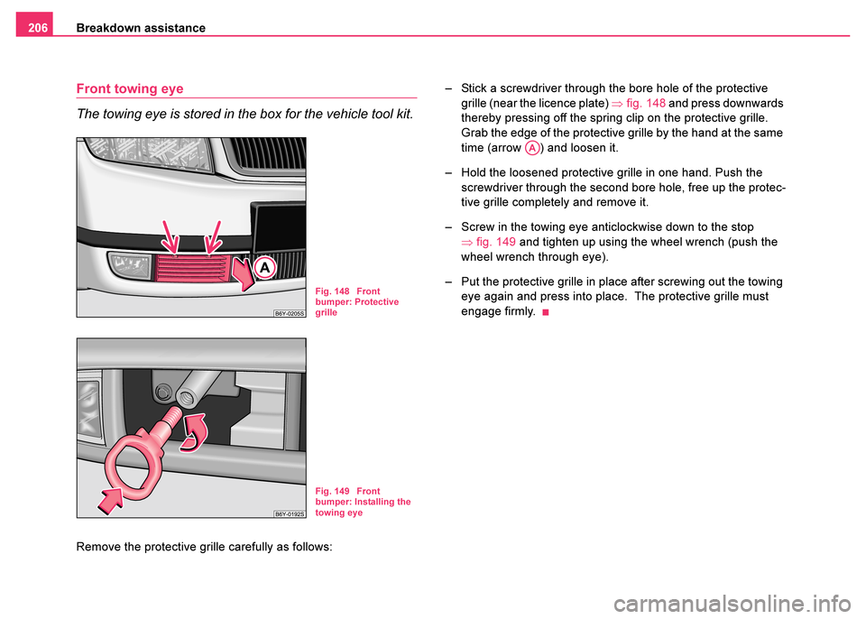
Remove the protective grille carefully as follows: – Stick a screwdriver through the bore hole of the protective
grille (near the licence plate) ⇒fig. 148 and press downwards
thereby pressing off the spring clip on the protective grille.
Grab the edge of the protective grille by the hand at the same
time (arrow ) and loosen it.
– Hold the loosened protective grille in one hand. Push the screwdriver through the second bore hole, free up the protec-
tive grille completely and remove it.
– Screw in the towing eye anticlockwise down to the stop ⇒fig. 149 and tighten up using the wheel wrench (push the
wheel wrench through eye).
– Put the protective grille in place after screwing out the towing eye again and press into place. The protective grille must
engage firmly.
Fig. 148 Front
bumper: Protective
grille
Fig. 149 Front
bumper: Installing the
towing eye
AA
Page 217 of 233

Fuses and light bulbs
216
– Insert the lamp holder with new light bulb into of the headlight.
Low beam
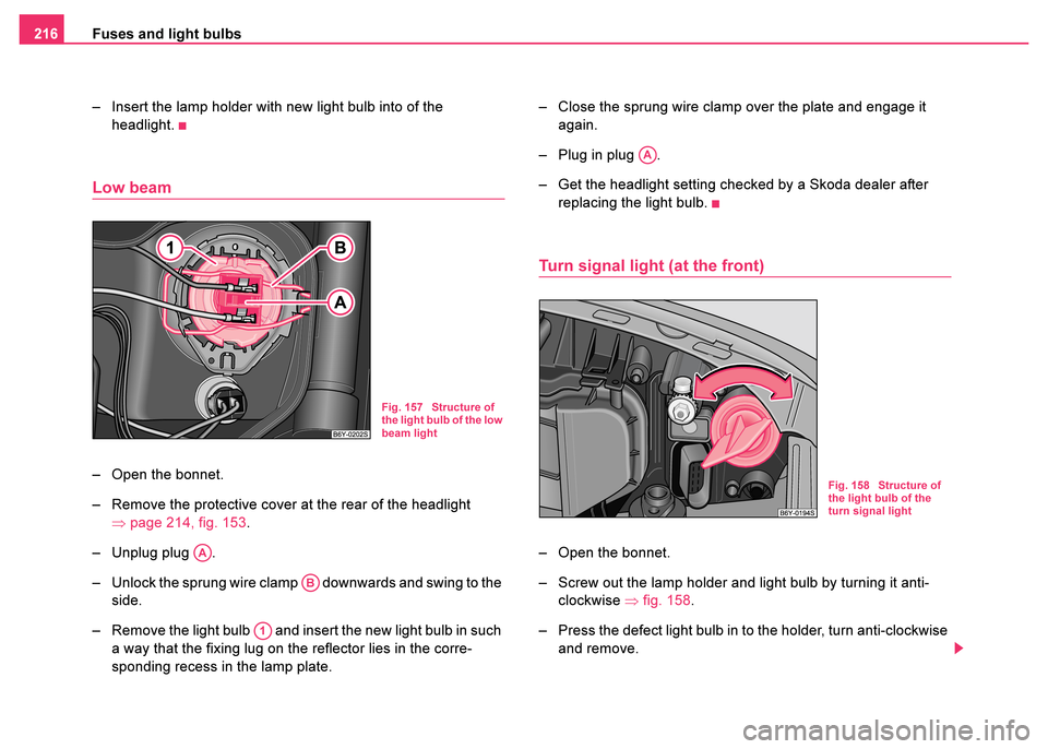
– Open the bonnet.
– Remove the protective cover at the rear of the headlight ⇒page 214, fig. 153 .
– Unplug plug .
– Unlock the sprung wire clamp downwards and swing to the side.
– Remove the light bulb and insert the new light bulb in such a way that the fixing lug on the reflector lies in the corre-
sponding recess in the lamp plate. – Close the sprung wire clamp over the plate and engage it
again.
– Plug in plug .
– Get the headlight setting checked by a Skoda dealer after replacing the light bulb.
Turn signal light (at the front)
– Open the bonnet.
– Screw out the lamp holder and light bulb by turning it anti-clockwise ⇒fig. 158 .
– Press the defect light bulb in to the holder, turn anti-clockwise and remove.
Fig. 157 Structure of
the light bulb of the low
beam light
AA
AB
A1
AA
Fig. 158 Structure of
the light bulb of the
turn signal light
Page 221 of 233

Fuses and light bulbs
220
Rear light unit
– Open the boot lid/luggage compartment door.
– Push the cover to the side carefully.
– Press the fixing straps in the upper part of the light bulb holder
in the direction of the arrow and remove the light bulb holder
⇒fig. 165 .
– Press the defect light bulb in to the holder, turn anti-clockwise and remove.
– Insert the new light bulb and turn it fully to the right.
– Insert the light bulb holder into the opening of the rear light from below and interlock the fixing straps into the upper part.
– Push the cover back into place.
Rear light unit (estate car, sedan)
– Open the boot lid/luggage compartment door.
– Remove the cover in the boot.
– Press the catch in direction of arrow and pull out the light bulb holder.
– Press the defect light bulb in to the holder, turn anti-clockwise and remove.
– Insert the new light bulb and turn it fully to the right.
– Insert the light bulb holder again, the plastic tongue must lock in place.
– Install the cover in the boot.
Fig. 165 Remove light
bulb holderFig. 166 Remove the
light bulb holder
(estate car, sedan)