2003 NISSAN XTERRA glove box
[x] Cancel search: glove boxPage 20 of 272

1. Crash zone sensor
2.
Passenger supplemental air bag module
3. Passenger seat belt buckle switch
4. Side curtain air bag
5. Front seat belt pre-tensioner6. Driver seat belt buckle switch
7. Air bag diagnosis sensor unit
8. Front seat belt pre-tensioner
9. Driver supplemental air bag module
Supplemental front air bag system
The driver supplemental front air bag is located in
the center of the steering wheel. The passenger
supplemental front air bag is mounted in the
dashboard above the glove box.
These systems are designed to meet optional
certification requirements under U.S. regulations.
They are also permitted in Canada. The optional
certification allows the front air bags to be de-
signed to inflate somewhat less forcefully than
previously.However, all of the information,
cautions and warnings in this manual still
apply and must be followed.
The supplemental front air bag system is de-
signed to inflate in higher severity frontal colli-
sions, although it may inflate if the forces in an-
other type of collision are similar to those of a
higher severity frontal impact. It may not inflate in
certain frontal collisions. Vehicle damage (or lack
of it) is not always an indication of proper supple-
mental front air bag system operation.
The supplemental air bag system has dual stage
inflators for both the driver and passenger air
bags. The system monitors information from the
crash zone sensor, the diagnosis sensor unit and
seat belt buckle sensors that detect if the seat
belts are fastened. Inflator operation is based on
the severity of a collision and whether the seat
belts are being used. Only one front air bag may
WRS0237
1-14Seats, restraints and supplemental air bag systems
ZREVIEW COPY:Ð2003 Xterra(xtr)
Owners Manual(owners)ÐUSA English(nna)
02/21/03Ðtbrooks
X
Page 53 of 272

2 Instruments and controls
Instrument panel...................................2-2
Meters and gauges................................2-3
Speedometer and odometer.....................2-3
Tachometer....................................2-5
Engine coolant temperature gauge...............2-5
Fuel gauge....................................2-6
Compass and outside temperature display
(if so equipped)...................................2-6
Outside temperature display.....................2-7
Compass display...............................2-7
Warning/indicator lights and audible reminders.......2-9
Checking bulbs................................2-9
Warning lights................................2-10
Indicator lights................................2-13
Audible reminders.............................2-15
Security systems.................................2-15
Vehicle security system (if so equipped)..........2-15
Windshield wiper and washer switch...............2-18
Switch operation..............................2-18
Rear window wiper and washer switch..............2-19
Rear window defroster switch......................2-20
Headlight and turn signal switch....................2-20
Headlight control switch........................2-20
Fog light switch (if so equipped)...................2-22Hazard warning flasher switch.....................2-22
Horn............................................2-23
Vehicle dynamic control (VDC) off switch
(if so equipped)..................................2-23
Power outlet (if so equipped)......................2-24
Storage.........................................2-25
Storage compartment..........................2-25
Roof headliner net (if so equipped)..............2-26
Map pocket...................................2-26
Cup holders..................................2-27
Glove box....................................2-27
Console box (if so equipped)...................2-28
Luggage hooks (if so equipped).................2-29
Tonneau cover (if so equipped)..................2-30
Windows........................................2-31
Power windows (if so equipped)................2-31
Manual windows..............................2-33
Sunroof (if so equipped)...........................2-33
Manual sunroof................................2-33
Removing/installing............................2-34
Interior light......................................2-35
Map lights (if so equipped)........................2-35
Illuminated entry system...........................2-36
Battery saver (if so equipped)...................2-36
ZREVIEW COPY:Ð2003 Xterra(xtr)
Owners Manual(owners)ÐUSA English(nna)
02/21/03Ðtbrooks
X
Page 54 of 272

1. Headlight/turn signal switch
2. Meters and gauges
3. Windshield wiper/washer switch
4. Power point
5. Heater and air conditioner
6. Front passenger supplemental air bag
7. Glove box
8. Audio system
9. Hazard warning flasher switch
10. Automatic/manual selector lever
11. Transfer case shift lever (if so
equipped)
12. Parking brake release lever
13. Cruise control main/set switch (if so
equipped)
14. Driver supplemental air bag
15. Steering wheel switch for audio con-
trols (if so equipped)
16. Vehicle dynamics control (VDC) off
switch (if so equipped)
WIC0366
INSTRUMENT PANEL
2-2Instruments and controls
ZREVIEW COPY:Ð2003 Xterra(xtr)
Owners Manual(owners)ÐUSA English(nna)
02/21/03Ðtbrooks
X
Page 79 of 272

CUP HOLDERS
WARNING
The cup holder should not be used while
driving so full attention may be given to
vehicle operation.
CAUTION
cAvoid abrupt starting and braking when
the cup holder is being used to prevent
spilling the drink. If the liquid is hot, it
can scald you or your passenger.cUse only soft cups in the cup holder.
Hard objects can injure you in an
accident.
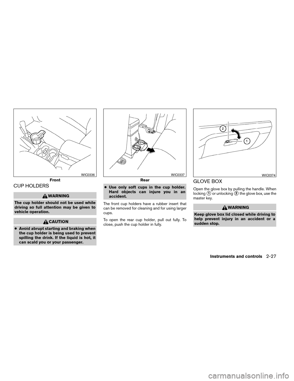
The front cup holders have a rubber insert that
can be removed for cleaning and for using larger
cups.
To open the rear cup holder, pull out fully. To
close, push the cup holder in fully.
GLOVE BOX
Open the glove box by pulling the handle. When
locking
s1or unlockings2the glove box, use the
master key.
WARNING
Keep glove box lid closed while driving to
help prevent injury in an accident or a
sudden stop.
Front
WIC0336
Rear
WIC0337WIC0374
Instruments and controls2-27
ZREVIEW COPY:Ð2003 Xterra(xtr)
Owners Manual(owners)ÐUSA English(nna)
02/21/03Ðtbrooks
X
Page 173 of 272

4. Lower the vehicle slowly until the tire
touches the ground. Then, with the wheel
nut wrench, tighten the wheel nuts securely
in the sequence illustrated. Lower the ve-
hicle completely.
WARNING
cIncorrect wheel nuts or improperly
tightened wheel nuts can cause the
wheel to become loose or come off.
This could cause an accident.
cDo not use oil or grease on the wheel
studs or nuts. This could cause the nuts
to become loose.
cRetighten the wheel nuts when the ve-
hicle has been driven for 600 miles
(1,000 km) (also in cases of a flat tire,
etc.) .
As soon as possible, tighten the wheel nuts
to the specified torque with a torque
wrench.
Wheel nut tightening torque:
98 ft-lb (133 N·m)
The wheel nuts must be kept tightened to
specification at all times. It is recom-
mended that wheel nuts be tightened to
specifications at each lubrication interval.Adjust tire pressure to the COLD pressure.
COLD pressure: After vehicle has been
parked for three hours or more or driven
less than 1 mile (1.6 km) .
COLD tire pressures are shown on the tire
placard affixed to the inside of the glove
box lid.
5. Securely store the flat tire and jacking equip-
ment in the vehicle.
WARNING
cAlways make sure that the spare tire
and jacking equipment are properly se-
cured after use. Such items can become
dangerous projectiles in an accident or
sudden stop.
cThe spare tire is designed for emer-
gency use. See specific instructions un-
der the heading “Wheels and tires” in
the “Maintenance and do-it-yourself”
section of this manual.To start your engine with a booster battery, the
instructions and precautions below must be fol-
lowed.
WARNING
cIf done incorrectly, jump starting can
lead to a battery explosion, resulting in
severe injury or death. It could also
damage your vehicle.
cExplosive hydrogen gas is always
present in the vicinity of the battery.
Keep all sparks and flames away from
the battery.
cDo not allow battery fluid to come into
contact with eyes, skin, clothing or
painted surfaces. Battery fluid is a cor-
rosive sulfuric acid solution which can
cause severe burns. If the fluid should
come into contact with anything, imme-
diately flush the contacted area with
water.
cKeep battery out of the reach of
children.
cThe booster battery must be rated at 12
volts. Use of an improperly rated battery
can damage your vehicle.
JUMP STARTING
In case of emergency6-9
ZREVIEW COPY:Ð2003 Xterra(xtr)
Owners Manual(owners)ÐUSA English(nna)
02/24/03Ðtbrooks
X
Page 209 of 272

WARNING
cOperating the engine with the air
cleaner removed can cause you or oth-
ers to be burned. The air cleaner not
only cleans the air, it stops the flame if
the engine backfires. If it isn’t there, and
the engine backfires, you could be
burned. Do not drive with the air cleaner
removed, and be careful when working
on the engine with the air cleaner
removed.cNever pour fuel into the throttle body or
attempt to start the engine with the air
cleaner removed. Doing so could result
in serious injury.
IN-CABIN MICROFILTER (if so
equipped)
The in-cabin microfilter restricts the entry of air-
borne dust and pollen particles and reduces
some objectionable outside odors. The filter is
located behind the glove box. Refer to the
“NISSAN Service and Maintenance Guide” for
change intervals.
To change the filter, perform the following proce-
dure:
1. Pivot pins
2. Glove box
1. Remove the two pivot pins from the glove
box. Remove the glove box.
CAUTION
Do not disturb the front of the air bag
module.
WDI0291WDI0315
Maintenance and do-it-yourself8-23
ZREVIEW COPY:Ð2003 Xterra(xtr)
Owners Manual(owners)ÐUSA English(nna)
02/24/03Ðtbrooks
X
Page 210 of 272

1. Reinforcement panel
2. Cooling unit
3. Screws
4. Clip
2. Remove the 7 screws and 1 clip from the
glove box frame. Remove the glove box
frame.
1. Colling unit
2. Clip
3. Remove the clip securing the filters in the
intake unit.
1. Cooling unit
2. Filter
4. Remove the filters.
NOTE:
The filters must be aligned with the plastic
hook at the bottom.
5. Insert the first filter in the bottom position.
Slide it up to the top position and insert the
second filter in the bottom position.
6. Secure the filter with the clip.
7. Install the glove box frame.
8. Install the glove box.
WDI0316WDI0317WDI0318
8-24Maintenance and do-it-yourself
ZREVIEW COPY:Ð2003 Xterra(xtr)
Owners Manual(owners)ÐUSA English(nna)
02/24/03Ðtbrooks
X
Page 211 of 272

1. Glove box
2. Label (small)
3. Label (large)
9. Fill out the date information on the small
label. Attach the small and large labels to the
glove box lid.
WDI0319
Maintenance and do-it-yourself8-25
ZREVIEW COPY:Ð2003 Xterra(xtr)
Owners Manual(owners)ÐUSA English(nna)
02/24/03Ðtbrooks
X