Page 2944 of 4179
PS-8
STEERING WHEEL
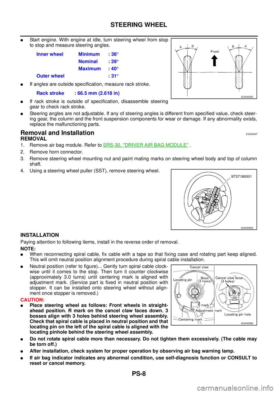
�Start engine. With engine at idle, turn steering wheel from stop
to stop and measure steering angles.
�If angles are outside specification, measure rack stroke.
�If rack stroke is outside of specification, disassemble steering
gear to check rack stroke.
�Steering angles are not adjustable. If any of steering angles is different from specified value, check steer-
ing gear, the column and the front suspension components for wear or damage. If any abnormality exists,
replace the malfunctioning parts.
Removal and InstallationEGS0004F
REMOVAL
1. Remove air bag module. Refer to SRS-30, "DRIVER AIR BAG MODULE" .
2. Remove horn connector.
3. Remove steering wheel mounting nut and paint mating marks on steering wheel body and top of column
shaft.
4. Using a steering wheel puller (SST), remove steering wheel.
INSTALLATION
Paying attention to following items, install in the reverse order of removal.
NOTE:
�When reconnecting spiral cable, fix cable with a tape so that fixing case and rotating part keep aligned.
This will omit neutral position alignment procedure during spiral cable installation.
�Neutral position (refer to figure)... Gently turn spiral cable clock-
wise until it comes to the stop. Then turn it counter clockwise
(approximately 3.0 turns) until centering mark is aligned with
adjustment mark. (Service part is fixed in neutral position with
stopper. It can be installed onto steering wheel without align-
ment once stopper is removed.)
CAUTION:
�Place steering wheel as follows: Front wheels in straight-
ahead position. R mark on the cancel claw faces down. 3
bosses align with 3 holes behind steering wheel assembly.
Check that spiral cable is placed in neutral position and that
locating pin on the left of the spiral cable is aligned with the
locating pinhole behind the steering wheel assembly.
�Do not rotate spiral cable more than necessary. Do not tighten them excessively. (The cable may
be torn off.)
�After installation, check system for proper operation by observing air bag warning lamp.
�If air bag indicator indicates any abnormal condition, use self-diagnosis function or CONSULT to
reset or cancel memory.Inner wheel Minimum : 36°
Nominal : 39°
Maximum : 40°
Outer wheel : 31°
Rack stroke : 66.5 mm (2.618 in)
SGIA0055E
SGIA0080E
SGIA0096E
Page 2960 of 4179
PS-24
POWER STEERING OIL PUMP
POWER STEERING OIL PUMPPFP:49110
On-Vehicle Inspection and ServiceEGS000AF
OIL PUMP PULLEY HYDRAULIC PRESSURE INSPECTION
Before starting following procedure, check tension of belt.
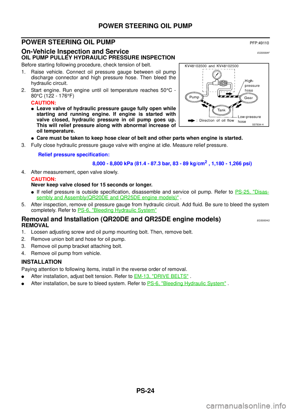
1. Raise vehicle. Connect oil pressure gauge between oil pump
discharge connector and high pressure hose. Then bleed the
hydraulic circuit.
2. Start engine. Run engine until oil temperature reaches 50°C -
80°C (122 - 176°F)
CAUTION:
�Leave valve of hydraulic pressure gauge fully open while
starting and running engine. If engine is started with
valve closed, hydraulic pressure in oil pump goes up.
This will relief pressure along with abnormal increase of
oil temperature.
�Care must be taken to keep hose clear of belt and other parts when engine is started.
3. Fully close hydraulic pressure gauge valve with engine at idle. Measure relief pressure.
4. After measurement, open valve slowly.
CAUTION:
Never keep valve closed for 15 seconds or longer.
�If relief pressure is outside specification, disassemble and service oil pump. Refer to PS-25, "Disas-
sembly and Assembly(QR20DE and QR25DE engine models)" .
5. After inspection, remove oil pressure gauge from hydraulic circuit. Add fluid. Be sure to bleed the system
completely. Refer to PS-6, "
Bleeding Hydraulic System"
Removal and Installation (QR20DE and QR25DE engine models)EGS000AG
REMOVAL
1. Loosen adjusting screw and oil pump mounting bolt. Then, remove belt.
2. Remove union bolt and hose for oil pump.
3. Remove oil pump bracket attaching bolt.
4. Remove oil pump from vehicle.
INSTALLATION
Paying attention to following items, install in the reverse order of removal.
�After installation, adjust belt tension. Refer to EM-13, "DRIVE BELTS" .
�After installation, be sure to bleed system. Refer to PS-6, "Bleeding Hydraulic System" . Relief pressure specification:
8,000 - 8,800 kPa (81.4 - 87.3 bar, 83 - 89 kg/cm
2 , 1,180 - 1,266 psi)
SST834-H
Page 2986 of 4179
SB-6
SEAT BELT WARNING SYSTEM
SEAT BELT WARNING SYSTEMPFP:25045
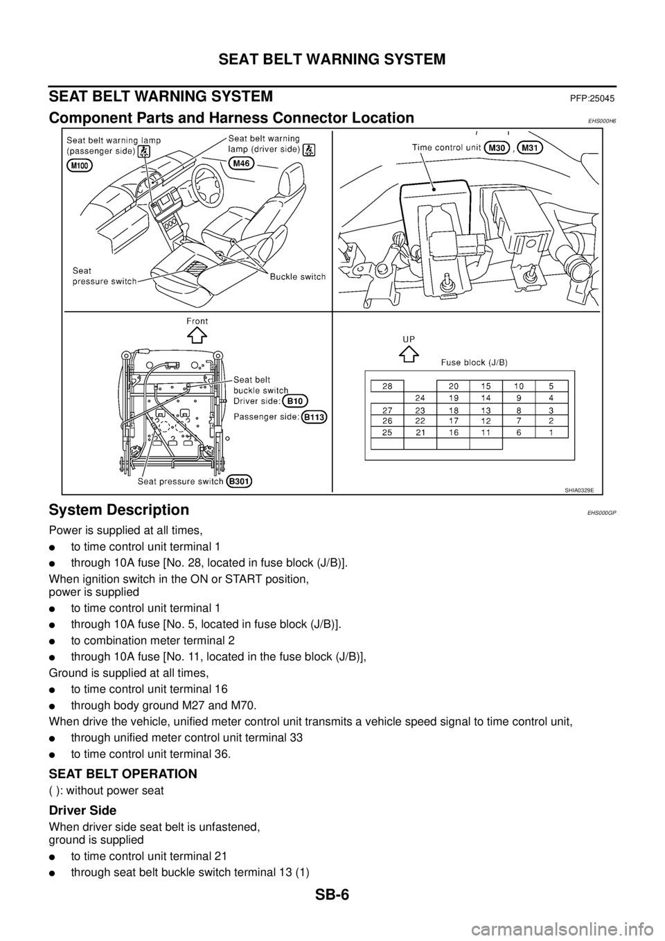
Component Parts and Harness Connector LocationEHS000H6
System DescriptionEHS000GP
Power is supplied at all times,
�to time control unit terminal 1
�through 10A fuse [No. 28, located in fuse block (J/B)].
When ignition switch in the ON or START position,
power is supplied
�to time control unit terminal 1
�through 10A fuse [No. 5, located in fuse block (J/B)].
�to combination meter terminal 2
�through 10A fuse [No. 11, located in the fuse block (J/B)],
Ground is supplied at all times,
�to time control unit terminal 16
�through body ground M27 and M70.
When drive the vehicle, unified meter control unit transmits a vehicle speed signal to time control unit,
�through unified meter control unit terminal 33
�to time control unit terminal 36.
SEAT BELT OPERATION
( ): without power seat
Driver Side
When driver side seat belt is unfastened,
ground is supplied
�to time control unit terminal 21
�through seat belt buckle switch terminal 13 (1)
SHIA0329E
Page 2995 of 4179
SEAT BELT WARNING SYSTEM
SB-15
C
D
E
F
G
I
J
K
L
MA
B
SB
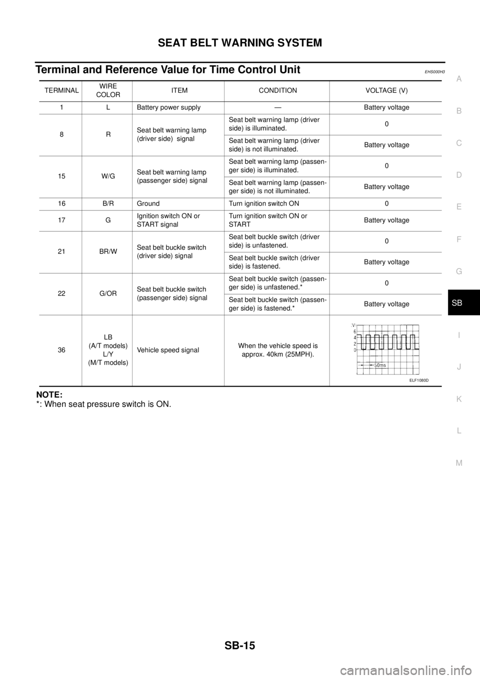
Terminal and Reference Value for Time Control Unit EHS000H3
NOTE:
*: When seat pressure switch is ON.
TERMINALWIRE
COLORITEM CONDITION VOLTAGE (V)
1 L Battery power supply — Battery voltage
8RSeat belt warning lamp
(driver side) signalSeat belt warning lamp (driver
side) is illuminated.0
Seat belt warning lamp (driver
side) is not illuminated.Battery voltage
15 W/GSeat belt warning lamp
(passenger side) signalSeat belt warning lamp (passen-
ger side) is illuminated.0
Seat belt warning lamp (passen-
ger side) is not illuminated.Battery voltage
16 B/R Ground Turn ignition switch ON 0
17 GIgnition switch ON or
START signalTurn ignition switch ON or
STARTBattery voltage
21 BR/WSeat belt buckle switch
(driver side) signalSeat belt buckle switch (driver
side) is unfastened.0
Seat belt buckle switch (driver
side) is fastened.Battery voltage
22 G/ORSeat belt buckle switch
(passenger side) signalSeat belt buckle switch (passen-
ger side) is unfastened.*0
Seat belt buckle switch (passen-
ger side) is fastened.*Battery voltage
36LB
(A/T models)
L/Y
(M/T models)Vehicle speed signal When the vehicle speed is
approx. 40km (25MPH).
ELF1080D
Page 3010 of 4179
SRS-6
SUPPLEMENTAL RESTRAINT SYSTEM (SRS)
SUPPLEMENTAL RESTRAINT SYSTEM (SRS)PFP:28556
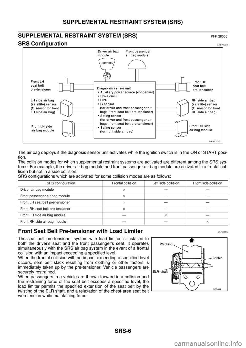
SRS ConfigurationEHS000CH
The air bag deploys if the diagnosis sensor unit activates while the ignition switch is in the ON or START posi-
tion.
The collision modes for which supplemental restraint systems are activated are different among the SRS sys-
tems. For example, the driver air bag module and front passenger air bag module are activated in a frontal col-
lision but not in a side collision.
SRS configurations which are activated for some collision modes are as follows;
Front Seat Belt Pre-tensioner with Load LimiterEHS000CI
The seat belt pre-tensioner system with load limiter is installed to
both the driver's seat and the front passenger's seat. It operates
simultaneously with the SRS air bag system in the event of a frontal
collision with an impact exceeding a specified level.
When the frontal collision with an impact exceeding a specified level
occurs, seat belt slack resulting from clothing or other factors is
immediately taken up by the pre-tensioner. Vehicle passengers are
securely restrained.
When passengers in a vehicle are thrown forward in a collision and
the restraining force of the seat belt exceeds a specified level, the
load limiter permits the specified extension of the seat belt by the
twisting of the ELR shaft, and a relaxation of the chest-area seat belt
web tension while maintaining force.
PHIA0037E
SRS configuration Frontal collision Left side collision Right side collision
Driver air bag module×——
Front passenger air bag module×——
Front LH seat belt pre-tensioner×——
Front RH seat belt pre-tensioner×——
Front LH side air bag module —×—
Front RH side air bag module — —×
SRS444
Page 3023 of 4179
TROUBLE DIAGNOSIS
SRS-19
C
D
E
F
G
I
J
K
L
MA
B
SRS
Trouble Diagnosis with CONSULT–IIEHS000O8
DIAGNOSTIC PROCEDURE 2
Inspecting SRS Malfunctioning Parts by Using CONSULT-II — DIAGNOSIS MODE
1. Turn ignition switch OFF.
2. Connect CONSULT-II to the data link connector.
3. Turn ignition switch ON.
4. Touch “START (NISSAN BASED VHCL)”.
5. Touch “AIR BAG”.
If “AIR BAG” is not indicated, GI-35, "
CONSULT-II Data Link
Connector (DLC) Circuit" .
6. On the “self-diagnosis mode selection” screen of CONSULT-II,
select the desired “self-diagnosis mode key”.
SIIA1249E
PHIA0157E
SRS771
SRS697
Page 3024 of 4179
![NISSAN X-TRAIL 2003 Service Repair Manual SRS-20
TROUBLE DIAGNOSIS
a. Touch “SELF-DIAG [CURRENT]”.
�Diagnostic code is displayed on “SELF-DIAG [CURRENT]”.
i. If the malfunction is displayed in the “SRS Operation Check” (Air bag NISSAN X-TRAIL 2003 Service Repair Manual SRS-20
TROUBLE DIAGNOSIS
a. Touch “SELF-DIAG [CURRENT]”.
�Diagnostic code is displayed on “SELF-DIAG [CURRENT]”.
i. If the malfunction is displayed in the “SRS Operation Check” (Air bag](/manual-img/5/57404/w960_57404-3023.png)
SRS-20
TROUBLE DIAGNOSIS
a. Touch “SELF-DIAG [CURRENT]”.
�Diagnostic code is displayed on “SELF-DIAG [CURRENT]”.
i. If the malfunction is displayed in the “SRS Operation Check” (Air bag warning lamp blinking) but no mal-
function is displayed in the “SELF-DIAG [CURRENT]”, the following possibilities shall be checked. Refer
to SRS-21, "
DIAGNOSTIC PROCEDURE 3" .
�Low battery voltage (Less than 9 V)
�After the malfunction part is repaired, the diagnosis results in “SELF-DIAG [PAST]” has not been
erased.
�An intermittent malfunction has been stored in the past.
NOTE:
Intermittent malfunction is a malfunction that has occurred once in the past, but soon recovered.
b. Touch “SELF-DIAG [PAST]”.
�The diagnostic code is displayed until erasing the memory in
the “SELF-DIAG [CURRENT]”.
c. Touch “TROUBLE DIAG RECORD”.
�The diagnosis results (malfunction parts stored in the diagno-
sis sensor unit) stored in the self-diagnosis results are dis-
played.
�The memory of “TROUBLE DIAG RECORD” cannot be
erased.
7. Each diagnostic code is displayed. Refer to SRS-22, "
Diagnostic
Code Chart" .
8. Touch “PRINT”, if required.
9. Based on each diagnosis result, repair or replace the malfunc-
tion parts.
CAUTION:
Be sure to start the work after the following steps. Turn the
ignition switch OFF, and disconnect both battery cables.
Then wait for at least 3 minutes.
SHIA0203E
SHIA0181E
SHIA0182E
SHIA0180E
Page 3032 of 4179
SRS-28
TROUBLE DIAGNOSIS
Trouble Diagnosis: “AIR BAG” Warning Lamp Does Not Turn OffEHS000OB
DIAGNOSTIC PROCEDURE 5
1. CHECK THE DEPLOYMENT OF AIR BAG MODULE
Is air bag module deployed?
YES or NO
YES >> Refer to SRS-48, "COLLISION DIAGNOSIS" .
NO >> GO TO 2.
2. CHECK THE AIR BAG FUSE
Check 10A fuse [No. 9, located in fuse block (J/B)].
Refer to PG-2, "
POWER SUPPLY ROUTING" .
OK or NG
OK >> GO TO 4.
NG >> GO TO 3.
3. CHECK AIR BAG FUSE AGAIN
Replace “AIR BAG” fuse and turn ignition switch ON.
Is
“AIR BAG” fuse blown again?
YES >> Repair main harness.
NO >>INSPECTION END
4. CHECK DIAGNOSIS SENSOR UNIT
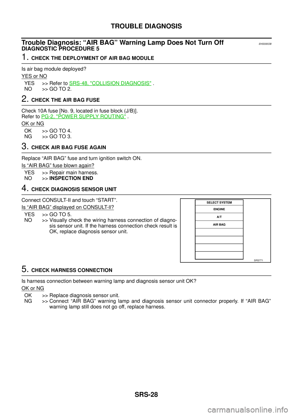
Connect CONSULT-II and touch “START”.
Is
“AIR BAG” displayed on CONSULT-ll?
YES >> GO TO 5.
NO >> Visually check the wiring harness connection of diagno-
sis sensor unit. If the harness connection check result is
OK, replace diagnosis sensor unit.
5. CHECK HARNESS CONNECTION
Is harness connection between warning lamp and diagnosis sensor unit OK?
OK or NG
OK >> Replace diagnosis sensor unit.
NG >> Connect “AIR BAG” warning lamp and diagnosis sensor unit connector properly. If “AIR BAG”
warning lamp still does not go off, replace harness.
SRS771