Page 3877 of 4179
CAN SYSTEM (TYPE 5)
LAN-99
[CAN]
C
D
E
F
G
H
I
J
L
MA
B
LAN
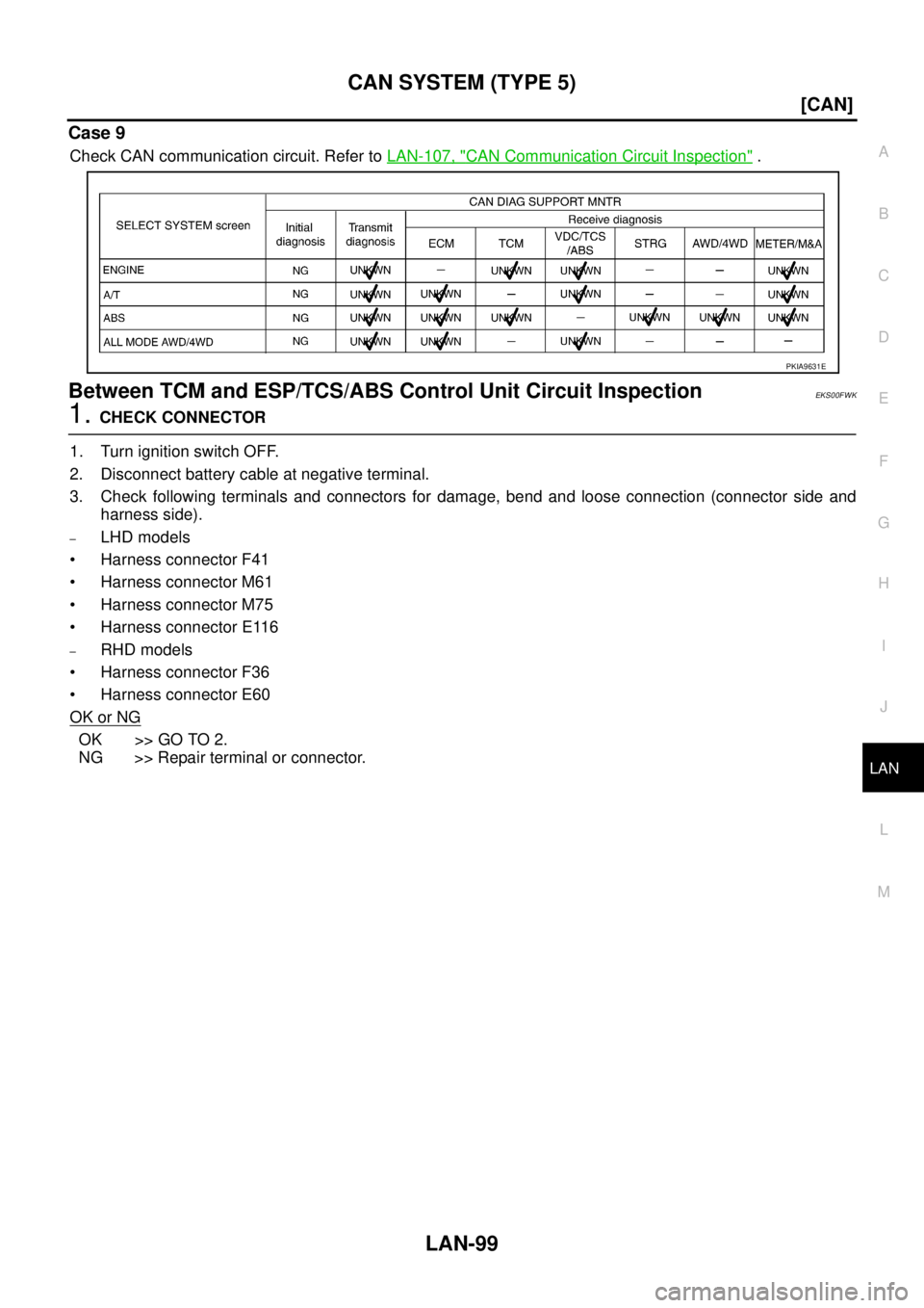
Case 9
Check CAN communication circuit. Refer to LAN-107, "CAN Communication Circuit Inspection" .
Between TCM and ESP/TCS/ABS Control Unit Circuit InspectionEKS00FWK
1. CHECK CONNECTOR
1. Turn ignition switch OFF.
2. Disconnect battery cable at negative terminal.
3. Check following terminals and connectors for damage, bend and loose connection (connector side and
harness side).
–LHD models
Harness connector F41
Harness connector M61
Harness connector M75
Harness connector E116
–RHD models
Harness connector F36
Harness connector E60
OK or NG
OK >> GO TO 2.
NG >> Repair terminal or connector.
PKIA9631E
Page 3879 of 4179
CAN SYSTEM (TYPE 5)
LAN-101
[CAN]
C
D
E
F
G
H
I
J
L
MA
B
LAN
3. CHECK HARNESS FOR OPEN CIRCUIT
1. Disconnect ESP/TCS/ABS control unit connector.
2. Check the following.
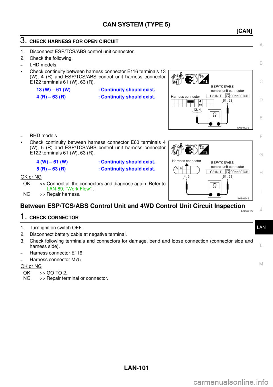
–LHD models
Check continuity between harness connector E116 terminals 13
(W), 4 (R) and ESP/TCS/ABS control unit harness connector
E122 terminals 61 (W), 63 (R).
–RHD models
Check continuity between harness connector E60 terminals 4
(W), 5 (R) and ESP/TCS/ABS control unit harness connector
E122 terminals 61 (W), 63 (R).
OK or NG
OK >> Connect all the connectors and diagnose again. Refer to
LAN-89, "
Work Flow" .
NG >> Repair harness.
Between ESP/TCS/ABS Control Unit and 4WD Control Unit Circuit InspectionEKS00FWL
1. CHECK CONNECTOR
1. Turn ignition switch OFF.
2. Disconnect battery cable at negative terminal.
3. Check following terminals and connectors for damage, bend and loose connection (connector side and
harness side).
–Harness connector E116
–Harness connector M75
OK or NG
OK >> GO TO 2.
NG >> Repair terminal or connector.13 (W) – 61 (W) : Continuity should exist.
4 (R) – 63 (R) : Continuity should exist.
SKIB0123E
4 (W) – 61 (W) : Continuity should exist.
5 (R) – 63 (R) : Continuity should exist.
SKIB0124E
Page 3881 of 4179
CAN SYSTEM (TYPE 5)
LAN-103
[CAN]
C
D
E
F
G
H
I
J
L
MA
B
LAN
3. CHECK HARNESS FOR OPEN CIRCUIT
1. Disconnect 4WD control unit connector.
2. Check the following.
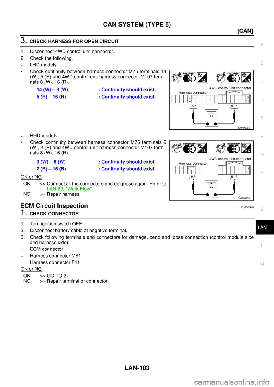
–LHD models
Check continuity between harness connector M75 terminals 14
(W), 5 (R) and 4WD control unit harness connector M107 termi-
nals 8 (W), 16 (R).
–RHD models
Check continuity between harness connector M75 terminals 9
(W), 2 (R) and 4WD control unit harness connector M107 termi-
nals 8 (W), 16 (R).
OK or NG
OK >> Connect all the connectors and diagnose again. Refer to
LAN-89, "
Work Flow" .
NG >> Repair harness.
ECM Circuit InspectionEKS00FWM
1. CHECK CONNECTOR
1. Turn ignition switch OFF.
2. Disconnect battery cable at negative terminal.
3. Check following terminals and connectors for damage, bend and loose connection (control module side
and harness side).
–ECM connector
–Harness connector M61
–Harness connector F41
OK or NG
OK >> GO TO 2.
NG >> Repair terminal or connector.14 (W) – 8 (W) : Continuity should exist.
5 (R) – 16 (R) : Continuity should exist.
SKIA9576E
9 (W) – 8 (W) : Continuity should exist.
2 (R) – 16 (R) : Continuity should exist.
SKIA9577E
Page 3882 of 4179
LAN-104
[CAN]
CAN SYSTEM (TYPE 5)
2. CHECK HARNESS FOR OPEN CIRCUIT
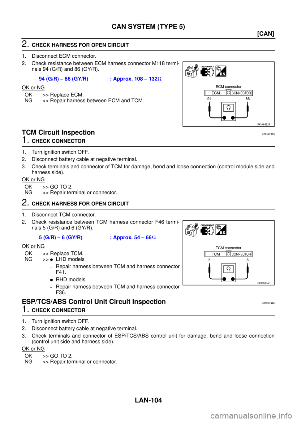
1. Disconnect ECM connector.
2. Check resistance between ECM harness connector M118 termi-
nals 94 (G/R) and 86 (GY/R).
OK or NG
OK >> Replace ECM.
NG >> Repair harness between ECM and TCM.
TCM Circuit InspectionEKS00FWN
1. CHECK CONNECTOR
1. Turn ignition switch OFF.
2. Disconnect battery cable at negative terminal.
3. Check terminals and connector of TCM for damage, bend and loose connection (control module side and
harness side).
OK or NG
OK >> GO TO 2.
NG >> Repair terminal or connector.
2. CHECK HARNESS FOR OPEN CIRCUIT
1. Disconnect TCM connector.
2. Check resistance between TCM harness connector F46 termi-
nals 5 (G/R) and 6 (GY/R).
OK or NG
OK >> Replace TCM.
NG >>
�LHD models
–Repair harness between TCM and harness connector
F41.
�RHD models
–Repair harness between TCM and harness connector
F36.
ESP/TCS/ABS Control Unit Circuit InspectionEKS00FWO
1. CHECK CONNECTOR
1. Turn ignition switch OFF.
2. Disconnect battery cable at negative terminal.
3. Check terminals and connector of ESP/TCS/ABS control unit for damage, bend and loose connection
(control unit side and harness side).
OK or NG
OK >> GO TO 2.
NG >> Repair terminal or connector.94 (G/R) – 86 (GY/R) : Approx. 108 – 132Ω
PKIA9592E
5 (G/R) – 6 (GY/R) : Approx. 54 – 66Ω
SKIB0094E
Page 3883 of 4179
CAN SYSTEM (TYPE 5)
LAN-105
[CAN]
C
D
E
F
G
H
I
J
L
MA
B
LAN
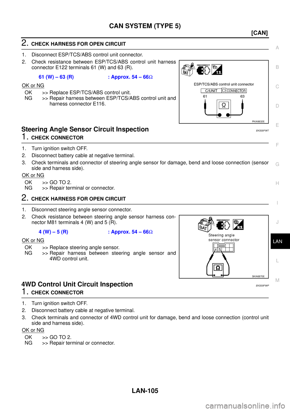
2. CHECK HARNESS FOR OPEN CIRCUIT
1. Disconnect ESP/TCS/ABS control unit connector.
2. Check resistance between ESP/TCS/ABS control unit harness
connector E122 terminals 61 (W) and 63 (R).
OK or NG
OK >> Replace ESP/TCS/ABS control unit.
NG >> Repair harness between ESP/TCS/ABS control unit and
harness connector E116.
Steering Angle Sensor Circuit InspectionEKS00FWT
1. CHECK CONNECTOR
1. Turn ignition switch OFF.
2. Disconnect battery cable at negative terminal.
3. Check terminals and connector of steering angle sensor for damage, bend and loose connection (sensor
side and harness side).
OK or NG
OK >> GO TO 2.
NG >> Repair terminal or connector.
2. CHECK HARNESS FOR OPEN CIRCUIT
1. Disconnect steering angle sensor connector.
2. Check resistance between steering angle sensor harness con-
nector M81 terminals 4 (W) and 5 (R).
OK or NG
OK >> Replace steering angle sensor.
NG >> Repair harness between steering angle sensor and
4WD control unit.
4WD Control Unit Circuit InspectionEKS00FWP
1. CHECK CONNECTOR
1. Turn ignition switch OFF.
2. Disconnect battery cable at negative terminal.
3. Check terminals and connector of 4WD control unit for damage, bend and loose connection (control unit
side and harness side).
OK or NG
OK >> GO TO 2.
NG >> Repair terminal or connector.61 (W) – 63 (R) : Approx. 54 – 66Ω
PKIA9632E
4 (W) – 5 (R) : Approx. 54 – 66Ω
SKIA6870E
Page 3884 of 4179
LAN-106
[CAN]
CAN SYSTEM (TYPE 5)
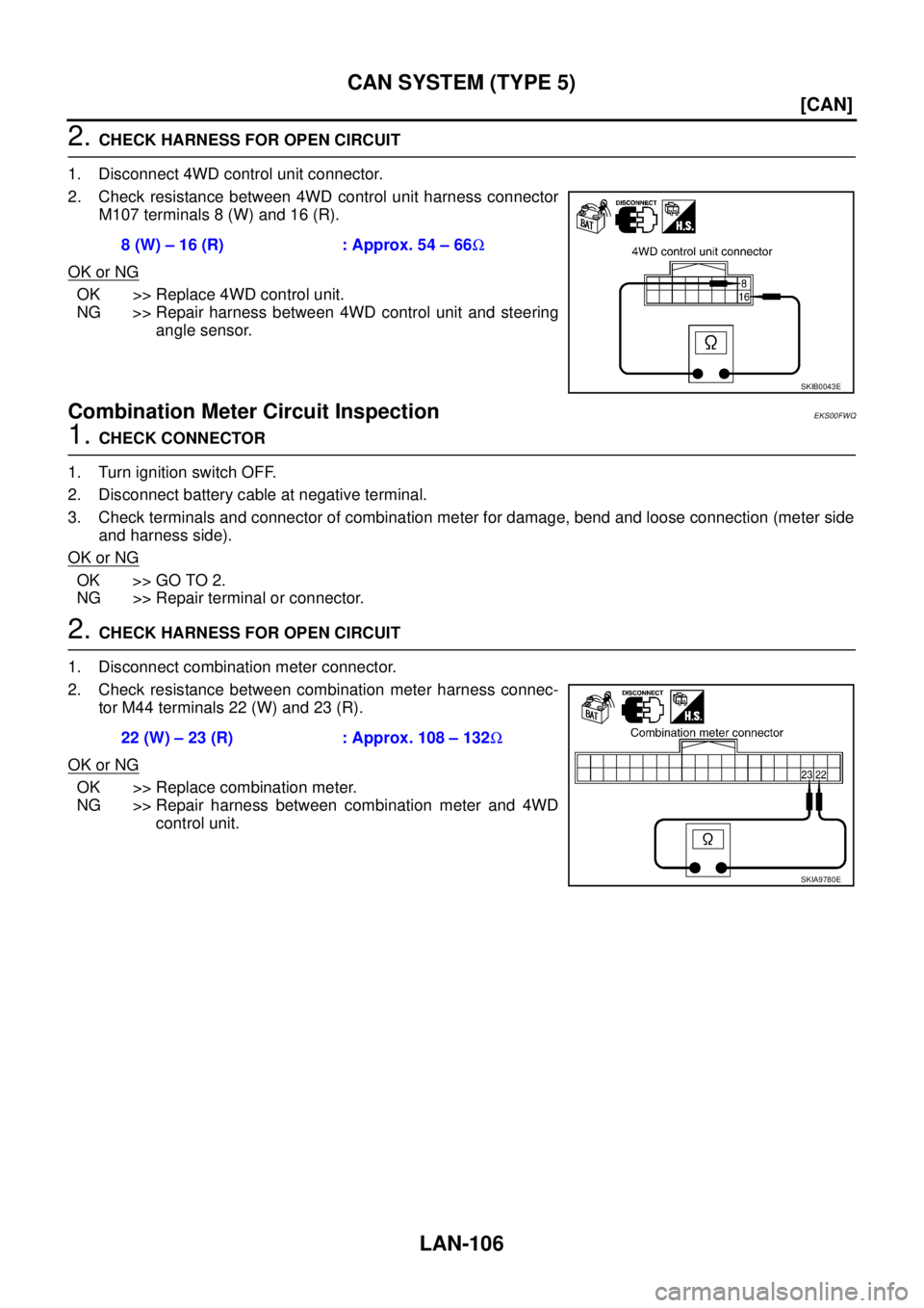
2. CHECK HARNESS FOR OPEN CIRCUIT
1. Disconnect 4WD control unit connector.
2. Check resistance between 4WD control unit harness connector
M107 terminals 8 (W) and 16 (R).
OK or NG
OK >> Replace 4WD control unit.
NG >> Repair harness between 4WD control unit and steering
angle sensor.
Combination Meter Circuit InspectionEKS00FWQ
1. CHECK CONNECTOR
1. Turn ignition switch OFF.
2. Disconnect battery cable at negative terminal.
3. Check terminals and connector of combination meter for damage, bend and loose connection (meter side
and harness side).
OK or NG
OK >> GO TO 2.
NG >> Repair terminal or connector.
2. CHECK HARNESS FOR OPEN CIRCUIT
1. Disconnect combination meter connector.
2. Check resistance between combination meter harness connec-
tor M44 terminals 22 (W) and 23 (R).
OK or NG
OK >> Replace combination meter.
NG >> Repair harness between combination meter and 4WD
control unit. 8 (W) – 16 (R) : Approx. 54 – 66Ω
SKIB0043E
22 (W) – 23 (R) : Approx. 108 – 132Ω
SKIA9780E
Page 3885 of 4179
CAN SYSTEM (TYPE 5)
LAN-107
[CAN]
C
D
E
F
G
H
I
J
L
MA
B
LAN
CAN Communication Circuit InspectionEKS00FWR
1. CHECK CONNECTOR
1. Turn ignition switch OFF.
2. Disconnect battery cable at negative terminal.
3. Check following terminals and connectors for damage, bend and loose connection (control module side,
control unit side, sensor side, meter side, connector side and harness side).
–ECM
–TCM
–ESP/TCS/ABS control unit
–Steering angle sensor
–4WD control unit
–Combination meter
–Between ECM and combination meter
OK or NG
OK >> GO TO 2.
NG >> Repair terminal or connector.
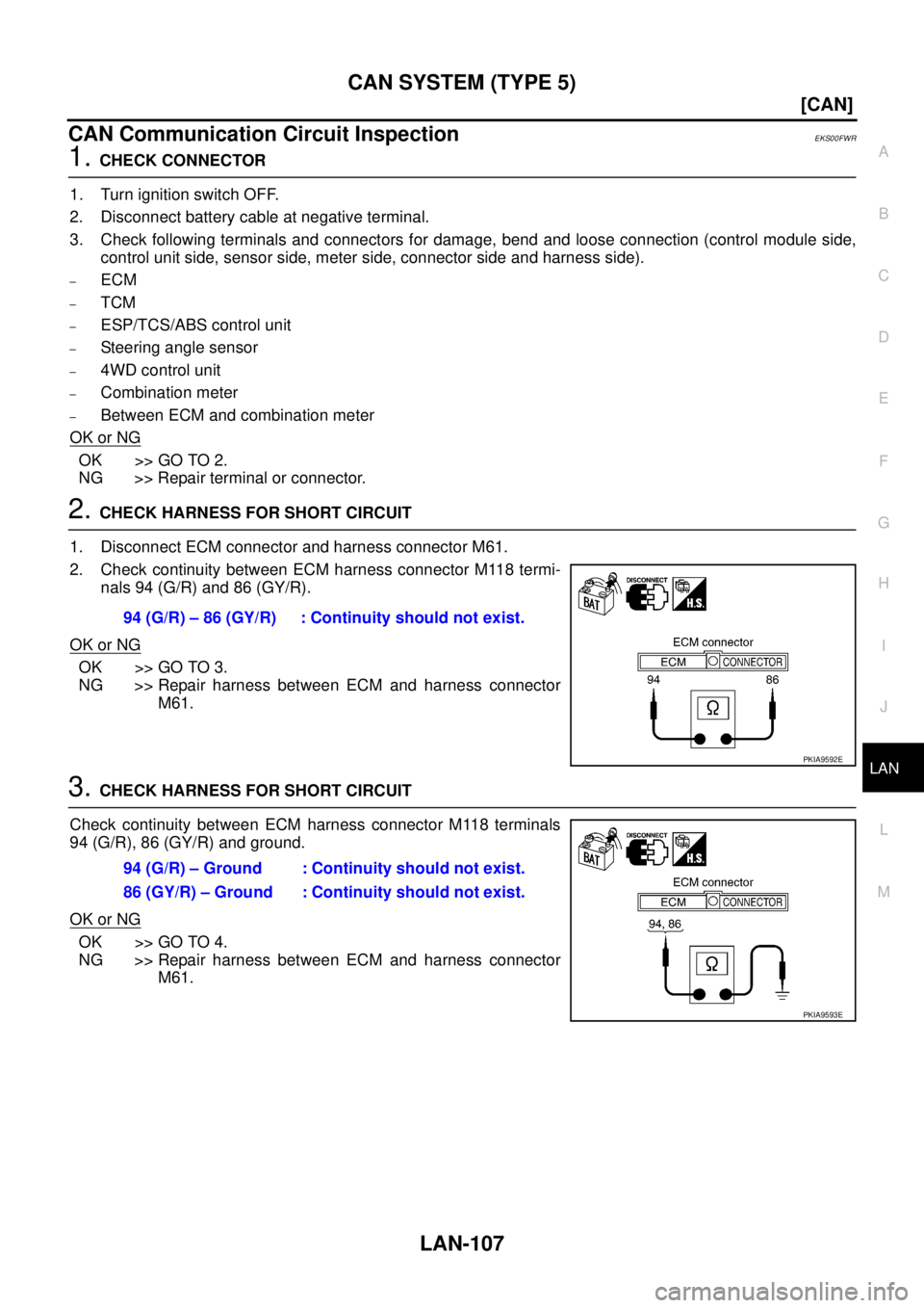
2. CHECK HARNESS FOR SHORT CIRCUIT
1. Disconnect ECM connector and harness connector M61.
2. Check continuity between ECM harness connector M118 termi-
nals 94 (G/R) and 86 (GY/R).
OK or NG
OK >> GO TO 3.
NG >> Repair harness between ECM and harness connector
M61.
3. CHECK HARNESS FOR SHORT CIRCUIT
Check continuity between ECM harness connector M118 terminals
94 (G/R), 86 (GY/R) and ground.
OK or NG
OK >> GO TO 4.
NG >> Repair harness between ECM and harness connector
M61. 94 (G/R) – 86 (GY/R) : Continuity should not exist.
PKIA9592E
94 (G/R) – Ground : Continuity should not exist.
86 (GY/R) – Ground : Continuity should not exist.
PKIA9593E
Page 3896 of 4179
AV-6
AUDIO
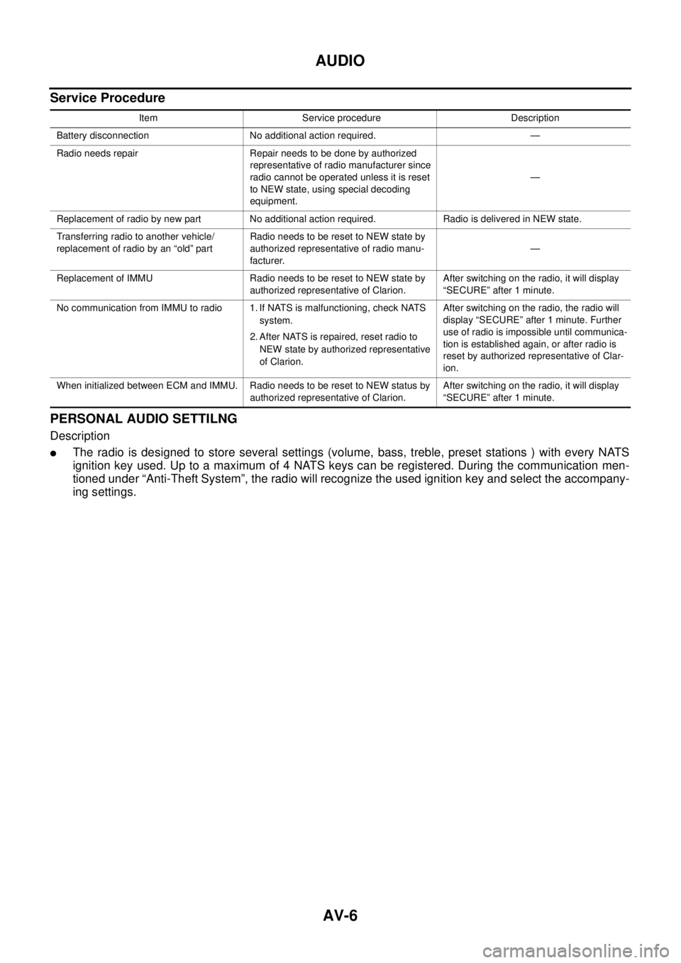
Service Procedure
PERSONAL AUDIO SETTILNG
Description
�The radio is designed to store several settings (volume, bass, treble, preset stations ) with every NATS
ignition key used. Up to a maximum of 4 NATS keys can be registered. During the communication men-
tioned under “Anti-Theft System”, the radio will recognize the used ignition key and select the accompany-
ing settings.
Item Service procedure Description
Battery disconnection No additional action required. —
Radio needs repair Repair needs to be done by authorized
representative of radio manufacturer since
radio cannot be operated unless it is reset
to NEW state, using special decoding
equipment.—
Replacement of radio by new part No additional action required. Radio is delivered in NEW state.
Transferring radio to another vehicle/
replacement of radio by an “old” partRadio needs to be reset to NEW state by
authorized representative of radio manu-
facturer.—
Replacement of IMMU Radio needs to be reset to NEW state by
authorized representative of Clarion.After switching on the radio, it will display
“SECURE” after 1 minute.
No communication from IMMU to radio 1. If NATS is malfunctioning, check NATS
system.
2. After NATS is repaired, reset radio to
NEW state by authorized representative
of Clarion.After switching on the radio, the radio will
display “SECURE” after 1 minute. Further
use of radio is impossible until communica-
tion is established again, or after radio is
reset by authorized representative of Clar-
ion.
When initialized between ECM and IMMU. Radio needs to be reset to NEW status by
authorized representative of Clarion.After switching on the radio, it will display
“SECURE” after 1 minute.