Page 3609 of 4179
MTC-1
MANUAL AIR CONDITIONER
J AIR CONDITIONER
CONTENTS
C
D
E
F
G
H
I
K
L
M
SECTION
A
B
MTC
MANUAL AIR CONDITIONER
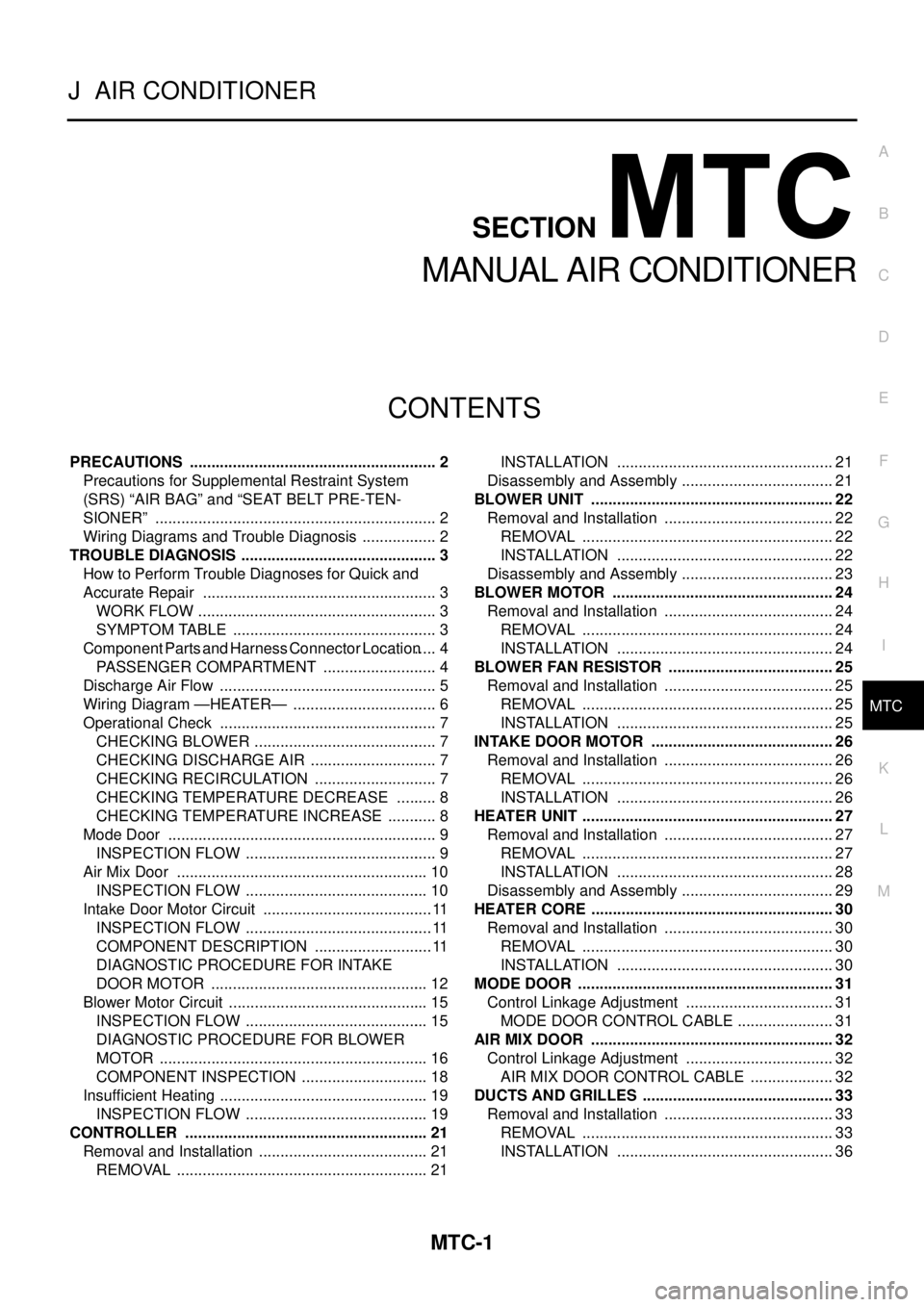
PRECAUTIONS .......................................................... 2
Precautions for Supplemental Restraint System
(SRS) “AIR BAG” and “SEAT BELT PRE-TEN-
SIONER” .................................................................. 2
Wiring Diagrams and Trouble Diagnosis .................. 2
TROUBLE DIAGNOSIS .............................................. 3
How to Perform Trouble Diagnoses for Quick and
Accurate Repair ....................................................... 3
WORK FLOW ........................................................ 3
SYMPTOM TABLE ................................................ 3
Component Parts and Harness Connector Location ..... 4
PASSENGER COMPARTMENT ........................... 4
Discharge Air Flow ................................................... 5
Wiring Diagram —HEATER— .................................. 6
Operational Check ................................................... 7
CHECKING BLOWER ........................................... 7
CHECKING DISCHARGE AIR .............................. 7
CHECKING RECIRCULATION ............................. 7
CHECKING TEMPERATURE DECREASE .......... 8
CHECKING TEMPERATURE INCREASE ............ 8
Mode Door ............................................................... 9
INSPECTION FLOW ............................................. 9
Air Mix Door ........................................................... 10
INSPECTION FLOW ........................................... 10
Intake Door Motor Circuit ........................................ 11
INSPECTION FLOW ............................................ 11
COMPONENT DESCRIPTION ............................ 11
DIAGNOSTIC PROCEDURE FOR INTAKE
DOOR MOTOR ................................................... 12
Blower Motor Circuit ............................................... 15
INSPECTION FLOW ........................................... 15
DIAGNOSTIC PROCEDURE FOR BLOWER
MOTOR ............................................................... 16
COMPONENT INSPECTION .............................. 18
Insufficient Heating ................................................. 19
INSPECTION FLOW ........................................... 19
CONTROLLER ......................................................... 21
Removal and Installation ........................................ 21
REMOVAL ........................................................... 21INSTALLATION ................................................... 21
Disassembly and Assembly .................................... 21
BLOWER UNIT ......................................................... 22
Removal and Installation ........................................ 22
REMOVAL ........................................................... 22
INSTALLATION ................................................... 22
Disassembly and Assembly .................................... 23
BLOWER MOTOR .................................................... 24
Removal and Installation ........................................ 24
REMOVAL ........................................................... 24
INSTALLATION ................................................... 24
BLOWER FAN RESISTOR ....................................... 25
Removal and Installation ........................................ 25
REMOVAL ........................................................... 25
INSTALLATION ................................................... 25
INTAKE DOOR MOTOR ........................................... 26
Removal and Installation ........................................ 26
REMOVAL ........................................................... 26
INSTALLATION ................................................... 26
HEATER UNIT ........................................................... 27
Removal and Installation ........................................ 27
REMOVAL ........................................................... 27
INSTALLATION ................................................... 28
Disassembly and Assembly .................................... 29
HEATER CORE ......................................................... 30
Removal and Installation ........................................ 30
REMOVAL ........................................................... 30
INSTALLATION ................................................... 30
MODE DOOR ............................................................ 31
Control Linkage Adjustment ................................... 31
MODE DOOR CONTROL CABLE ....................... 31
AIR MIX DOOR ......................................................... 32
Control Linkage Adjustment ................................... 32
AIR MIX DOOR CONTROL CABLE .................... 32
DUCTS AND GRILLES ............................................. 33
Removal and Installation ........................................ 33
REMOVAL ........................................................... 33
INSTALLATION ................................................... 36
Page 3611 of 4179
TROUBLE DIAGNOSIS
MTC-3
C
D
E
F
G
H
I
K
L
MA
B
MTC
TROUBLE DIAGNOSISPFP:00004
How to Perform Trouble Diagnoses for Quick and Accurate RepairEJS001FB
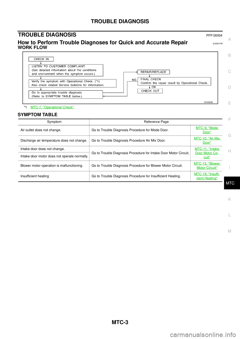
WORK FLOW
SYMPTOM TABLE
*1MTC-7, "Operational Check".
SHA900E
Symptom Reference Page
Air outlet does not change. Go to Trouble Diagnosis Procedure for Mode Door.MTC-9, "
Mode
Door"
Discharge air temperature does not change. Go to Trouble Diagnosis Procedure Air Mix Door.MTC-10, "Air Mix
Door"
Intake door does not change.
Go to Trouble Diagnosis Procedure for Intake Door Motor Circuit.MTC-11, "Intake
Door Motor Cir-
cuit"Intake door motor does not operate normally.
Blower motor operation is malfunctioning. Go to Trouble Diagnosis Procedure for Blower Motor Circuit.MTC-15, "
Blower
Motor Circuit"
Insufficient heating Go to Trouble Diagnosis Procedure for Insufficient Heating.MTC-19, "Insuffi-
cient Heating"
Page 3616 of 4179
MTC-8
TROUBLE DIAGNOSIS
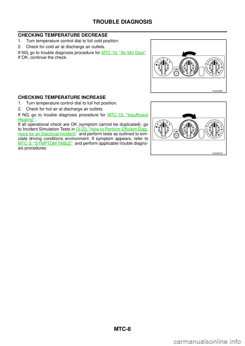
CHECKING TEMPERATURE DECREASE
1. Turn temperature control dial to full cold position.
2. Check for cold air at discharge air outlets.
If NG, go to trouble diagnosis procedure for MTC-10, "
Air Mix Door"
If OK, continue the check.
CHECKING TEMPERATURE INCREASE
1. Turn temperature control dial to full hot position.
2. Check for hot air at discharge air outlets.
If NG, go to trouble diagnosis procedure for MTC-19, "
Insufficient
Heating" .
If all operational check are OK (symptom cannot be duplicated), go
to Incident Simulation Tests in GI-23, "
How to Perform Efficient Diag-
nosis for an Electrical Incident" and perform tests as outlined to sim-
ulate driving conditions environment. If symptom appears, refer to
MTC-3, "
SYMPTOM TABLE" and perform applicable trouble diagno-
sis procedures.
RJIA0590E
RJIA0591E
Page 3627 of 4179
TROUBLE DIAGNOSIS
MTC-19
C
D
E
F
G
H
I
K
L
MA
B
MTC
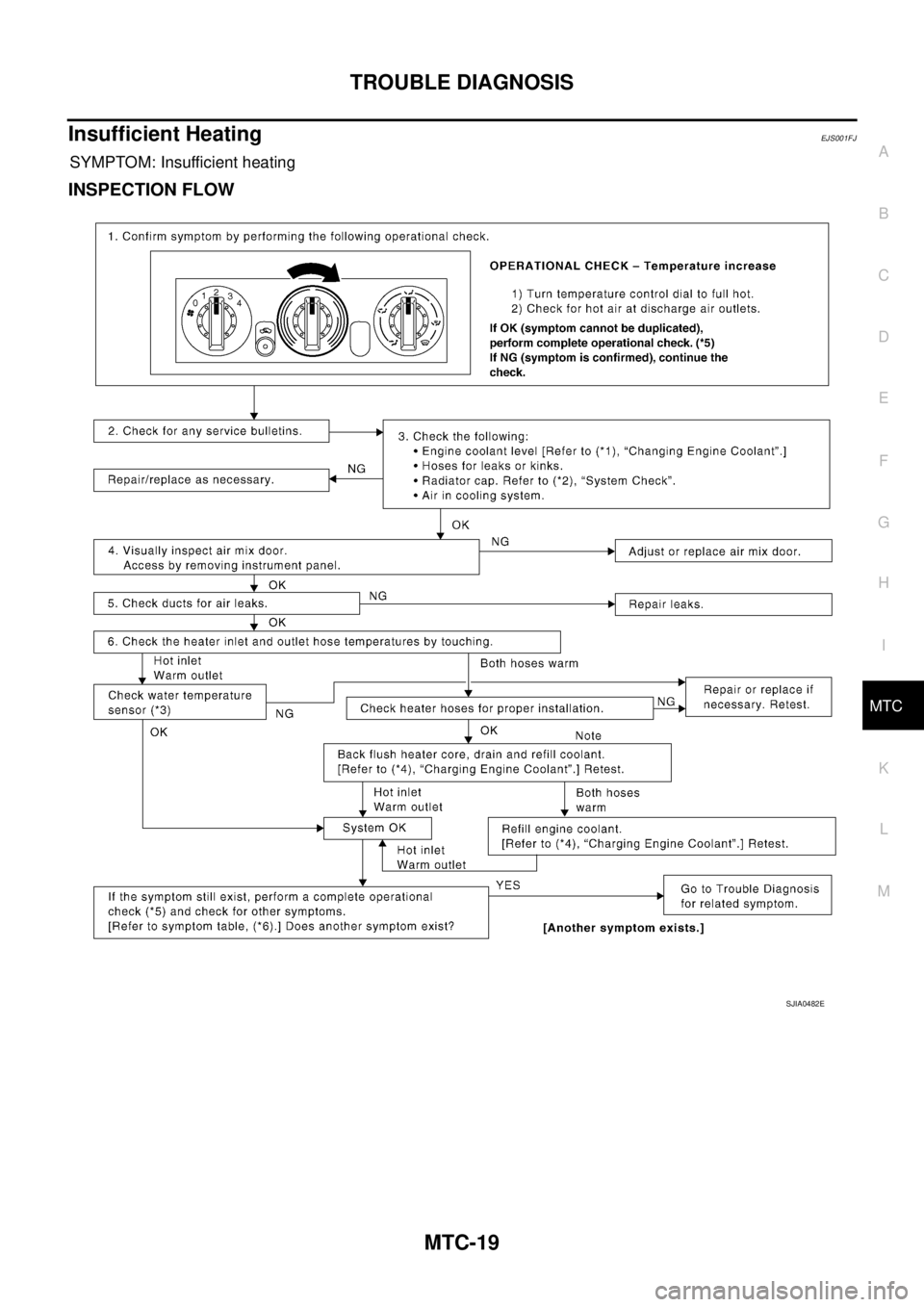
Insufficient HeatingEJS001FJ
SYMPTOM: Insufficient heating
INSPECTION FLOW
SJIA0482E