Page 3152 of 4179

BL-98
REAR DOOR LOCK
Disassembly and AssemblyEIS009QV
DISASSEMBLY
NOTE:
The door lock actuator must be removed and installed with the door lock assembly off the vehicle.
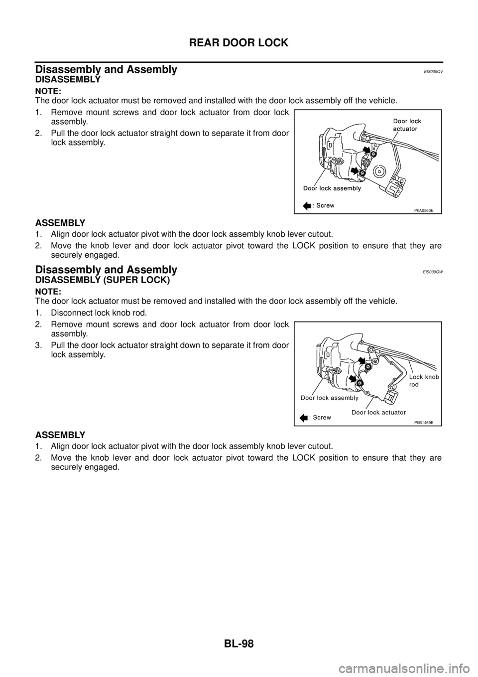
1. Remove mount screws and door lock actuator from door lock
assembly.
2. Pull the door lock actuator straight down to separate it from door
lock assembly.
ASSEMBLY
1. Align door lock actuator pivot with the door lock assembly knob lever cutout.
2. Move the knob lever and door lock actuator pivot toward the LOCK position to ensure that they are
securely engaged.
Disassembly and AssemblyEIS009QW
DISASSEMBLY (SUPER LOCK)
NOTE:
The door lock actuator must be removed and installed with the door lock assembly off the vehicle.
1. Disconnect lock knob rod.
2. Remove mount screws and door lock actuator from door lock
assembly.
3. Pull the door lock actuator straight down to separate it from door
lock assembly.
ASSEMBLY
1. Align door lock actuator pivot with the door lock assembly knob lever cutout.
2. Move the knob lever and door lock actuator pivot toward the LOCK position to ensure that they are
securely engaged.
PIIA0560E
PIIB1469E
Page 3267 of 4179

FRONT DOOR GLASS AND REGULATOR
GW-81
C
D
E
F
G
H
J
K
L
MA
B
GW
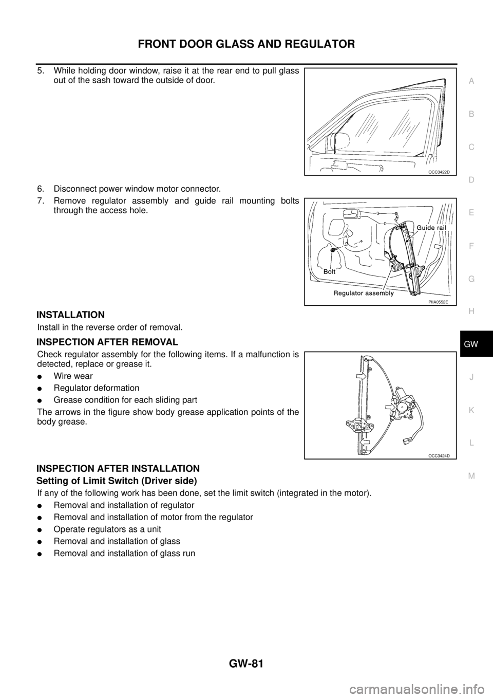
5. While holding door window, raise it at the rear end to pull glass
out of the sash toward the outside of door.
6. Disconnect power window motor connector.
7. Remove regulator assembly and guide rail mounting bolts
through the access hole.
INSTALLATION
Install in the reverse order of removal.
INSPECTION AFTER REMOVAL
Check regulator assembly for the following items. If a malfunction is
detected, replace or grease it.
�Wire wear
�Regulator deformation
�Grease condition for each sliding part
The arrows in the figure show body grease application points of the
body grease.
INSPECTION AFTER INSTALLATION
Setting of Limit Switch (Driver side)
If any of the following work has been done, set the limit switch (integrated in the motor).
�Removal and installation of regulator
�Removal and installation of motor from the regulator
�Operate regulators as a unit
�Removal and installation of glass
�Removal and installation of glass run
OCC3422D
PIIA0552E
OCC3424D
Page 3270 of 4179
GW-84
REAR DOOR GLASS AND REGULATOR
6. Using a slotted screwdriver or similar tool, remove clip on the
corner inner cover. Slide upper hook to remove, and remove the
cover.
7. Slide the corner inner cover sash cover forward to remove.
8. Remove corner outer cover mounting bolts. Disconnect upper
hook, and remove the cover.
9. Remove mounting nuts on upper portion of rear lower sash.
10. Remove mounting bolts from lower portion of rear lower sash.
11. Rotate rear lower sash, and remove door window from glass
run.
12. Pull out the door window toward the outside of the door to
remove.
13. Remove glass run from rear lower sash.
14. Remove rear lower sash.
15. Disconnect power window motor connector.
SIIA0132E
SIIA0140E
SIIA0133E
SIIA0134E
Page 3290 of 4179

RF-10
SUNROOF
SUNROOFPFP:91210
System DescriptionEIS000MK
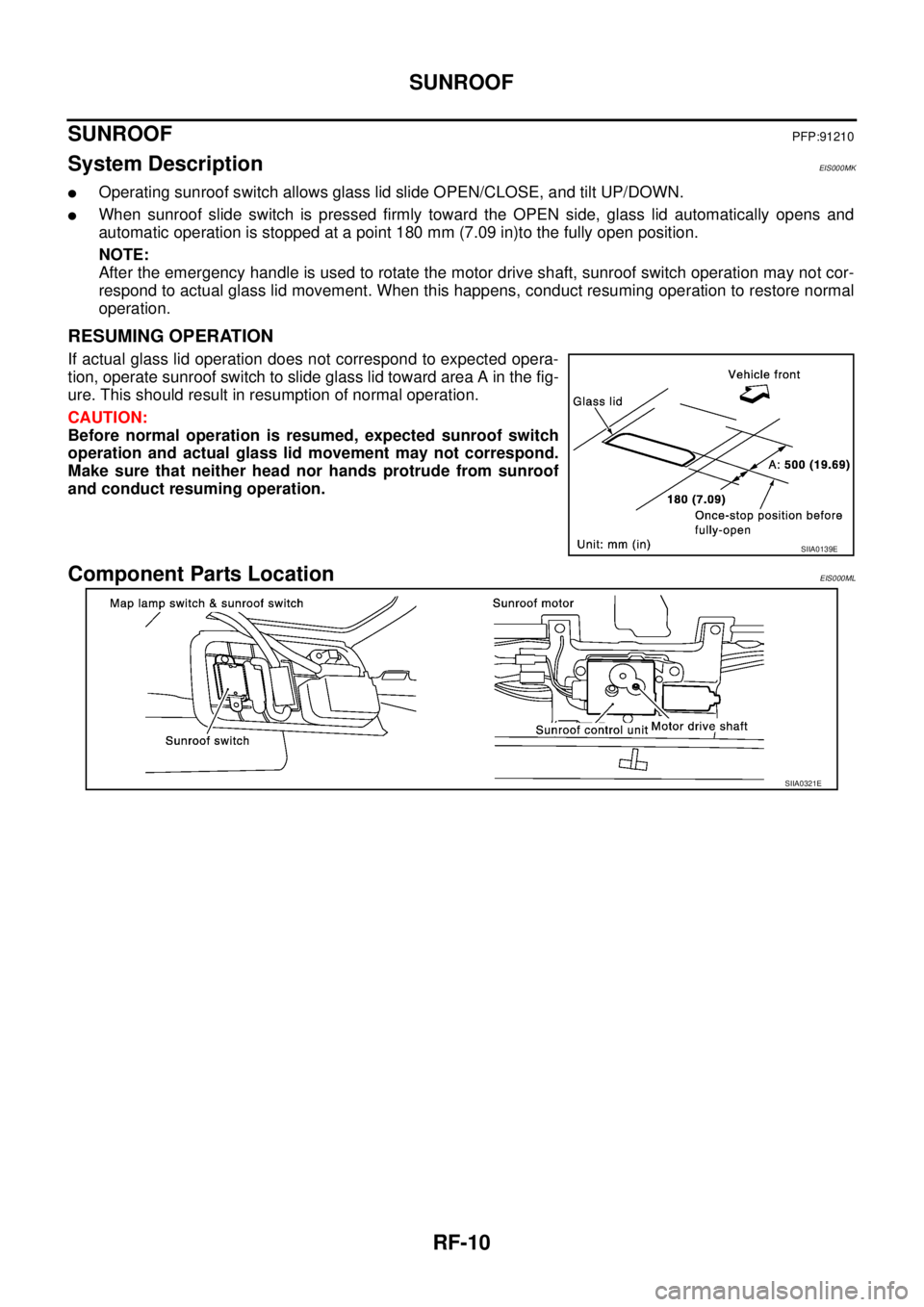
�Operating sunroof switch allows glass lid slide OPEN/CLOSE, and tilt UP/DOWN.
�When sunroof slide switch is pressed firmly toward the OPEN side, glass lid automatically opens and
automatic operation is stopped at a point 180 mm (7.09 in)to the fully open position.
NOTE:
After the emergency handle is used to rotate the motor drive shaft, sunroof switch operation may not cor-
respond to actual glass lid movement. When this happens, conduct resuming operation to restore normal
operation.
RESUMING OPERATION
If actual glass lid operation does not correspond to expected opera-
tion, operate sunroof switch to slide glass lid toward area A in the fig-
ure. This should result in resumption of normal operation.
CAUTION:
Before normal operation is resumed, expected sunroof switch
operation and actual glass lid movement may not correspond.
Make sure that neither head nor hands protrude from sunroof
and conduct resuming operation.
Component Parts LocationEIS000ML
SIIA0139E
SIIA0321E
Page 3298 of 4179

RF-18
SUNROOF
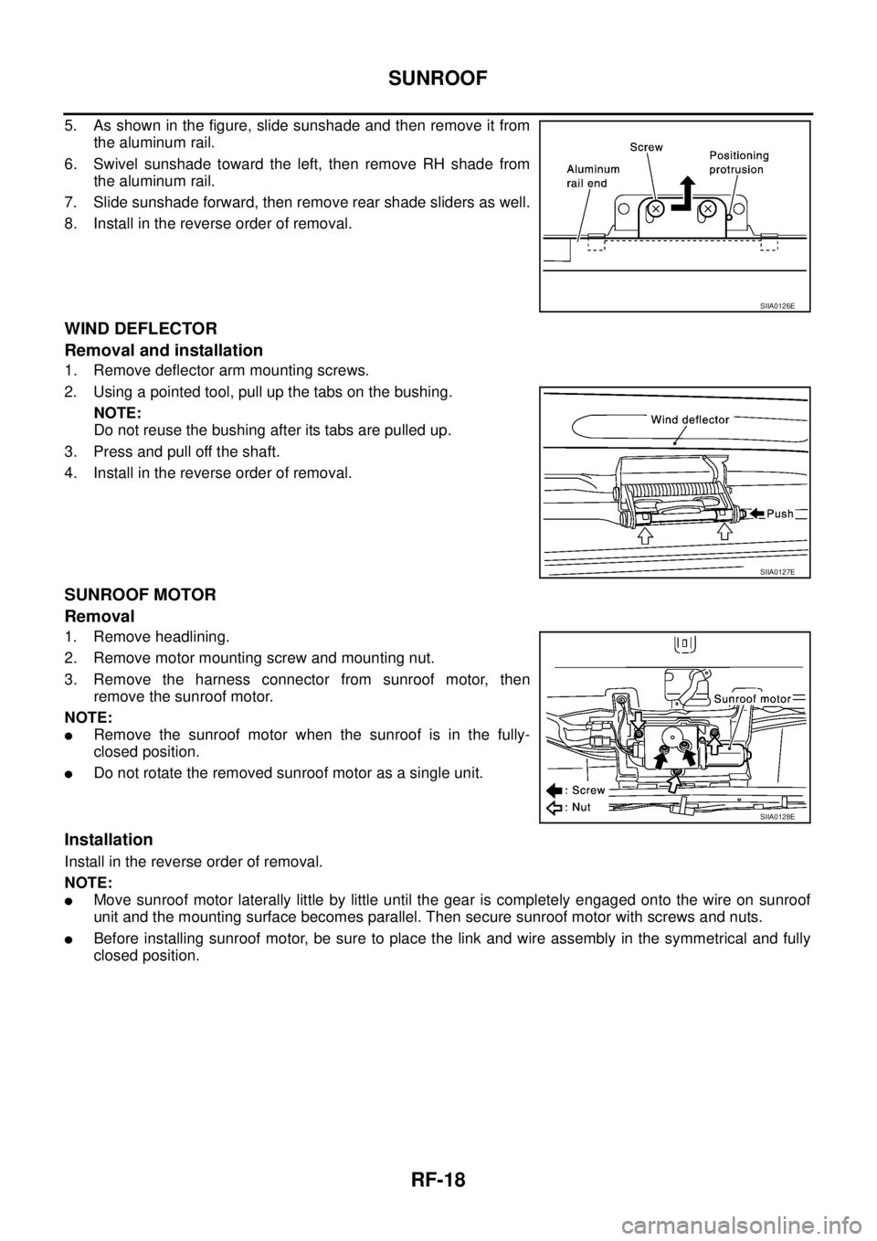
5. As shown in the figure, slide sunshade and then remove it from
the aluminum rail.
6. Swivel sunshade toward the left, then remove RH shade from
the aluminum rail.
7. Slide sunshade forward, then remove rear shade sliders as well.
8. Install in the reverse order of removal.
WIND DEFLECTOR
Removal and installation
1. Remove deflector arm mounting screws.
2. Using a pointed tool, pull up the tabs on the bushing.
NOTE:
Do not reuse the bushing after its tabs are pulled up.
3. Press and pull off the shaft.
4. Install in the reverse order of removal.
SUNROOF MOTOR
Removal
1. Remove headlining.
2. Remove motor mounting screw and mounting nut.
3. Remove the harness connector from sunroof motor, then
remove the sunroof motor.
NOTE:
�Remove the sunroof motor when the sunroof is in the fully-
closed position.
�Do not rotate the removed sunroof motor as a single unit.
Installation
Install in the reverse order of removal.
NOTE:
�Move sunroof motor laterally little by little until the gear is completely engaged onto the wire on sunroof
unit and the mounting surface becomes parallel. Then secure sunroof motor with screws and nuts.
�Before installing sunroof motor, be sure to place the link and wire assembly in the symmetrical and fully
closed position.
SIIA0126E
SIIA0127E
SIIA0128E
Page 3315 of 4179
REAR BUMPER
EI-17
C
D
E
F
G
H
J
K
L
MA
B
EI
REAR BUMPERPFP:H5022
Removal and InstallationEIS000MY
Bumper fascia is made of resin. Do not apply strong force to it, and be careful to prevent contact with oil.
REMOVAL
1. Remove mounting nuts on rear bumper protector.
2. Remove RH/LH chipping protector.
3. Remove mounting screws on RH/LH rear fender protector.
4. Remove mounting bolts and clips on rear bumper fascia.
5. Spread bumper fascia toward the outside and remove it from the side clips.
1. Rear bumper fascia 2. Reflector 3. Chipping protector
4. Bumper stay 5. Rear bumper energy absorber 6. Rear bumper protector
7. Rear bumper finisher 8. Rear fog lamp
PIIB0590E
Page 3355 of 4179
INSTRUMENT PANEL ASSEMBLY
IP-17
C
D
E
F
G
H
J
K
L
MA
B
IP
Glove Box Cover
1. Remove screw.
2. Remove relay clamp installed to back of glove box cover.
3. Pull it forward to remove.
Upper Glove Box
Disengage pawls and clips, and then pull it straight forward.
Passenger Air Bag Module
Remove passenger air bag module after removing bolts. Refer to SRS-35, "FRONT PASSENGER AIR BAG
MODULE" in SRS section.
Instrument Mask
Insert a screwdriver wrapped with a shop cloth into cutout on instrument mask. Disengage tab to remove.
Front Pillar Garnish
Pull straight front pillar garnish toward vehicle inside of right and left. Remove metal clip to remove.
Refer to EI-35, "
Removal and Installation" in EI section.
Instrument Panel
1. Remove nuts, and lower steering column.
PIIA9909E
PIIA9910E
SIIA0040E
Page 3521 of 4179
BLOWER UNIT
ATC-125
C
D
E
F
G
H
I
K
L
MA
B
AT C
BLOWER UNITPFP:27200
Removal and InstallationEJS000UL
REMOVAL
1. Remove glove box assembly.
2. Remove glove box cover, instrument passenger lower panel and
instrument reinforcement. Refer to IP-11, "
Removal and Installa-
tion" .
3. Remove ECM with ECM bracket attached.
4. Remove instrument panel mounting screw.
5. Remove blower unit mounting bolt and screws.
6. Disconnect blower motor connector and fan control amp. con-
nector.
7. Disconnect intake door motor connector and harness clip.
8. Remove blower unit.
CAUTION:
Slide the blower unit toward the right, remove location pins
(2 pieces), and then move it downward.
INSTALLATION
Installation is basically the reverse order of removal.
CAUTION:
Make sure location pins (2 pieces) are securely installed.
RJIA0052E
RJIA0098E