Page 205 of 4179
![NISSAN X-TRAIL 2003 Service Repair Manual VACUUM PUMP
EM-153
[YD22DDTi]
C
D
E
F
G
H
I
J
K
L
MA
EM
VACUUM PUMPPFP:41920
Removal and InstallationEBS00LRM
INSPECTION BEFORE REMOVAL
1. Disconnect vacuum hose, and connect a vacuum gauge via 3-wa](/manual-img/5/57404/w960_57404-204.png "NISSAN X-TRAIL 2003 Service Repair Manual VACUUM PUMP
EM-153
[YD22DDTi]
C
D
E
F
G
H
I
J
K
L
MA
EM
VACUUM PUMPPFP:41920
Removal and InstallationEBS00LRM
INSPECTION BEFORE REMOVAL
1. Disconnect vacuum hose, and connect a vacuum gauge via 3-wa")
VACUUM PUMP
EM-153
[YD22DDTi]
C
D
E
F
G
H
I
J
K
L
MA
EM
VACUUM PUMPPFP:41920
Removal and InstallationEBS00LRM
INSPECTION BEFORE REMOVAL
1. Disconnect vacuum hose, and connect a vacuum gauge via 3-way connector.
�Disconnect point where vacuum from vacuum pump can be measured directly and install 3-way con-
nector.
2. Start engine and measure generated vacuum at idle speed.
�If out of standard, check for air suction in vacuum route, and measure again.
�If still outside of standard, replace vacuum pump.
REMOVAL
1. Drain engine coolant. Refer to CO-31, "Changing Engine Coolant" .
2. Remove air duct and air cleaner case. Refer to EM-133, "
Removal and Installation" .
3. Remove charge air cooler. Refer to EM-135, "
Removal and Installation" .
4. Disconnect harness connector from fuel injector.
5. Remove injection tubes. Refer to EM-157, "
Removal and Installation" .
6. Remove rocker cover. Refer to EM-168, "
Removal and Installation" .
7. Remove spill tube. Refer to EM-157, "
Removal and Installation" .
8. Remove nozzle support from No. 2 cylinder and No. 2 fuel injector. Refer to EM-157, "
Removal and Instal-
lation" . (To fix the hexagonal portion of the camshaft.)
9. Remove air inlet pipes. Refer to EM-141, "
Removal and Installation" .
1.Vacuum pump and cylinder head rear cover
assembly2. O-ring 3. Cylinder head rear cover plate
4. Camshaft position sensor
PBIC2315E
Standard:
– 86.6 to – 101.3 kPa (– 866 to – 1,013 mbar, – 650 to – 760 mmHg, – 25.59 to – 29.92 inHg)
Page 207 of 4179
![NISSAN X-TRAIL 2003 Service Repair Manual VACUUM PUMP
EM-155
[YD22DDTi]
C
D
E
F
G
H
I
J
K
L
MA
EM
5. Install cylinder head rear cover plate.
�Apply a continuous bead of liquid gasket with the tube presser
(special service tool: WS39930000)](/manual-img/5/57404/w960_57404-206.png "NISSAN X-TRAIL 2003 Service Repair Manual VACUUM PUMP
EM-155
[YD22DDTi]
C
D
E
F
G
H
I
J
K
L
MA
EM
5. Install cylinder head rear cover plate.
�Apply a continuous bead of liquid gasket with the tube presser
(special service tool: WS39930000)")
VACUUM PUMP
EM-155
[YD22DDTi]
C
D
E
F
G
H
I
J
K
L
MA
EM
5. Install cylinder head rear cover plate.
�Apply a continuous bead of liquid gasket with the tube presser
(special service tool: WS39930000) to area shown in the fig-
ure.
Use Genuine Liquid Gasket or equivalent.
�Attaching should be done within 5 minutes after coating.
6. Install in reverse order of removal.
�When vacuum hose is connected, insert it securely by at least 15 mm (0.59 in).
CAUTION:
Do not start engine with vacuum circuit being open. If engine is started and vehicle is running while
vacuum pump is open (with vacuum hose disconnected), blow-by flow rate will increase and engine
may be damaged.
INSPECTION AFTER INSTALLATION
Check generated vacuum satisfies the specification at idle speed. Refer to EM-153, "INSPECTION BEFORE
REMOVAL" .
Disassembly and AssemblyEBS00LRN
DISASSEMBLY
1. Push on chain guide lightly so that clearance between drive chain and chain guide part reaches 0 mm (0
in). Then loosen chain guide mounting bolts.
2. Remove drive chain from rear camshaft sprocket and vacuum pump sprocket.
SBIA0169E
1. Rear camshaft sprocket 2. Drive chain 3. Chain guide
4. Cylinder head rear cover 5. Vacuum pump 6. O-ring
PBIC2316E
Page 212 of 4179
EM-160
[YD22DDTi]
INJECTION TUBE AND FUEL INJECTOR
CAUTION:
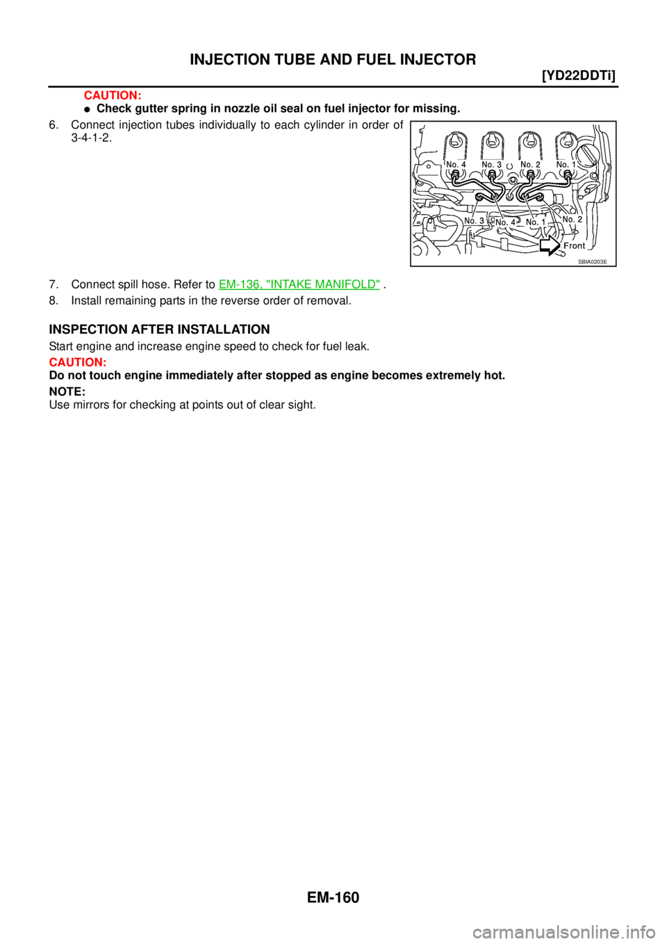
�Check gutter spring in nozzle oil seal on fuel injector for missing.
6. Connect injection tubes individually to each cylinder in order of
3-4-1-2.
7. Connect spill hose. Refer to EM-136, "
INTAKE MANIFOLD" .
8. Install remaining parts in the reverse order of removal.
INSPECTION AFTER INSTALLATION
Start engine and increase engine speed to check for fuel leak.
CAUTION:
Do not touch engine immediately after stopped as engine becomes extremely hot.
NOTE:
Use mirrors for checking at points out of clear sight.
SBIA0203E
Page 221 of 4179
ROCKER COVER
EM-169
[YD22DDTi]
C
D
E
F
G
H
I
J
K
L
MA
EM
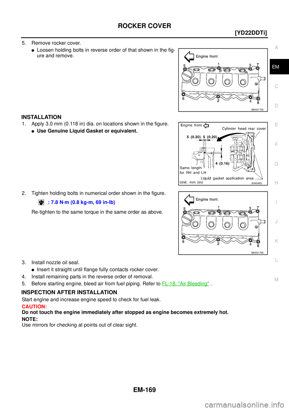
5. Remove rocker cover.
�Loosen holding bolts in reverse order of that shown in the fig-
ure and remove.
INSTALLATION
1. Apply 3.0 mm (0.118 in) dia. on locations shown in the figure.
�Use Genuine Liquid Gasket or equivalent.
2. Tighten holding bolts in numerical order shown in the figure.
Re-tighten to the same torque in the same order as above.
3. Install nozzle oil seal.
�Insert it straight until flange fully contacts rocker cover.
4. Install remaining parts in the reverse order of removal.
5. Before starting engine, bleed air from fuel piping. Refer to FL-18, "
Air Bleeding" .
INSPECTION AFTER INSTALLATION
Start engine and increase engine speed to check for fuel leak.
CAUTION:
Do not touch the engine immediately after stopped as engine becomes extremely hot.
NOTE:
Use mirrors for checking at points out of clear sight.
SBIA0175E
JEM248G
: 7.8 N·m (0.8 kg-m, 69 in-lb)
SBIA0175E
Page 227 of 4179
![NISSAN X-TRAIL 2003 Service Repair Manual CAMSHAFT
EM-175
[YD22DDTi]
C
D
E
F
G
H
I
J
K
L
MA
EM
�Install so that knock pins are positioned in the directions
shown in the figure.
3. Install camshaft brackets.
�Completely remove any foreign ma](/manual-img/5/57404/w960_57404-226.png "NISSAN X-TRAIL 2003 Service Repair Manual CAMSHAFT
EM-175
[YD22DDTi]
C
D
E
F
G
H
I
J
K
L
MA
EM
�Install so that knock pins are positioned in the directions
shown in the figure.
3. Install camshaft brackets.
�Completely remove any foreign ma")
CAMSHAFT
EM-175
[YD22DDTi]
C
D
E
F
G
H
I
J
K
L
MA
EM
�Install so that knock pins are positioned in the directions
shown in the figure.
3. Install camshaft brackets.
�Completely remove any foreign material on back surfaces of camshaft brackets and top surface of cyl-
inder head.
�Install correctly, identifying brackets by the journal No. and
front mark on top surface.
4. Tighten bolts in the order shown in the figure according to the
following procedure:
a. Tighten all bolts.
�Make sure camshaft thrusting parts (on rear side) securely fit
in their mating parts on the cylinder head.
b. Tighten all bolts.
c. Tighten all bolts.
5. Install camshaft sprockets.
�Camshaft sprockets are commonly used for right side and left side.
�Align camshaft sprocket and knock pin on camshaft, and install.
�Holding the hexagonal part of camshaft with a wrench, tighten bolt securing camshaft sprocket.
6. Before installing spill tube after installing secondary timing chain, check and adjust valve clearance. Refer
to EM-175, "
Valve Clearance" .
7. Hereafter, install in the reverse order of removal.
Va l v e C l e a r a n c eEBS00LRS
INSPECTION
�When the camshaft or parts in connection with valves are removed or replaced, and a malfunction has
occurred (poor starting, idling, or other malfunction) due to the misadjustment of the valve clearance,
inspect as follows.
�Inspect and adjust when the engine is cool (at normal temperature).
PBIC2026E
JEM175G
: 2 N·m (0.2 kg-m, 1 ft-lb)
: 6 N·m (0.6 kg-m, 4 ft-lb)
: 12 - 13 N·m (1.2 - 1.4 kg-m, 9 - 10 ft-lb)
JEM160G
Page 230 of 4179
![NISSAN X-TRAIL 2003 Service Repair Manual EM-178
[YD22DDTi]
CAMSHAFT
4. With valve spring in a compressed state, remove the camshaft
pliers (special service tool) by securely setting the outer circum-
ference of the valve lifter with the en](/manual-img/5/57404/w960_57404-229.png "NISSAN X-TRAIL 2003 Service Repair Manual EM-178
[YD22DDTi]
CAMSHAFT
4. With valve spring in a compressed state, remove the camshaft
pliers (special service tool) by securely setting the outer circum-
ference of the valve lifter with the en")
EM-178
[YD22DDTi]
CAMSHAFT
4. With valve spring in a compressed state, remove the camshaft
pliers (special service tool) by securely setting the outer circum-
ference of the valve lifter with the end of the lifter stopper (spe-
cial service tool).
�Hold the lifter stopper by hand until the shim is removed.
CAUTION:
Do not retrieve the camshaft pliers forcefully, as cam-
shaft will be damaged.
5. Move the round hole of adjusting shim to the front with the very
thin screwdriver or like that.
�When adjusting shim on valve lifter will not rotate smoothly,
restart from step 3 to release the end of the lifter stopper (spe-
cial service tool) from touching adjusting shim.
6. Remove adjusting shim from valve lifter by blowing air through
the round hole of the adjusting shim with the air gun.
CAUTION:
To prevent any remaining engine oil from being blown
around, thoroughly wipe the area clean and wear protective
goggles.
7. Remove adjusting shim by using the magnet hand.
8. Measure the thickness of adjusting shim using the micrometer.
�Measure near the center of the shim (the part that touches
camshaft).
9. Select the new adjusting shim from the following methods.
PBIC2322E
PBIC2323E
PBIC2324E
FEM032
Calculation method of the adjusting shim thickness:
R = Thickness of removed shim
N = Thickness of new shim
M = Measured valve clearance
Intake
N = R + [M - 0.28 mm (0.0010 in)]
Exhaust
N = R + [M - 0.30 mm (0.0118 in)]
Page 243 of 4179
PRIMARY TIMING CHAIN
EM-191
[YD22DDTi]
C
D
E
F
G
H
I
J
K
L
MA
EM
a. Apply a continuous bead of liquid gasket with the tube presser
(special service tool: WS39930000) on locations shown in the
figure.
Use Genuine Liquid Gasket or equivalent.
A: Apply bead so that it does not protrude into the oil passage.
B, C: Minimize overlapping area of bead, by starting and ending
at areas of bead as shown in the figure. Apply so that the portion
marked * comes at an external location but cannot be viewed
externally after engine assembly.
D: Leave the start and end areas of the bead slightly protruding
from the case surface.
b. Install four O-rings to the grooves of the cylinder block and fuel
pump bracket.
c. Install rear chain case.
�When installing, align the dowel pin with the pin hole.
PBIC1255E
JEM141G
Page 246 of 4179
![NISSAN X-TRAIL 2003 Service Repair Manual EM-194
[YD22DDTi]
PRIMARY TIMING CHAIN
a. Apply a continuous bead of liquid gasket with the tube presser
(special service tool: WS39930000) as shown in the figure.
A: Leave the start and end areas o](/manual-img/5/57404/w960_57404-245.png "NISSAN X-TRAIL 2003 Service Repair Manual EM-194
[YD22DDTi]
PRIMARY TIMING CHAIN
a. Apply a continuous bead of liquid gasket with the tube presser
(special service tool: WS39930000) as shown in the figure.
A: Leave the start and end areas o")
EM-194
[YD22DDTi]
PRIMARY TIMING CHAIN
a. Apply a continuous bead of liquid gasket with the tube presser
(special service tool: WS39930000) as shown in the figure.
A: Leave the start and end areas of the bead slightly protruding
from the surface.
B: Apply liquid gasket along upper end surface of oil pump hous-
ing.
b. Install oil pump drive spacer to crankshaft.
�Install with the front mark (punched mark) facing the front of
the engine.
c. Install O-ring into the groove of rear chain case.
d. Install oil pump housing.
�When installing, align the inner rotor in the direction of the two facing flats of oil pump drive spacer.
�When installing, align the dowel pin with the pin hole.
e. Tighten fixing bolts in numerical order shown in the figure.
f. After tightening all the bolts, re-tighten in the same order.
14. Check gaps on upper oil pan mounting surface.
�Using straightedge and feeler gauge, measure gaps between
the locations of the following parts:
�If the measured value is out of the standard, install again.
15. Install crankshaft pulley.
a. Install crankshaft pulley to crankshaft.
JEM144G
JEM145G
JEM133G
Oil pump housing and rear chain case:
Standard : – 0.09 to 0.09 mm (– 0.0035 to 0.0035 in)
Rear chain case and cylinder block:
Standard : – 0.19 to 0.07 mm (– 0.0075 to 0.0028 in)
JEM146G
![NISSAN X-TRAIL 2003 Service Repair Manual PRIMARY TIMING CHAIN
EM-191
[YD22DDTi]
C
D
E
F
G
H
I
J
K
L
MA
EM
a. Apply a continuous bead of liquid gasket with the tube presser
(special service tool: WS39930000) on locations shown in the
figure](/manual-img/5/57404/w960_57404-242.png "NISSAN X-TRAIL 2003 Service Repair Manual PRIMARY TIMING CHAIN
EM-191
[YD22DDTi]
C
D
E
F
G
H
I
J
K
L
MA
EM
a. Apply a continuous bead of liquid gasket with the tube presser
(special service tool: WS39930000) on locations shown in the
figure")