Page 1924 of 4179
CL-10
OPERATING CYLINDER
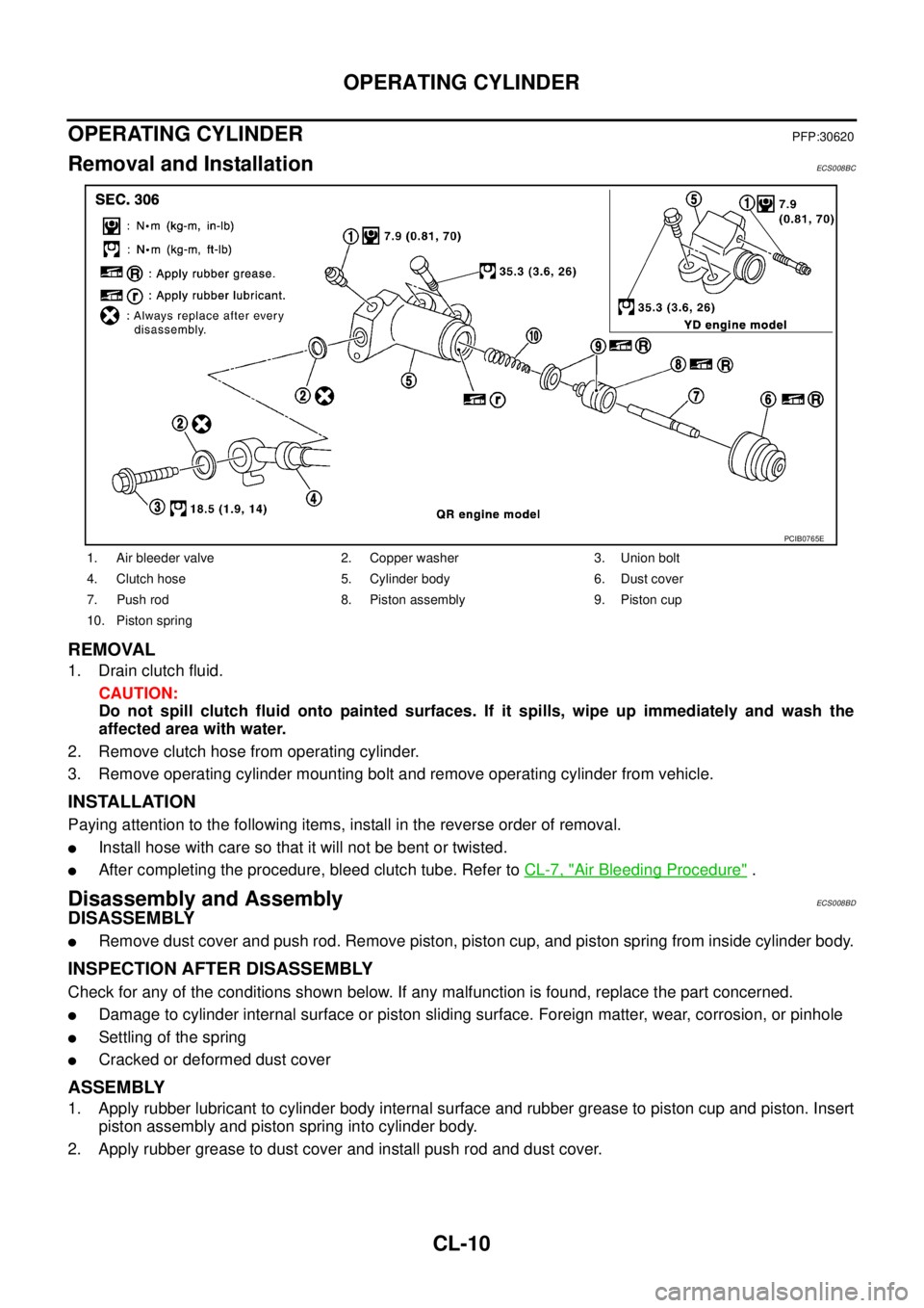
OPERATING CYLINDERPFP:30620
Removal and InstallationECS008BC
REMOVAL
1. Drain clutch fluid.
CAUTION:
Do not spill clutch fluid onto painted surfaces. If it spills, wipe up immediately and wash the
affected area with water.
2. Remove clutch hose from operating cylinder.
3. Remove operating cylinder mounting bolt and remove operating cylinder from vehicle.
INSTALLATION
Paying attention to the following items, install in the reverse order of removal.
�Install hose with care so that it will not be bent or twisted.
�After completing the procedure, bleed clutch tube. Refer to CL-7, "Air Bleeding Procedure" .
Disassembly and AssemblyECS008BD
DISASSEMBLY
�Remove dust cover and push rod. Remove piston, piston cup, and piston spring from inside cylinder body.
INSPECTION AFTER DISASSEMBLY
Check for any of the conditions shown below. If any malfunction is found, replace the part concerned.
�Damage to cylinder internal surface or piston sliding surface. Foreign matter, wear, corrosion, or pinhole
�Settling of the spring
�Cracked or deformed dust cover
ASSEMBLY
1. Apply rubber lubricant to cylinder body internal surface and rubber grease to piston cup and piston. Insert
piston assembly and piston spring into cylinder body.
2. Apply rubber grease to dust cover and install push rod and dust cover.
1. Air bleeder valve 2. Copper washer 3. Union bolt
4. Clutch hose 5. Cylinder body 6. Dust cover
7. Push rod 8. Piston assembly 9. Piston cup
10. Piston spring
PCIB0765E
Page 1935 of 4179
PRECAUTIONS
MT-3
D
E
F
G
H
I
J
K
L
MA
B
MT
PRECAUTIONSPFP:00001
CautionECS008BM
�Do not reuse transaxle oil, once it has been drained.
�Check oil level or replace oil with vehicle on level ground.
�During removal or installation, keep inside of transaxle clear of dust or dirt.
�Check for the correct installation status prior to removal or disassembly. If mating marks are required, be
certain they do not interfere with the function of the parts they are applied to.
�In principle, tighten bolts or nuts gradually in several steps working diagonally from inside to outside. If
tightening sequence is specified, observe it.
�Be careful not to damage sliding surfaces and mating surfaces.
Page 1960 of 4179
MT-28
TRANSAXLE ASSEMBLY
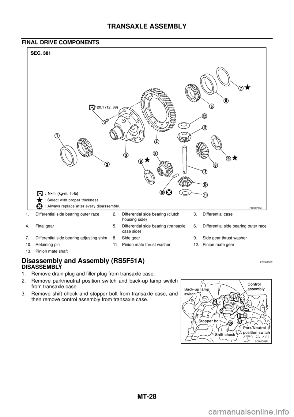
FINAL DRIVE COMPONENTS
Disassembly and Assembly (RS5F51A)ECS008C0
DISASSEMBLY
1. Remove drain plug and filler plug from transaxle case.
2. Remove park/neutral position switch and back-up lamp switch
from transaxle case.
3. Remove shift check and stopper bolt from transaxle case, and
then remove control assembly from transaxle case.
1. Differential side bearing outer race 2. Differential side bearing (clutch
housing side)3. Differential case
4. Final gear 5. Differential side bearing (transaxle
case side)6. Differential side bearing outer race
7. Differential side bearing adjusting shim 8. Side gear 9. Side gear thrust washer
10. Retaining pin 11. Pinion mate thrust washer 12. Pinion mate gear
13. Pinion mate shaft
PCIB0785E
SCIA0389E
Page 1969 of 4179
TRANSAXLE ASSEMBLY
MT-37
D
E
F
G
H
I
J
K
L
MA
B
MT
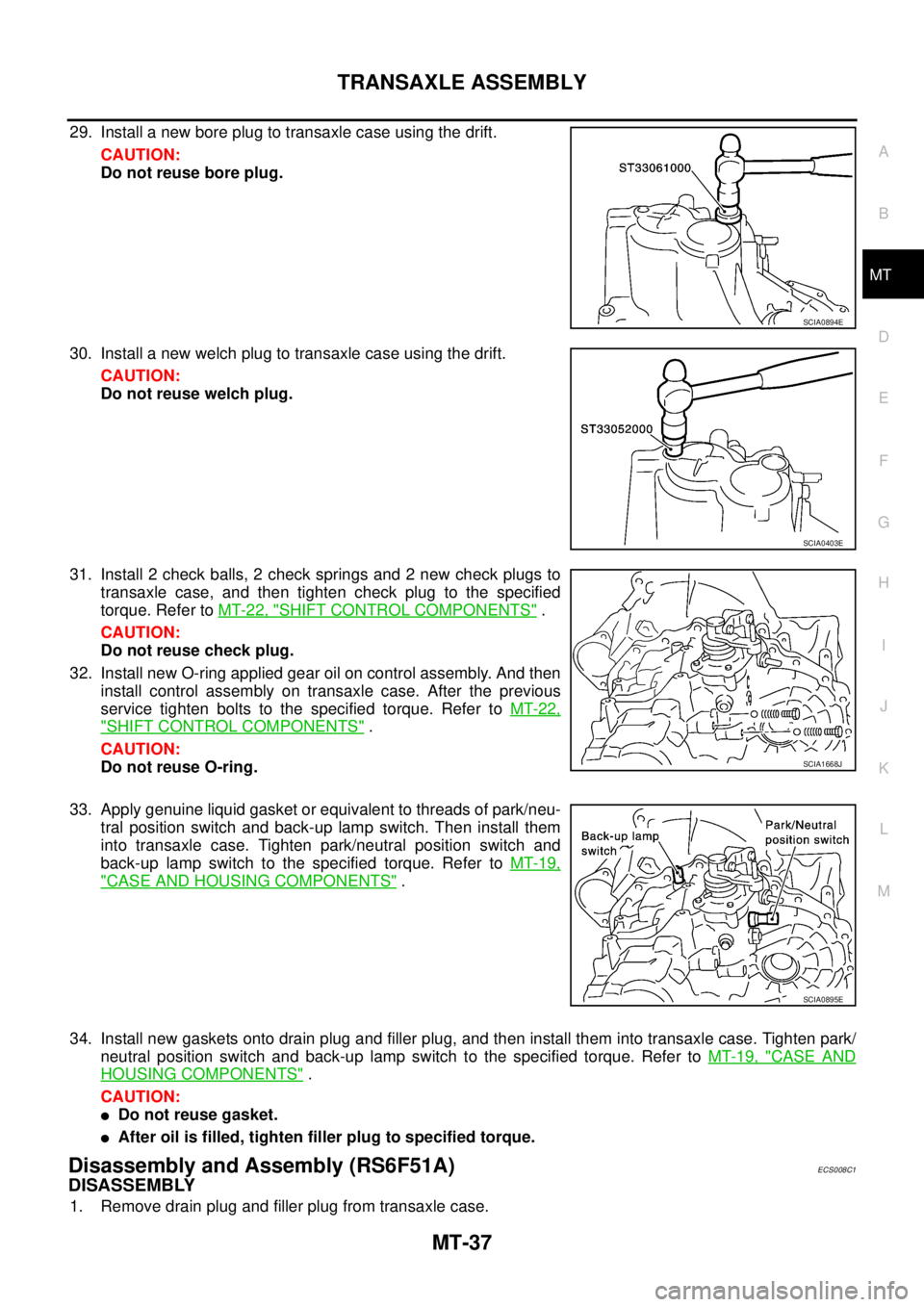
29. Install a new bore plug to transaxle case using the drift.
CAUTION:
Do not reuse bore plug.
30. Install a new welch plug to transaxle case using the drift.
CAUTION:
Do not reuse welch plug.
31. Install 2 check balls, 2 check springs and 2 new check plugs to
transaxle case, and then tighten check plug to the specified
torque. Refer to MT-22, "
SHIFT CONTROL COMPONENTS" .
CAUTION:
Do not reuse check plug.
32. Install new O-ring applied gear oil on control assembly. And then
install control assembly on transaxle case. After the previous
service tighten bolts to the specified torque. Refer to MT-22,
"SHIFT CONTROL COMPONENTS" .
CAUTION:
Do not reuse O-ring.
33. Apply genuine liquid gasket or equivalent to threads of park/neu-
tral position switch and back-up lamp switch. Then install them
into transaxle case. Tighten park/neutral position switch and
back-up lamp switch to the specified torque. Refer to MT-19,
"CASE AND HOUSING COMPONENTS" .
34. Install new gaskets onto drain plug and filler plug, and then install them into transaxle case. Tighten park/
neutral position switch and back-up lamp switch to the specified torque. Refer to MT-19, "
CASE AND
HOUSING COMPONENTS" .
CAUTION:
�Do not reuse gasket.
�After oil is filled, tighten filler plug to specified torque.
Disassembly and Assembly (RS6F51A)ECS008C1
DISASSEMBLY
1. Remove drain plug and filler plug from transaxle case.
SCIA0894E
SCIA0403E
SCIA1668J
SCIA0895E
Page 1979 of 4179
TRANSAXLE ASSEMBLY
MT-47
D
E
F
G
H
I
J
K
L
MA
B
MT
36. Install new O-ring applied gear oil on control assembly. And then
install control assembly on transaxle case. After the precious
service tighten bolts to the specified torque. Refer to MT-27,
"SHIFT CONTROL COMPONENTS" .
CAUTION:
Do not reuse O-ring.
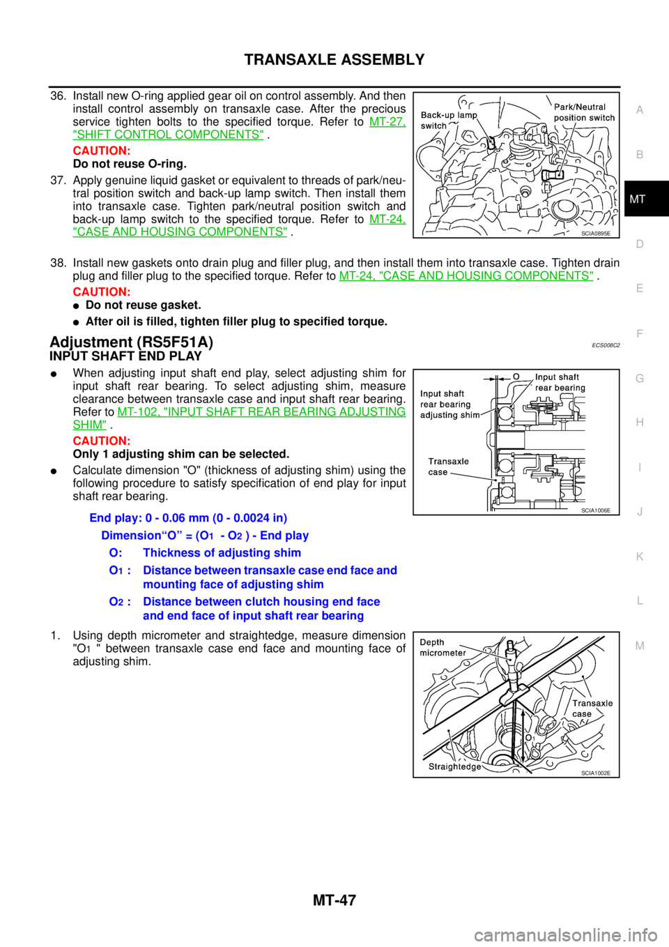
37. Apply genuine liquid gasket or equivalent to threads of park/neu-
tral position switch and back-up lamp switch. Then install them
into transaxle case. Tighten park/neutral position switch and
back-up lamp switch to the specified torque. Refer to MT-24,
"CASE AND HOUSING COMPONENTS" .
38. Install new gaskets onto drain plug and filler plug, and then install them into transaxle case. Tighten drain
plug and filler plug to the specified torque. Refer to MT-24, "
CASE AND HOUSING COMPONENTS" .
CAUTION:
�Do not reuse gasket.
�After oil is filled, tighten filler plug to specified torque.
Adjustment (RS5F51A)ECS008C2
INPUT SHAFT END PLAY
�When adjusting input shaft end play, select adjusting shim for
input shaft rear bearing. To select adjusting shim, measure
clearance between transaxle case and input shaft rear bearing.
Refer to MT-102, "
INPUT SHAFT REAR BEARING ADJUSTING
SHIM" .
CAUTION:
Only 1 adjusting shim can be selected.
�Calculate dimension "O" (thickness of adjusting shim) using the
following procedure to satisfy specification of end play for input
shaft rear bearing.
1. Using depth micrometer and straightedge, measure dimension
"O
1 " between transaxle case end face and mounting face of
adjusting shim.
SCIA0895E
End play: 0 - 0.06 mm (0 - 0.0024 in)
Dimension“O” = (O
1 - O2 ) - End play
O: Thickness of adjusting shim
O
1 : Distance between transaxle case end face and
mounting face of adjusting shim
O
2 : Distance between clutch housing end face
and end face of input shaft rear bearing
SCIA1006E
SCIA1002E
Page 2440 of 4179
AT-404
[ALL]
ON-VEHICLE SERVICE
ON-VEHICLE SERVICEPFP:00000
Control Valve Assembly and AccumulatorsECS0040C
COMPONENTS
1. Transaxle 2. Lip seal 3. O-ring
4. Servo release accumulator piston 5. O-ring 6. Return spring
7. Control valve assembly 8. Oil pan gasket 9. Drain plug gasket
10. Drain plug 11. Magnet 12. Oil pan
13. Oil pan fitting bolt 14. Snap ring 15. O-ring
16. O-ring 17. N-D accumulator piston 18. O-ring
19. Return spring
SCIA4320E
Page 2457 of 4179
![NISSAN X-TRAIL 2003 Service Repair Manual OVERHAUL
AT-421
[ALL]
D
E
F
G
H
I
J
K
L
MA
B
AT
10. Bracket 11. Anchor end pin 12. Lock nut
13. Transaxle case 14. Brake band 15. Bearing retainer
16. Seal ring 17. Radial needle bearing 18. Snap ri](/manual-img/5/57404/w960_57404-2456.png "NISSAN X-TRAIL 2003 Service Repair Manual OVERHAUL
AT-421
[ALL]
D
E
F
G
H
I
J
K
L
MA
B
AT
10. Bracket 11. Anchor end pin 12. Lock nut
13. Transaxle case 14. Brake band 15. Bearing retainer
16. Seal ring 17. Radial needle bearing 18. Snap ri")
OVERHAUL
AT-421
[ALL]
D
E
F
G
H
I
J
K
L
MA
B
AT
10. Bracket 11. Anchor end pin 12. Lock nut
13. Transaxle case 14. Brake band 15. Bearing retainer
16. Seal ring 17. Radial needle bearing 18. Snap ring
19. Reduction pinion gear 20. Reduction pinion gear bearing inner
race21. Reduction pinion gear bearing outer
race
22. Strut 23. O-ring 24. O-ring
25. Servo release accumulator piston 26. O-ring 27. Return spring
28. Control valve assembly 29. Oil pan gasket 30. Drain plug gasket
31. Drain plug 32. Magnet 33. Oil pan
34. Oil pan fitting bolt 35. Low & reverse brake tube 36. Oil sleeve
37. O-ring 38. Snap ring 39. O-ring
40. N-D accumulator piston 41. Return spring 42. Lip seal
43. Parking rod 44. Retaining pin 45. Manual shaft oil seal
46. Detent spring 47. Manual shaft 48. Retaining pin
49. Manual plate 50. Parking rod plate 51. O/D servo piston
52. O/D servo piston retainer 53. O/D servo piston retainer fitting bolt 54. O-ring
55. D-ring 56. Servo piston retainer 57. O-ring
58. E-ring 59. Spring retainer 60. O/D servo return spring
61. D-ring 62. Band servo piston 63. Band servo thrust washer
64. Band servo piston stem 65. 2nd servo return spring 66. Parking pawl
67. Parking shaft 68. Return spring 69. Paring pawl spacer
70. PNP switch 71. Idler gear bearing 72. Idler gear
73. Idler gear lock nut 74. Reduction pinion gear adjusting
shim75. Output shaft adjusting shim
76. Side cover
Page 2647 of 4179
TRANSFER ASSEMBLY
TF-71
C
E
F
G
H
I
J
K
L
MA
B
TF
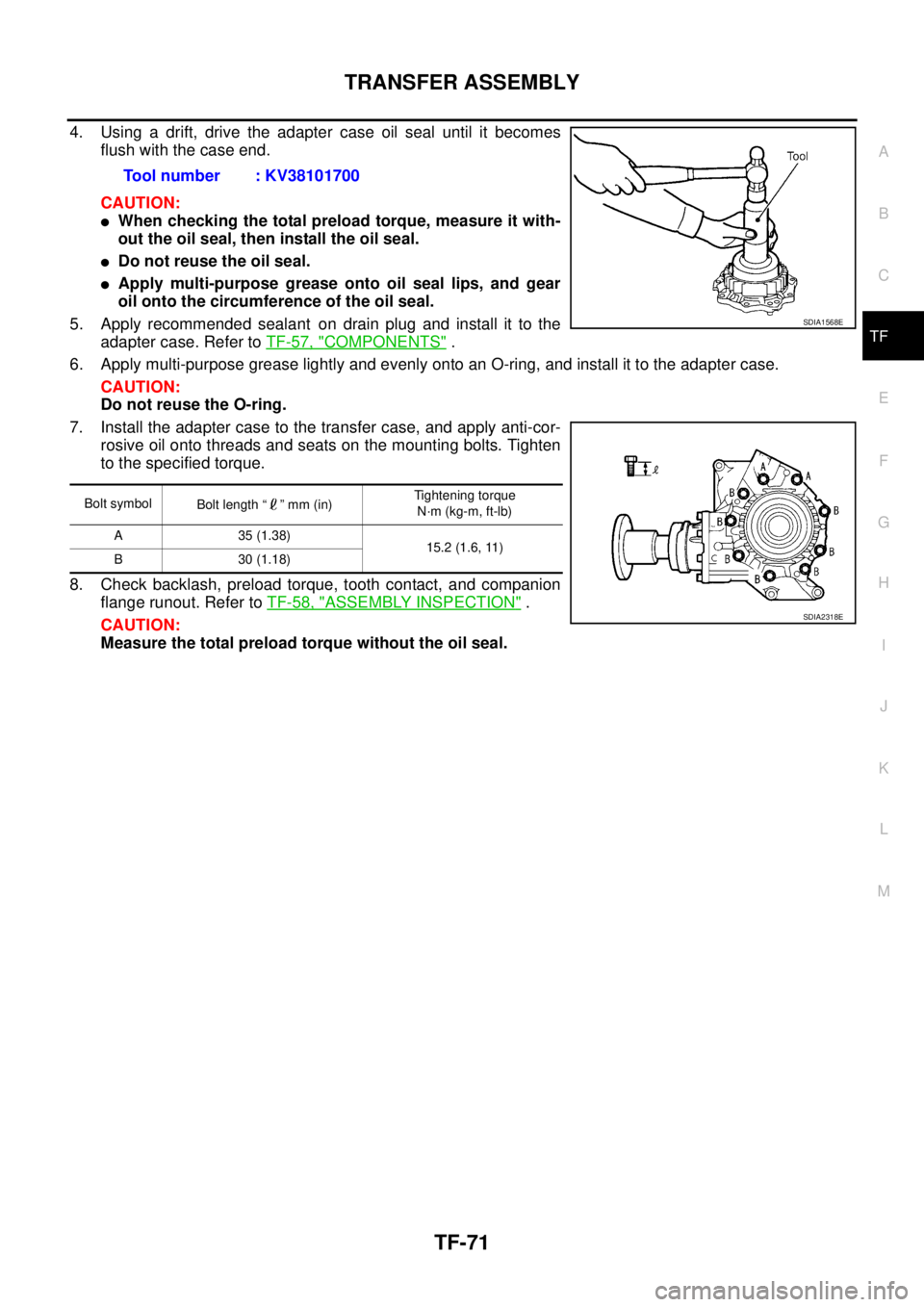
4. Using a drift, drive the adapter case oil seal until it becomes
flush with the case end.
CAUTION:
�When checking the total preload torque, measure it with-
out the oil seal, then install the oil seal.
�Do not reuse the oil seal.
�Apply multi-purpose grease onto oil seal lips, and gear
oil onto the circumference of the oil seal.
5. Apply recommended sealant on drain plug and install it to the
adapter case. Refer to TF-57, "
COMPONENTS" .
6. Apply multi-purpose grease lightly and evenly onto an O-ring, and install it to the adapter case.
CAUTION:
Do not reuse the O-ring.
7. Install the adapter case to the transfer case, and apply anti-cor-
rosive oil onto threads and seats on the mounting bolts. Tighten
to the specified torque.
8. Check backlash, preload torque, tooth contact, and companion
flange runout. Refer to TF-58, "
ASSEMBLY INSPECTION" .
CAUTION:
Measure the total preload torque without the oil seal.Tool number : KV38101700
Bolt symbol
Bolt length “ ” mm (in)Tightening torque
N·m (kg-m, ft-lb)
A 35 (1.38)
15.2 (1.6, 11)
B 30 (1.18)
SDIA1568E
SDIA2318E

![NISSAN X-TRAIL 2003 Service Repair Manual AT-404
[ALL]
ON-VEHICLE SERVICE
ON-VEHICLE SERVICEPFP:00000
Control Valve Assembly and AccumulatorsECS0040C
COMPONENTS
1. Transaxle 2. Lip seal 3. O-ring
4. Servo release accumulator piston 5. O-rin](/manual-img/5/57404/w960_57404-2439.png "NISSAN X-TRAIL 2003 Service Repair Manual AT-404
[ALL]
ON-VEHICLE SERVICE
ON-VEHICLE SERVICEPFP:00000
Control Valve Assembly and AccumulatorsECS0040C
COMPONENTS
1. Transaxle 2. Lip seal 3. O-ring
4. Servo release accumulator piston 5. O-rin")