Page 3520 of 4179
ATC-124
INTAKE SENSOR
INTAKE SENSORPFP:27723
Removal and InstallationEJS004GI
REMOVAL
1. Remove evaporator. Refer to ATC-158, "Removal and Installation of Evaporator" .
2. Remove intake sensor.
INSTALLATION
Installation is basically the reverse order of removal.
CAUTION:
�Replace O-rings for A/C piping with new ones. Before installing, apply compressor oil to them.
�Make sure mounting position of intake sensor bracket.
�When recharging refrigerant, check for leaks.
RJIA0051E
Page 3528 of 4179
ATC-132
HEATER & COOLING UNIT ASSEMBLY
9. Remove steering member.
10. Remove heater & cooling unit.
CAUTION:
Cap or wrap the joint of the pipe with suitable material such as vinyl tape to avoid the entry of air.
INSTALLATION
Installation is basically the reverse order of removal.
CAUTION:
�Replace the O-ring of the low-pressure flexible hose and the high-pressure pipe with a new one,
and then apply compressor oil to it when installing it.
�When recharging refrigerant, check for leaks.
NOTE:
When filling radiator with coolant, refer to CO-9, "
Changing Engine Coolant" for QR engine or CO-31, "Chang-
ing Engine Coolant" for YD engine.
Disassembly and AssemblyEJS000UU
NOTE:
This illustration is for RHD models. The layout for LHD models is symmetrically opposite.
RJIA2404E
Page 3537 of 4179
REFRIGERANT LINES
ATC-141
C
D
E
F
G
H
I
K
L
MA
B
AT C
REFRIGERANT LINESPFP:92600
HFC-134a (R-134a) Service ProcedureEJS000V7
SETTING OF SERVICE TOOLS AND EQUIPMENT
Discharging Refrigerant
WARNING:
Avoid breathing A/C refrigerant and lubricant vapor or mist. Exposure may irritate eyes, nose and
throat. Use only approved recovery/recycling equipment to discharge HFC-134a (R-134a) refrigerant. If
accidental system discharge occurs, ventilate work area before resuming service. Additional health
and safety information may be obtained from refrigerant and lubricant manufacturers.
Evacuating System and Charging Refrigerant
SHA539DE
SHA540DC
Page 3542 of 4179
ATC-146
REFRIGERANT LINES
6. Remove mounting bolts from compressor.
7. Remove compressor from the lower side of the vehicle.
INSTALLATION
Installation is basically the reverse order of removal.
CAUTION:
�Replace the O-ring of low-pressure flexible hose and high-pressure flexible hose with a new one,
then apply compressor oil to it when installing it.
�When recharging refrigerant, check for leaks.
Removal and Installation of Compressor ClutchEJS000VA
REMOVAL
Overhaul (With Gasoline Engine: CWV-615M Compressor)
1. When removing center bolt, hold clutch disc with wrench.
RJIA0021E
RJIA0580E
RHA136E
Page 3550 of 4179

ATC-154
REFRIGERANT LINES
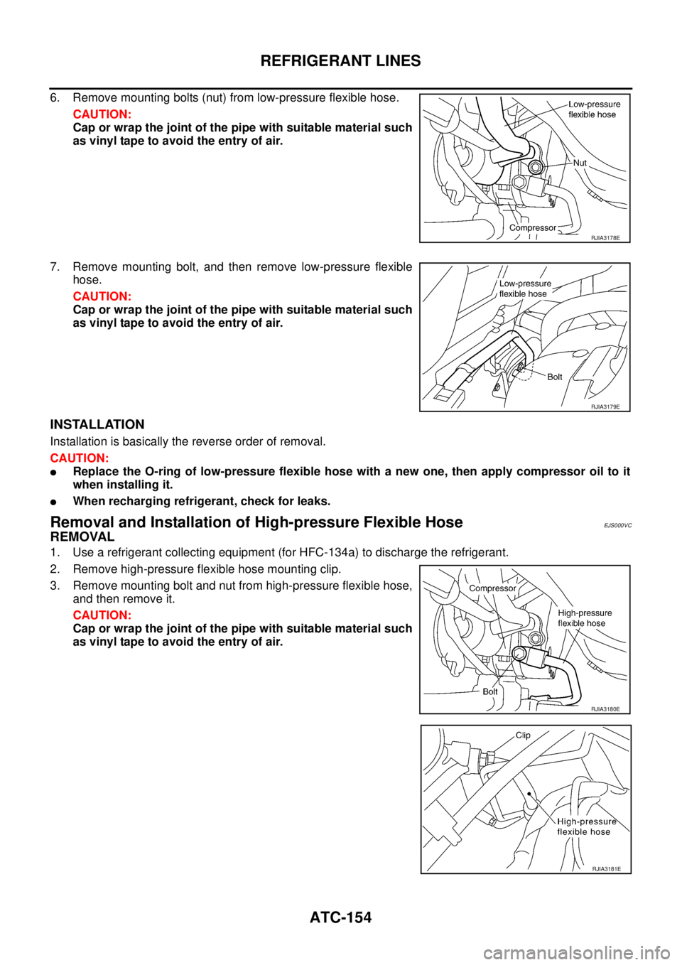
6. Remove mounting bolts (nut) from low-pressure flexible hose.
CAUTION:
Cap or wrap the joint of the pipe with suitable material such
as vinyl tape to avoid the entry of air.
7. Remove mounting bolt, and then remove low-pressure flexible
hose.
CAUTION:
Cap or wrap the joint of the pipe with suitable material such
as vinyl tape to avoid the entry of air.
INSTALLATION
Installation is basically the reverse order of removal.
CAUTION:
�Replace the O-ring of low-pressure flexible hose with a new one, then apply compressor oil to it
when installing it.
�When recharging refrigerant, check for leaks.
Removal and Installation of High-pressure Flexible HoseEJS000VC
REMOVAL
1. Use a refrigerant collecting equipment (for HFC-134a) to discharge the refrigerant.
2. Remove high-pressure flexible hose mounting clip.
3. Remove mounting bolt and nut from high-pressure flexible hose,
and then remove it.
CAUTION:
Cap or wrap the joint of the pipe with suitable material such
as vinyl tape to avoid the entry of air.
RJIA3178E
RJIA3179E
RJIA3180E
RJIA3181E
Page 3551 of 4179

REFRIGERANT LINES
ATC-155
C
D
E
F
G
H
I
K
L
MA
B
AT C
INSTALLATION
Installation is basically the reverse order of removal.
CAUTION:
�Replace the O-ring of high-pressure flexible hose with a new one, then apply compressor oil to it
when installing it.
�When recharging refrigerant, check for leaks.
Removal and Installation of High-pressure PipeEJS000VD
REMOVAL
1. Use a refrigerant collecting equipment (for HFC-134a) to discharge the refrigerant.
2. Remove low-pressure flexible hose. Refer to ATC-153, "
Removal and Installation of Low-pressure Flexi-
ble Hose" .
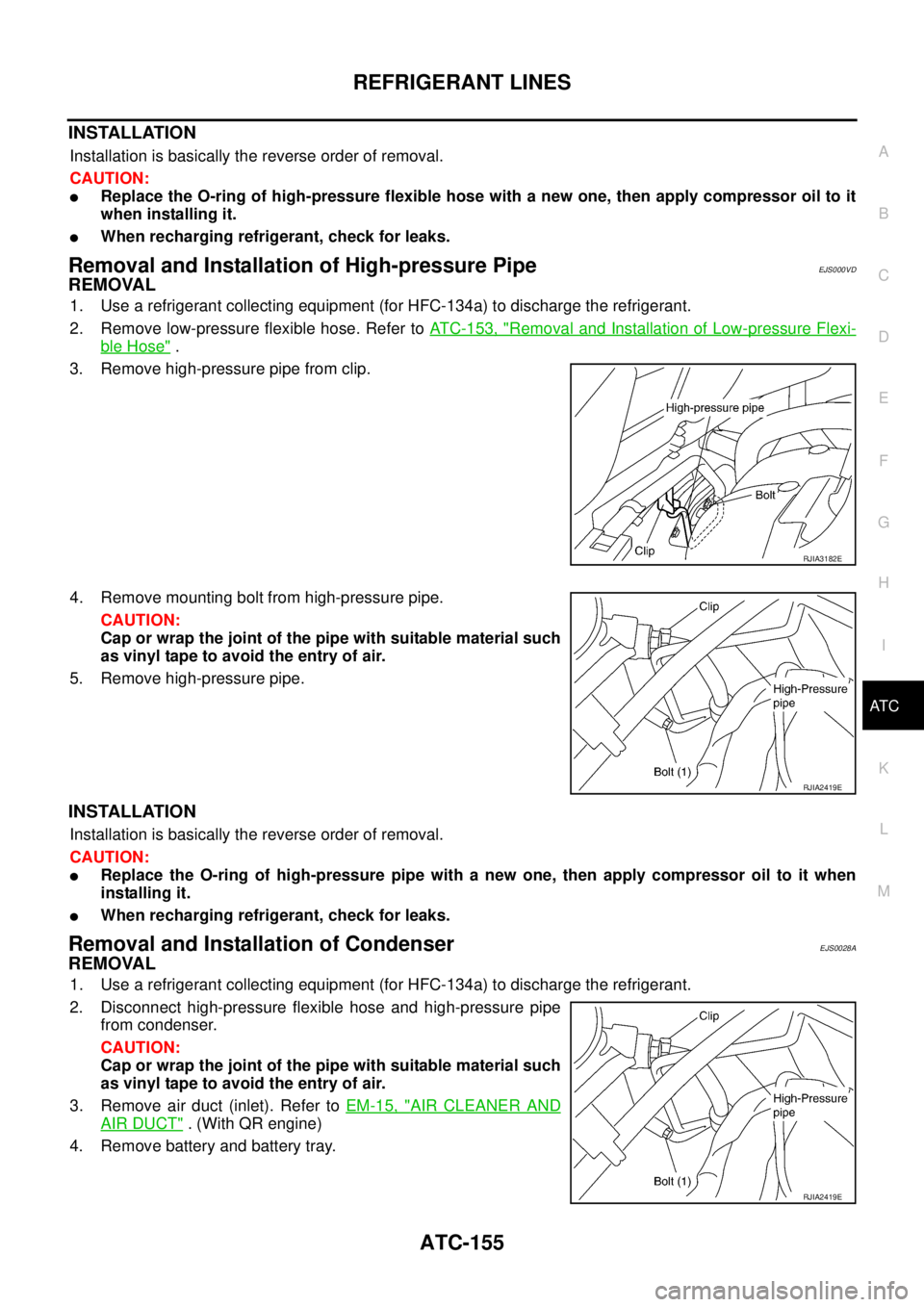
3. Remove high-pressure pipe from clip.
4. Remove mounting bolt from high-pressure pipe.
CAUTION:
Cap or wrap the joint of the pipe with suitable material such
as vinyl tape to avoid the entry of air.
5. Remove high-pressure pipe.
INSTALLATION
Installation is basically the reverse order of removal.
CAUTION:
�Replace the O-ring of high-pressure pipe with a new one, then apply compressor oil to it when
installing it.
�When recharging refrigerant, check for leaks.
Removal and Installation of CondenserEJS0028A
REMOVAL
1. Use a refrigerant collecting equipment (for HFC-134a) to discharge the refrigerant.
2. Disconnect high-pressure flexible hose and high-pressure pipe
from condenser.
CAUTION:
Cap or wrap the joint of the pipe with suitable material such
as vinyl tape to avoid the entry of air.
3. Remove air duct (inlet). Refer to EM-15, "
AIR CLEANER AND
AIR DUCT" . (With QR engine)
4. Remove battery and battery tray.
RJIA3182E
RJIA2419E
RJIA2419E
Page 3552 of 4179

ATC-156
REFRIGERANT LINES
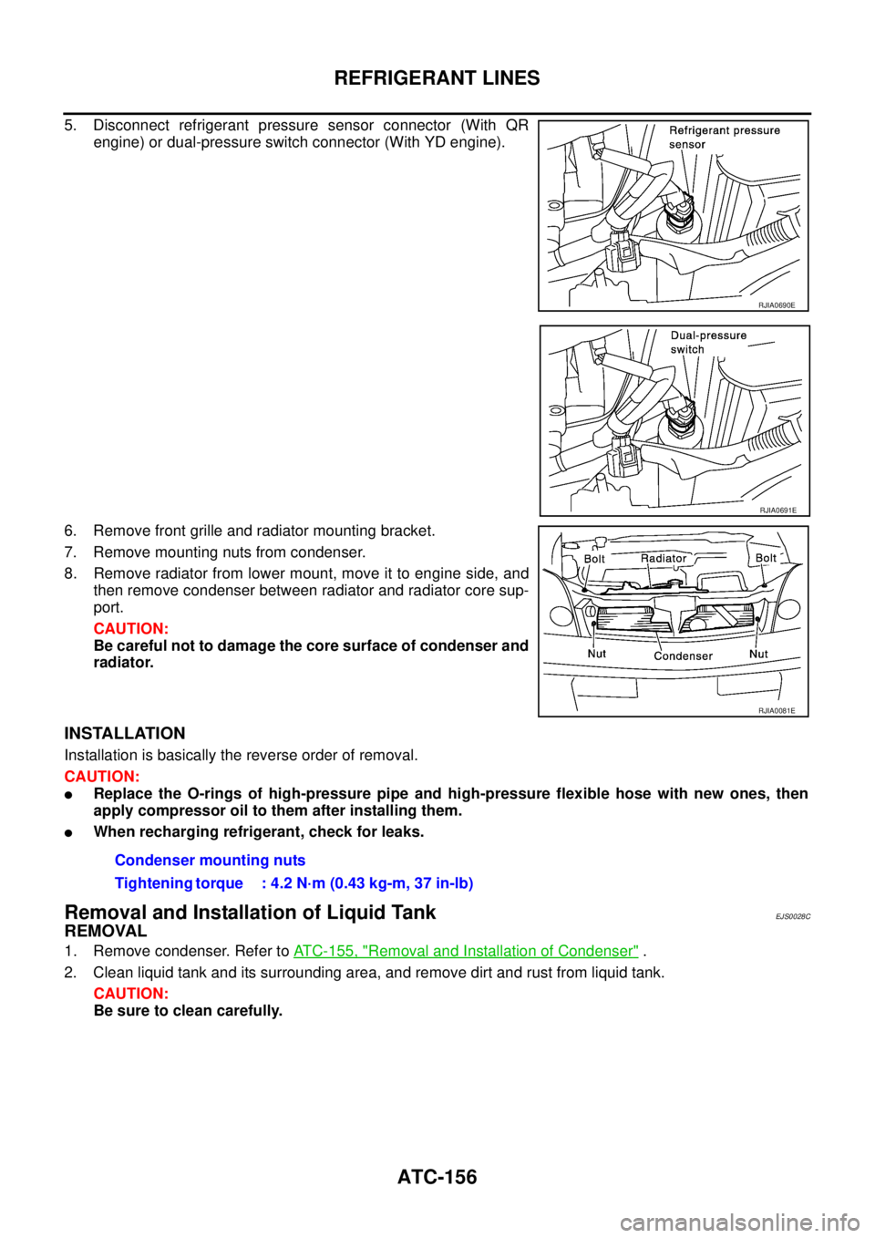
5. Disconnect refrigerant pressure sensor connector (With QR
engine) or dual-pressure switch connector (With YD engine).
6. Remove front grille and radiator mounting bracket.
7. Remove mounting nuts from condenser.
8. Remove radiator from lower mount, move it to engine side, and
then remove condenser between radiator and radiator core sup-
port.
CAUTION:
Be careful not to damage the core surface of condenser and
radiator.
INSTALLATION
Installation is basically the reverse order of removal.
CAUTION:
�Replace the O-rings of high-pressure pipe and high-pressure flexible hose with new ones, then
apply compressor oil to them after installing them.
�When recharging refrigerant, check for leaks.
Removal and Installation of Liquid TankEJS0028C
REMOVAL
1. Remove condenser. Refer to ATC-155, "Removal and Installation of Condenser" .
2. Clean liquid tank and its surrounding area, and remove dirt and rust from liquid tank.
CAUTION:
Be sure to clean carefully.
RJIA0690E
RJIA0691E
RJIA0081E
Condenser mounting nuts
Tightening torque : 4.2 N·m (0.43 kg-m, 37 in-lb)
Page 3553 of 4179

REFRIGERANT LINES
ATC-157
C
D
E
F
G
H
I
K
L
MA
B
AT C
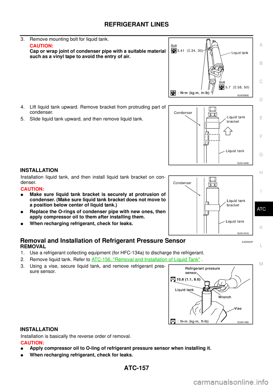
3. Remove mounting bolt for liquid tank.
CAUTION:
Cap or wrap joint of condenser pipe with a suitable material
such as a vinyl tape to avoid the entry of air.
4. Lift liquid tank upward. Remove bracket from protruding part of
condenser.
5. Slide liquid tank upward, and then remove liquid tank.
INSTALLATION
Installation liquid tank, and then install liquid tank bracket on con-
denser.
CAUTION:
�Make sure liquid tank bracket is securely at protrusion of
condenser. (Make sure liquid tank bracket does not move to
a position below center of liquid tank.)
�Replace the O-rings of condenser pipe with new ones, then
apply compressor oil to them after installing them.
�When recharging refrigerant, check for leaks.
Removal and Installation of Refrigerant Pressure SensorEJS004GF
REMOVAL
1. Use a refrigerant collecting equipment (for HFC-134a) to discharge the refrigerant.
2. Remove liquid tank. Refer to ATC-156, "
Removal and Installation of Liquid Tank" .
3. Using a vise, secure liquid tank, and remove refrigerant pres-
sure sensor.
INSTALLATION
Installation is basically the reverse order of removal.
CAUTION:
�Apply compressor oil to O-ling of refrigerant pressure sensor when installing it.
�When recharging refrigerant, check for leaks.
RJIA2895E
RJIA1440E
RJIA1441E
RJIA2148E