Page 2265 of 4179
TROUBLE DIAGNOSES FOR SYMPTOMS
AT-229
[EURO-OBD]
D
E
F
G
H
I
J
K
L
MA
B
AT
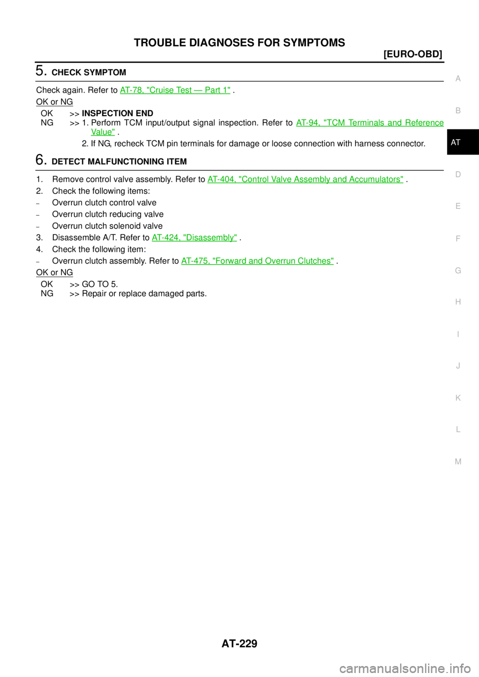
5. CHECK SYMPTOM
Check again. Refer to AT- 7 8 , "
Cruise Test — Part 1" .
OK or NG
OK >>INSPECTION END
NG >> 1. Perform TCM input/output signal inspection. Refer to AT- 9 4 , "
TCM Terminals and Reference
Va l u e" .
2. If NG, recheck TCM pin terminals for damage or loose connection with harness connector.
6. DETECT MALFUNCTIONING ITEM
1. Remove control valve assembly. Refer to AT- 4 0 4 , "
Control Valve Assembly and Accumulators" .
2. Check the following items:
–Overrun clutch control valve
–Overrun clutch reducing valve
–Overrun clutch solenoid valve
3. Disassemble A/T. Refer to AT- 4 2 4 , "
Disassembly" .
4. Check the following item:
–Overrun clutch assembly. Refer to AT- 4 7 5 , "Forward and Overrun Clutches" .
OK or NG
OK >> GO TO 5.
NG >> Repair or replace damaged parts.
Page 2270 of 4179
AT-234
[EURO-OBD]
TROUBLE DIAGNOSES FOR SYMPTOMS
5. DETECT MALFUNCTIONING ITEM
1. Remove control valve assembly. Refer to AT- 4 0 4 , "
Control Valve Assembly and Accumulators" .
2. Check the following items:
–Overrun clutch control valve
–Overrun clutch solenoid valve
–Shift valve A
–Shift solenoid valve A
3. Disassemble A/T. Refer to AT- 4 2 4 , "
Disassembly" .
4. Check the following items:
–Servo piston assembly
–Brake band
OK or NG
OK >> GO TO 6.
NG >> Repair or replace damaged parts.
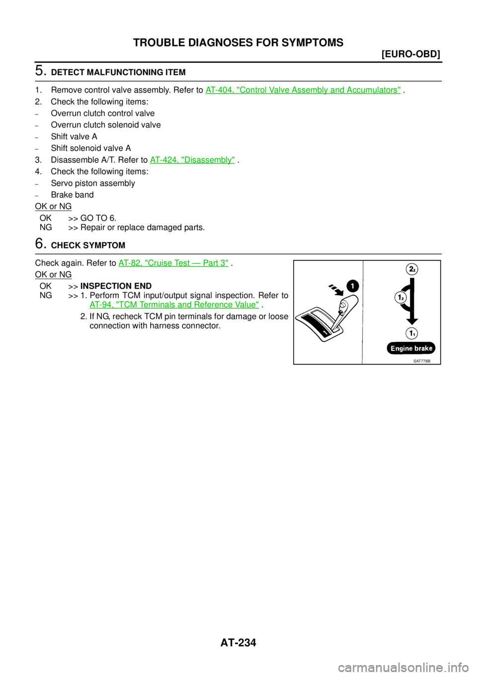
6. CHECK SYMPTOM
Check again. Refer to AT- 8 2 , "
Cruise Test — Part 3" .
OK or NG
OK >>INSPECTION END
NG >> 1. Perform TCM input/output signal inspection. Refer to
AT- 9 4 , "
TCM Terminals and Reference Value" .
2. If NG, recheck TCM pin terminals for damage or loose
connection with harness connector.
SAT778B
Page 2272 of 4179
AT-236
[EURO-OBD]
TROUBLE DIAGNOSES FOR SYMPTOMS
5. DETECT MALFUNCTIONING ITEM
1. Remove control valve assembly. Refer to AT- 4 0 4 , "
Control Valve Assembly and Accumulators" .
2. Check the following items:
–Overrun clutch solenoid valve
–Shift valve A
3. Disassemble A/T. Refer to AT- 4 2 4 , "
Disassembly" .
4. Check the following items:
–Overrun clutch assembly. Refer to AT- 4 7 5 , "Forward and Overrun Clutches" .
–Low & reverse bake assembly
OK or NG
OK >> GO TO 6.
NG >> Repair or replace damaged parts.
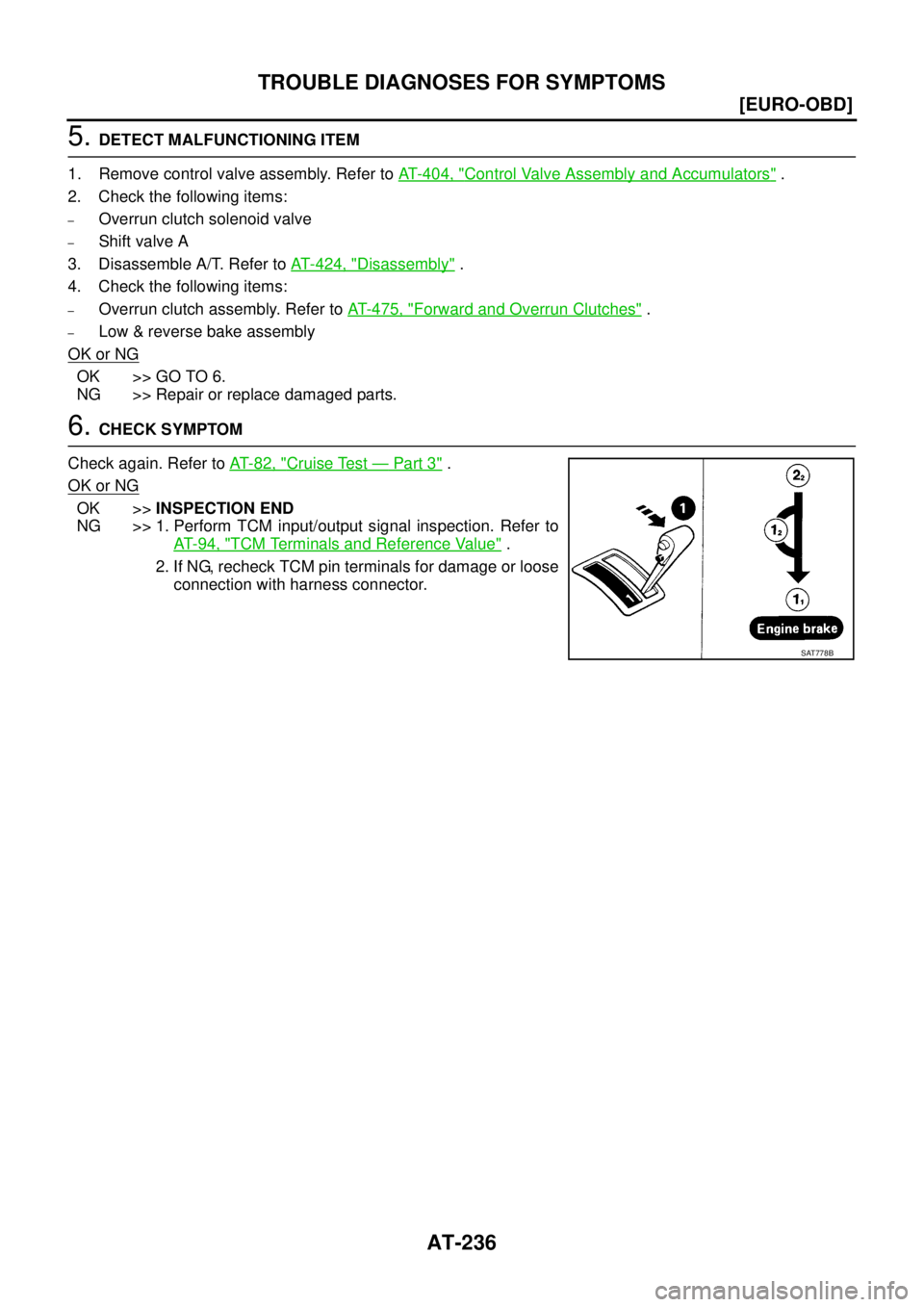
6. CHECK SYMPTOM
Check again. Refer to AT- 8 2 , "
Cruise Test — Part 3" .
OK or NG
OK >>INSPECTION END
NG >> 1. Perform TCM input/output signal inspection. Refer to
AT- 9 4 , "
TCM Terminals and Reference Value" .
2. If NG, recheck TCM pin terminals for damage or loose
connection with harness connector.
SAT778B
Page 2280 of 4179
AT-244
[EXC.F/EURO-OBD]
ON BOARD DIAGNOSTIC SYSTEM DESCRIPTION
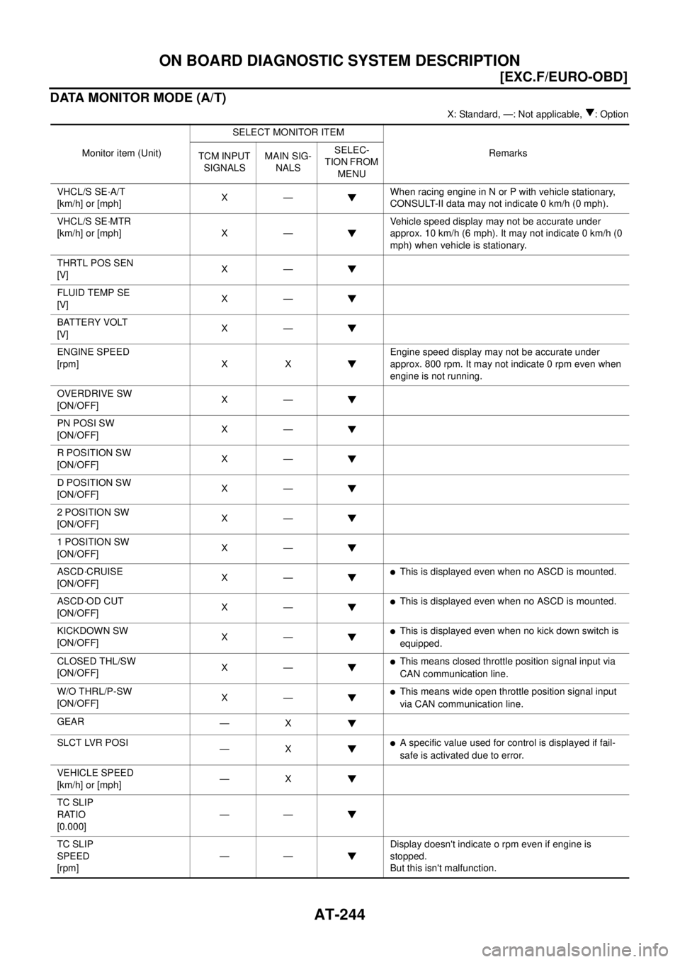
DATA MONITOR MODE (A/T)
X: Standard, —: Not applicable, : Option
Monitor item (Unit)SELECT MONITOR ITEM
Remarks
TCM INPUT
SIGNALSMAIN SIG-
NALSSELEC-
TION FROM
MENU
VHCL/S SE·A/T
[km/h] or [mph]X—When racing engine in N or P with vehicle stationary,
CONSULT-II data may not indicate 0 km/h (0 mph).
VHCL/S SE·MTR
[km/h] or [mph] X —Vehicle speed display may not be accurate under
approx. 10 km/h (6 mph). It may not indicate 0 km/h (0
mph) when vehicle is stationary.
THRTL POS SEN
[V]X—
FLUID TEMP SE
[V]X—
BATTERY VOLT
[V]X—
ENGINE SPEED
[rpm] X XEngine speed display may not be accurate under
approx. 800 rpm. It may not indicate 0 rpm even when
engine is not running.
OVERDRIVE SW
[ON/OFF]X—
PN POSI SW
[ON/OFF]X—
R POSITION SW
[ON/OFF]X—
D POSITION SW
[ON/OFF]X—
2 POSITION SW
[ON/OFF]X—
1 POSITION SW
[ON/OFF]X—
ASCD·CRUISE
[ON/OFF]X—
�This is displayed even when no ASCD is mounted.
ASCD·OD CUT
[ON/OFF]X—
�This is displayed even when no ASCD is mounted.
KICKDOWN SW
[ON/OFF]X—
�This is displayed even when no kick down switch is
equipped.
CLOSED THL/SW
[ON/OFF]X—
�This means closed throttle position signal input via
CAN communication line.
W/O THRL/P-SW
[ON/OFF]X—
�This means wide open throttle position signal input
via CAN communication line.
GEAR
—X
SLCT LVR POSI
—X
�A specific value used for control is displayed if fail-
safe is activated due to error.
VEHICLE SPEED
[km/h] or [mph]—X
TC SLIP
RATIO
[0.000]——
TC SLIP
SPEED
[rpm]——Display doesn't indicate o rpm even if engine is
stopped.
But this isn't malfunction.
Page 2290 of 4179
AT-254
[EXC.F/EURO-OBD]
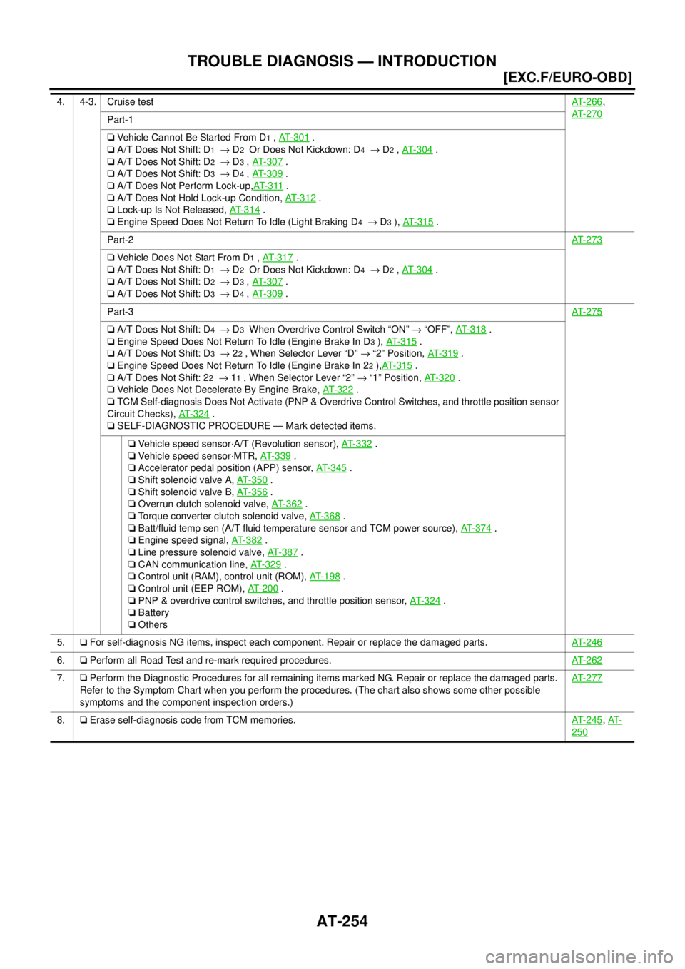
TROUBLE DIAGNOSIS — INTRODUCTION
4. 4-3. Cruise testAT-266,
AT-270
Part-1
❏ Vehicle Cannot Be Started From D
1 , AT- 3 0 1 .
❏ A/T Does Not Shift: D
1 → D2 Or Does Not Kickdown: D4 → D2 , AT-304 .
❏ A/T Does Not Shift: D
2 → D3 , AT- 3 0 7 .
❏ A/T Does Not Shift: D
3 → D4 , AT- 3 0 9 .
❏ A/T Does Not Perform Lock-up,AT- 3 11
.
❏ A/T Does Not Hold Lock-up Condition, AT- 3 1 2
.
❏ Lock-up Is Not Released, AT- 3 1 4
.
❏ Engine Speed Does Not Return To Idle (Light Braking D
4 → D3 ), AT-315 .
Part-2AT-273
❏ Vehicle Does Not Start From D1 , AT- 3 1 7 .
❏ A/T Does Not Shift: D
1 → D2 Or Does Not Kickdown: D4 → D2 , AT-304 .
❏ A/T Does Not Shift: D
2 → D3 , AT- 3 0 7 .
❏ A/T Does Not Shift: D
3 → D4 , AT- 3 0 9 .
Part-3AT-275
❏ A/T Does Not Shift: D4 → D3 When Overdrive Control Switch “ON” → “OFF”, AT-318 .
❏ Engine Speed Does Not Return To Idle (Engine Brake In D
3 ), AT- 3 1 5 .
❏ A/T Does Not Shift: D
3 → 22 , When Selector Lever “D” → “2” Position, AT- 3 1 9 .
❏ Engine Speed Does Not Return To Idle (Engine Brake In 2
2 ),AT-315 .
❏ A/T Does Not Shift: 2
2 → 11 , When Selector Lever “2” → “1” Position, AT-320 .
❏ Vehicle Does Not Decelerate By Engine Brake, AT- 3 2 2
.
❏ TCM Self-diagnosis Does Not Activate (PNP & Overdrive Control Switches, and throttle position sensor
Circuit Checks), AT-324
.
❏ SELF-DIAGNOSTIC PROCEDURE — Mark detected items.
❏ Vehicle speed sensor·A/T (Revolution sensor), AT-332
.
❏ Vehicle speed sensor·MTR, AT- 3 3 9
.
❏ Accelerator pedal position (APP) sensor, AT-345
.
❏ Shift solenoid valve A, AT-350
.
❏ Shift solenoid valve B, AT-356
.
❏ Overrun clutch solenoid valve, AT-362
.
❏ Torque converter clutch solenoid valve, AT- 3 6 8
.
❏ Batt/fluid temp sen (A/T fluid temperature sensor and TCM power source), AT-374
.
❏ Engine speed signal, AT-382
.
❏ Line pressure solenoid valve, AT-387
.
❏ CAN communication line, AT-329
.
❏ Control unit (RAM), control unit (ROM), AT- 1 9 8
.
❏ Control unit (EEP ROM), AT- 2 0 0
.
❏ PNP & overdrive control switches, and throttle position sensor, AT- 3 2 4
.
❏ Battery
❏ Others
5.❏ For self-diagnosis NG items, inspect each component. Repair or replace the damaged parts.AT-246
6.❏ Perform all Road Test and re-mark required procedures.AT-262
7.❏ Perform the Diagnostic Procedures for all remaining items marked NG. Repair or replace the damaged parts.
Refer to the Symptom Chart when you perform the procedures. (The chart also shows some other possible
symptoms and the component inspection orders.)AT-277
8.❏ Erase self-diagnosis code from TCM memories.AT-245, AT-
250
Page 2306 of 4179
AT-270
[EXC.F/EURO-OBD]
TROUBLE DIAGNOSIS — BASIC INSPECTION
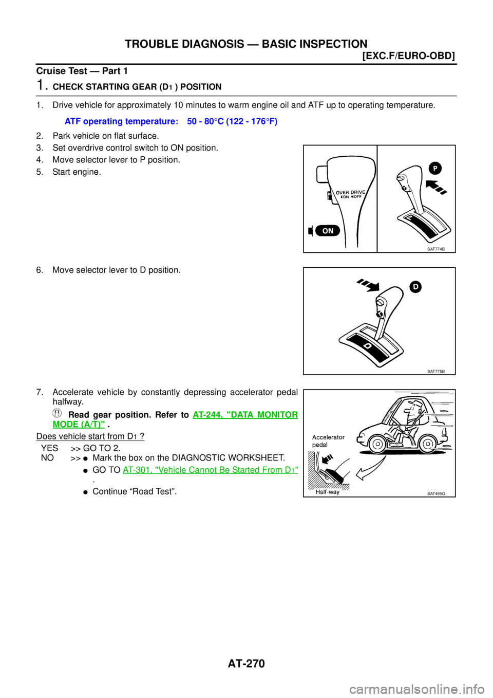
Cruise Test — Part 1
1. CHECK STARTING GEAR (D1 ) POSITION
1. Drive vehicle for approximately 10 minutes to warm engine oil and ATF up to operating temperature.
2. Park vehicle on flat surface.
3. Set overdrive control switch to ON position.
4. Move selector lever to P position.
5. Start engine.
6. Move selector lever to D position.
7. Accelerate vehicle by constantly depressing accelerator pedal
halfway.
Read gear position. Refer to AT- 2 4 4 , "
DATA MONITOR
MODE (A/T)" .
Does vehicle start from D
1 ?
YES >> GO TO 2.
NO >>
�Mark the box on the DIAGNOSTIC WORKSHEET.
�GO TO AT- 3 0 1 , "Vehicle Cannot Be Started From D1"
.
�Continue “Road Test”. ATF operating temperature: 50 - 80°C (122 - 176°F)
SAT774B
SAT775B
SAT495G
Page 2311 of 4179
TROUBLE DIAGNOSIS — BASIC INSPECTION
AT-275
[EXC.F/EURO-OBD]
D
E
F
G
H
I
J
K
L
MA
B
AT
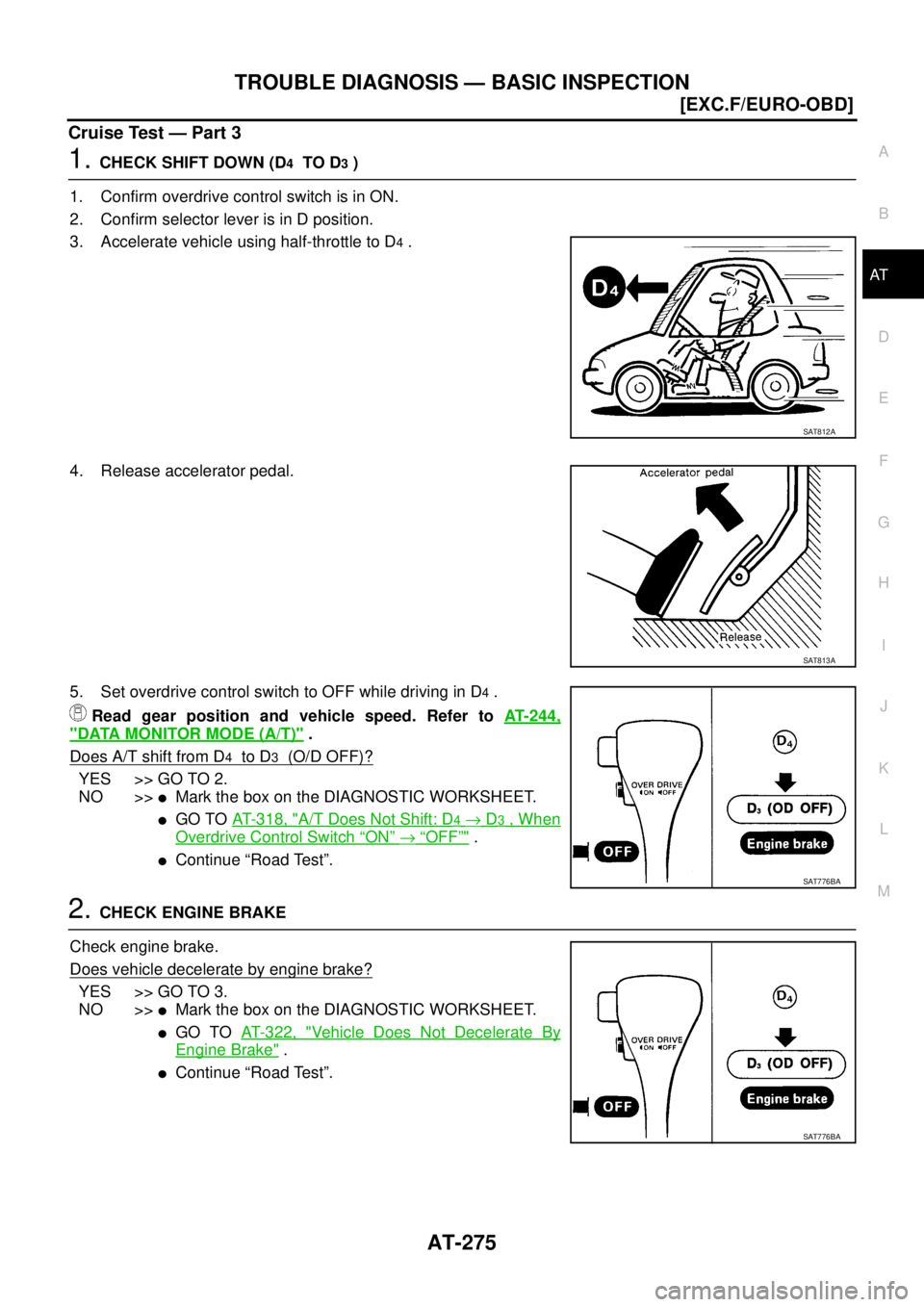
Cruise Test — Part 3
1. CHECK SHIFT DOWN (D4 TO D3 )
1. Confirm overdrive control switch is in ON.
2. Confirm selector lever is in D position.
3. Accelerate vehicle using half-throttle to D
4 .
4. Release accelerator pedal.
5. Set overdrive control switch to OFF while driving in D
4 .
Read gear position and vehicle speed. Refer to AT- 2 4 4 ,
"DATA MONITOR MODE (A/T)" .
Does A/T shift from D
4 to D3 (O/D OFF)?
YES >> GO TO 2.
NO >>
�Mark the box on the DIAGNOSTIC WORKSHEET.
�GO TO AT- 3 1 8 , "A/T Does Not Shift: D4 → D3 , When
Overdrive Control Switch “ON” → “OFF”" .
�Continue “Road Test”.
2. CHECK ENGINE BRAKE
Check engine brake.
Does vehicle decelerate by engine brake?
YES >> GO TO 3.
NO >>
�Mark the box on the DIAGNOSTIC WORKSHEET.
�GO TO AT- 3 2 2 , "Vehicle Does Not Decelerate By
Engine Brake" .
�Continue “Road Test”.
SAT812A
SAT813A
SAT776BA
SAT776BA
Page 2338 of 4179
AT-302
[EXC.F/EURO-OBD]
TROUBLE DIAGNOSES FOR SYMPTOMS
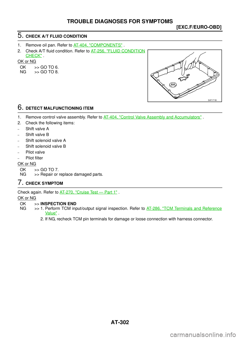
5. CHECK A/T FLUID CONDITION
1. Remove oil pan. Refer to AT- 4 0 4 , "
COMPONENTS" .
2. Check A/T fluid condition. Refer to AT- 2 5 6 , "
FLUID CONDITION
CHECK" .
OK or NG
OK >> GO TO 6.
NG >> GO TO 8.
6. DETECT MALFUNCTIONING ITEM
1. Remove control valve assembly. Refer to AT- 4 0 4 , "
Control Valve Assembly and Accumulators" .
2. Check the following items:
–Shift valve A
–Shift valve B
–Shift solenoid valve A
–Shift solenoid valve B
–Pilot valve
–Pilot filter
OK or NG
OK >> GO TO 7.
NG >> Repair or replace damaged parts.
7. CHECK SYMPTOM
Check again. Refer to AT- 2 7 0 , "
Cruise Test — Part 1" .
OK or NG
OK >>INSPECTION END
NG >> 1. Perform TCM input/output signal inspection. Refer to AT- 2 8 6 , "
TCM Terminals and Reference
Va l u e" .
2. If NG, recheck TCM pin terminals for damage or loose connection with harness connector.
SAT171B