RFD-30
REAR FINAL DRIVE ASSEMBLY
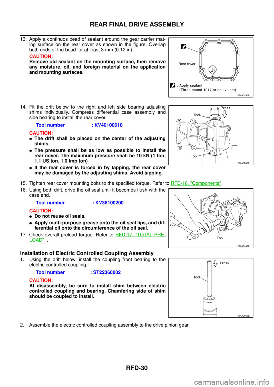
13. Apply a continuos bead of sealant around the gear carrier mat-
ing surface on the rear cover as shown in the figure. Overlap
both ends of the bead for at least 3 mm (0.12 in).
CAUTION:
Remove old sealant on the mounting surface, then remove
any moisture, oil, and foreign material on the application
and mounting surfaces.
14. Fit the drift below to the right and left side bearing adjusting
shims individually. Compress differential case assembly and
side bearing to install the rear cover.
CAUTION:
�The drift shall be placed on the center of the adjusting
shims.
�The pressure shall be as low as possible to install the
rear cover. The maximum pressure shall be 10 kN (1 ton,
1.1 US ton, 1.0 Imp ton)
�If the rear cover is forced in by tapping, the rear cover
may be damaged by the adjusting shims. Avoid tapping.
15. Tighten rear cover mounting bolts to the specified torque. Refer to RFD-16, "
Components" .
16. Using both drift, drive the oil seal until it becomes flush with the
case end.
CAUTION:
�Do not reuse oil seals.
�Apply multi-purpose grease onto the oil seal lips, and dif-
ferential oil onto the circumference of the oil seal.
17. Check overall preload torque. Refer to RFD-17, "
TOTAL PRE-
LOAD" .
Installation of Electric Controlled Coupling Assembly
1. Using the drift below, install the coupling front bearing to the
electric controlled coupling.
CAUTION:
At disassembly, be sure to install shim between electric
controlled coupling and bearing. Chamfering side of shim
should be coupled to install.
2. Assemble the electric controlled coupling assembly to the drive pinion gear.
PDIA0240E
Tool number : KV40100610
PDIA0065E
Tool number : KV38100200
PDIA0448E
Tool number : ST22360002
PDIA0060E
REAR FINAL DRIVE ASSEMBLY
RFD-31
C
E
F
G
H
I
J
K
L
MA
B
RFD
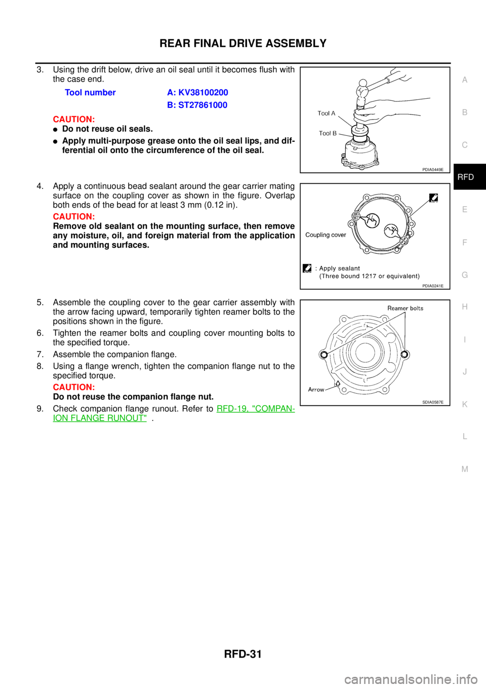
3. Using the drift below, drive an oil seal until it becomes flush with
the case end.
CAUTION:
�Do not reuse oil seals.
�Apply multi-purpose grease onto the oil seal lips, and dif-
ferential oil onto the circumference of the oil seal.
4. Apply a continuous bead sealant around the gear carrier mating
surface on the coupling cover as shown in the figure. Overlap
both ends of the bead for at least 3 mm (0.12 in).
CAUTION:
Remove old sealant on the mounting surface, then remove
any moisture, oil, and foreign material from the application
and mounting surfaces.
5. Assemble the coupling cover to the gear carrier assembly with
the arrow facing upward, temporarily tighten reamer bolts to the
positions shown in the figure.
6. Tighten the reamer bolts and coupling cover mounting bolts to
the specified torque.
7. Assemble the companion flange.
8. Using a flange wrench, tighten the companion flange nut to the
specified torque.
CAUTION:
Do not reuse the companion flange nut.
9. Check companion flange runout. Refer to RFD-19, "
COMPAN-
ION FLANGE RUNOUT" . Tool number A: KV38100200
B: ST27861000
PDIA0449E
PDIA0241E
SDIA0587E