Page 3576 of 4179

MA-16
PERIODIC MAINTENANCE
Maintenance operation: Check = Check and correct or replace as necessary.
Driving conditionMaintenance itemMainte-
nance
opera-
tionMaintenance intervalRefer-
ence
page
A
...........Air cleaner filterPetrol models ReplaceEvery 30,000 km
(18,000 miles) MA-23
Diesel models ReplaceEvery 30,000 km
(18,000 miles) MA-32
ABCD
........Engine oil &
engine oil filter Petrol models ReplaceEvery 7,500 km (4,500
miles) MA-23
,
MA-25
Diesel models ReplaceEvery 10,000 km (6,000
miles) MA-33,
MA-33
A...E.......Fuel filter Diesel models Check &
drain
waterEvery 10,000 km (6,000
miles) FL-17
ReplaceEvery 30,000 km
(18,000 miles) MA-31
.....F......Brake fluidPetrol models ReplaceEvery 30,000 km
(18,000 miles) MA-42Diesel models ReplaceEvery 30,000 km
(18,000 miles) MA-42
..C
....H
....Differential gear
oilPetrol models ReplaceEvery 30,000 km
(18,000 miles) MA-40Diesel models ReplaceEvery 30,000 km
(18,000 miles) MA-40
..C....H....Automatic tran-
saxle fluidPetrol models ReplaceEvery 60,000 km
(36,000 miles) MA-39
......GH....Steering gear &
linkage, axle &
suspension
parts, propeller
shaft, front drive
shafts & exhaust
systemPetrol models InspectEvery 30,000 km
(18,000 miles) MA-43
,
MA-44
,
MA-40
,
MA-45
,
MA-37
Diesel models InspectEvery 30,000 km
(18,000 miles) MA-43
,
MA-44
,
MA-40
,
MA-45
,
MA-37
A.C...GHI...Brake pads,
rotors & other
brake compo-
nentsPetrol models InspectEvery 15,000 km (9,000
miles) MA-43
,
MA-43
,
MA-43
Diesel models InspectEvery 10,000 km (6,000
miles) MA-43
,
MA-43
,
MA-43
A...........Ventilation air fil-
terPetrol models ReplaceEvery 15,000 km (9,000
miles) ATC-130
Diesel models ReplaceEvery 10,000 km (6,000
miles) ATC-130
Page 3577 of 4179

RECOMMENDED FLUIDS AND LUBRICANTSMA-17
C
DE
F
G H
I
J
K
M A
B
MA
RECOMMENDED FLUIDS AND LUBRICANTSPFP:00000
Fluids and LubricantsELS000C8
*1: For further details, see “SAE Viscosity Number”.
*2: Never use API CG-4.
*3: Use Genuine Nissan Anti-freeze Coolant (L250) or equivalent in its quality, in order to avoid possible aluminum corrosion w ithin the
engine cooling system caused by the use of non-genuine engine coolant.
Note that any repairs for the incidents within the engine cooling system while using non-genuine engine coolant may not be
covered by the warranty even if such incidents occurred during the warranty period.
*4: Contact a Nissan dealership for more information regarding suitable fluids, including recommended brand(s) of DEXRON
TM III/MER-
CONTM Automatic Transmission Fluid.
*5: Never mix different types of fluids (DOT 3 and DOT 4). Capacity (Approximate)
Recommended Fluids/Lubricants
Liter Imp measure
Engine oil
Drain and refill With oil filter
change
QR20DE,
QR25DE
3.9 3-3/8 qt
�Gasoline engine
API SG, SH, SJ or SL *1
ILSAC grade GF-I, GF-II or GF-III *1
ACEA A2
�Diesel engine
API CF-4*1, *2
ACEA B1, B3, B4, B5*1, *2
YD22DDTi 5.2 4-5/8 qt
Without oil filter
change QR20DE,
QR25DE
3.5 3-1/8 qt
YD22DDTi 4.9 4-3/8 qt
Dry engine (engine overhaul) QR20DE,
QR25DE
4.5 4 qt
YD22DDTi 6.3 5-1/2 qt
Cooling system (with reservoir) QR20DE,
QR25DE
7.1 6-1/4 qt
�Genuine Nissan Anti-freeze Coolant (L250) or
equivalent in its quality*3
YD22DDTi 9.5 8-3/8 qt
Reservoir tank QR20DE,
QR25DE
0.6 1/2 qt
YD22DDTi 0.6 1/2 qt
Manual transaxle gear oil
2.3 4pt
�Genuine Nissan gear oil or API GL-4, Viscos-
ity SAE 75W-85
Transfer gear oil 0.31 1/2 pt
�API GL-5*1, Viscosity SAE 80W-90
Differential gear oil 0.55 1 pt
�API GL-5*1, Viscosity SAE 80W-90
Automatic transaxle fluid 8.5 7-1/2 qt Genuine Nissan ATF or equivalent*4
Power steering fluid — — DEXRON
TM III type ATF or equivalent
Brake and clutch fluid — —
�DOT 3 or DOT 4 (US FMVSS No. 116)*5
Multi-purpose grease — — NLGI No. 2 (Lithium soap base)
Page 3603 of 4179
CHASSIS AND BODY MAINTENANCE
MA-43
C
D
E
F
G
H
I
J
K
MA
B
MA
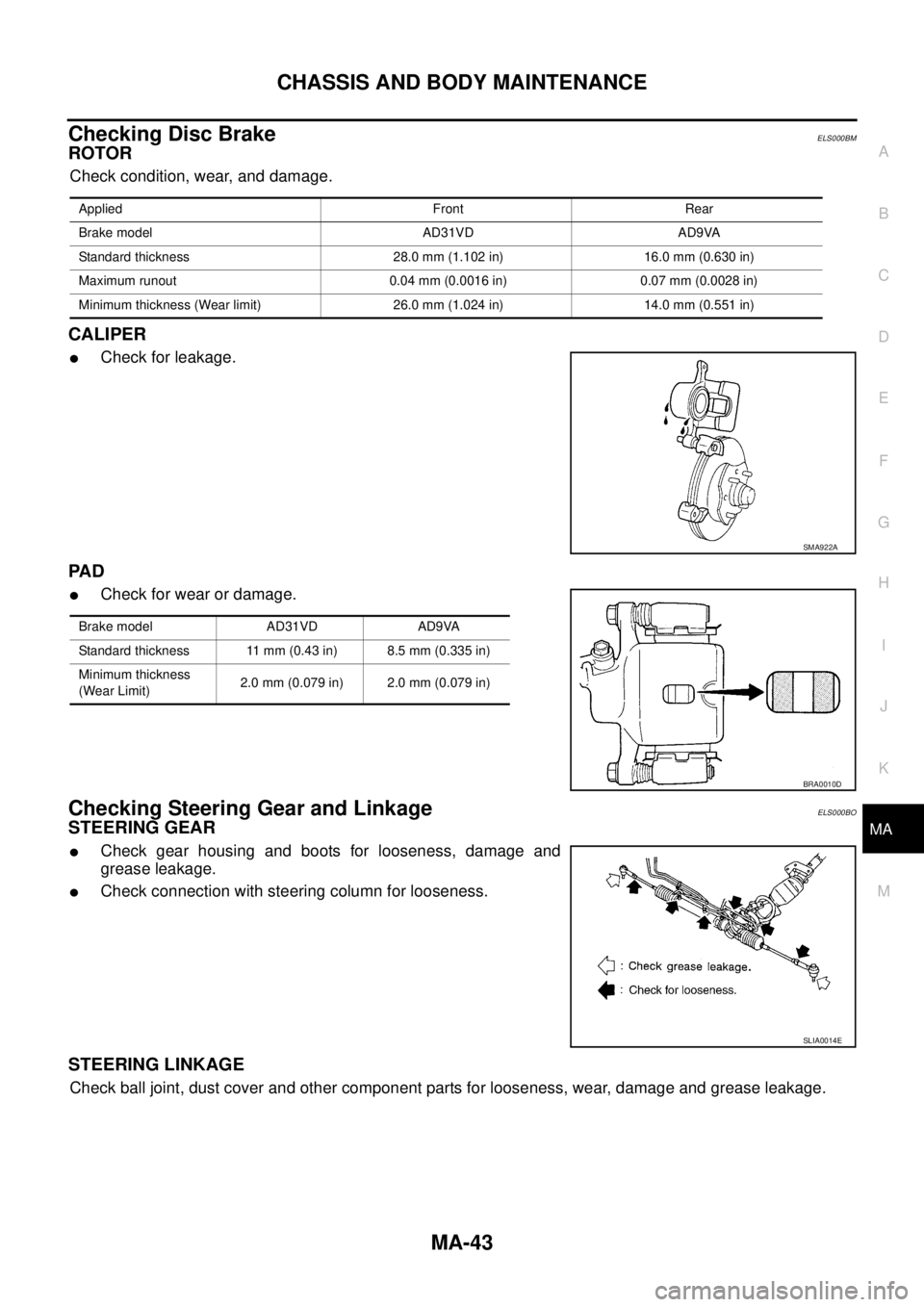
Checking Disc BrakeELS000BM
ROTOR
Check condition, wear, and damage.
CALIPER
�Check for leakage.
PA D
�Check for wear or damage.
Checking Steering Gear and LinkageELS000BO
STEERING GEAR
�Check gear housing and boots for looseness, damage and
grease leakage.
�Check connection with steering column for looseness.
STEERING LINKAGE
Check ball joint, dust cover and other component parts for looseness, wear, damage and grease leakage.
Applied Front Rear
Brake model AD31VD AD9VA
Standard thickness 28.0 mm (1.102 in) 16.0 mm (0.630 in)
Maximum runout 0.04 mm (0.0016 in) 0.07 mm (0.0028 in)
Minimum thickness (Wear limit) 26.0 mm (1.024 in) 14.0 mm (0.551 in)
SMA922A
Brake model AD31VD AD9VA
Standard thickness 11 mm (0.43 in) 8.5 mm (0.335 in)
Minimum thickness
(Wear Limit)2.0 mm (0.079 in) 2.0 mm (0.079 in)
BRA0010D
SLIA0014E
Page 3604 of 4179

MA-44
CHASSIS AND BODY MAINTENANCE
Checking Power Steering Fluid and LinesELS000BP
Check fluid level in reservoir tank with engine off.
Use “HOT” range at fluid temperatures of 50 to 80°C (122 to 176°F)
or “COLD” range at fluid temperatures of 0 to 30°C (32 to 86°F).
CAUTION:
�Do not overfill.
�Recommended fluid is DEXRONTM III type ATF or equiva-
lent.
Refer to MA-17, "
RECOMMENDED FLUIDS AND LUBRI-
CANTS"
�Check lines for improper attachment, leaks, cracks, dam-
age, loose connections, chafing and deterioration.
�Check rack boots for accumulation of power steering fluid.
Axle and Suspension PartsELS000BQ
Check front and rear axle and suspension parts for excessive play,
cracks, wear or other damage.
�Shake each wheel to check for excessive play.
�Check wheel bearings for smooth operation.
�Check axle and suspension nuts and bolts for looseness.
�Check strut (shock absorber) for oil leakage or other damage.
�Check suspension ball joint for grease leakage and ball joint
dust cover for cracks or other damage.
SST850C
SST851C
SMA525A
SFA392B
Page 3635 of 4179
HEATER UNIT
MTC-27
C
D
E
F
G
H
I
K
L
MA
B
MTC
HEATER UNITPFP:27100
Removal and InstallationEJS001F9
REMOVAL
1. Drain coolant from cooling system. Refer to CO-9, "Changing Engine Coolant" for QR engine or CO-31,
"Changing Engine Coolant" for YD engine.
2. Disconnect two heater hoses from heater core pipe.
3. Remove instrument panel. Refer to IP-11, "
Removal and Installation" .
4. Remove blower unit. Refer to ATC-125, "
BLOWER UNIT" .
5. Remove clips of vehicle harness from steering member.
6. Remove mounting nuts, and then remove instrument stay.
7. Remove mounting bolts from heater (& cooling) unit.
RJIA0060E
RJIA0061E
RJIA2444E
Page 3636 of 4179
MTC-28
HEATER UNIT
8. Remove steering member.
NOTE:
This illustration is for RHD models. The layout for LHD models is symmetrically opposite.
9. Remove heater unit.
INSTALLATION
Installation is basically the reverse order of removal.
NOTE:
When filling radiator with coolant, refer to CO-9, "
Changing Engine Coolant" for QR engine or CO-31, "Chang-
ing Engine Coolant" for YD engine.
RJIA2404E
Page 3684 of 4179

DI-6
COMBINATION METERS
�In a case that temperature detected by ambient sensor is lower than indicated temperature before turning
ignition switch off.
–Temperature detected by ambient sensor is indicated when turning ignition switch ON.
Indication During Running
Though temperature detected by ambient sensor temporarily changed, indicating temperature continentally
indicates.
�In a case that temperature detected by ambient sensor is higher than indicated temperature.
–If vehicle speed is more than 20 km/h(13 MPH), elevation of indicating temperature is limited according to
the speed until temperature detected by ambient sensor is indicated.
NOTE:
Vehicle speed 20 km/h (13 MPH): 256 sec., 25 km/h (16 MPH): 238 sec., 35 km/h (22 MPH): 200 sec., 50
km/h (31 MPH): 144 sec., 65 km/h (40 MPH): 88 sec., more than 80 km/h (50 MPH): 32 sec.
–If vehicle speed is more than 20 km/h (13 MPH), and that temperature detected by ambient sensor
becomes 8 °C (46 °F) more than indicating temperature, indicating temperature will be elevated unit the
degree becomes same as temperature detected by ambient sensor with limiting elevation of indicating
temperature 1 °C par a minute.
–If vehicle speed is less than 20 km/h (13 MPH), indicating temperature is continually kept.
�In a case that temperature detected by ambient sensor is lower than indicated temperature.
–Temperature detected by ambient sensor is indicated during running.
CAN CommunicationEKS00EH0
CAN (Controller Area Network) is a serial communication line for real time application. It is an on-vehicle mul-
tiplex communication line with high data communication speed and excellent error detection ability. Many elec-
tronic control units are equipped onto a vehicle, and each control unit shares information and links with other
control units during operation (not independent). In CAN communication, control units are connected with 2
communication lines (CAN H line, CAN L line) allowing a high rate of information transmission with less wiring.
Each control unit transmits/receives data but selectively reads required data only.
CAN Communication UnitEKS00F58
×: ApplicableBody typeWagon
Axle4WD
Engine QR20DE/QR25DE QR25DE YD22DDTi QR25DE
Transmission M/T A/T M/T A/T
Brake control ABS ESP
CAN communication unit
ECM×××××
TCM××
ABS actuator and electric unit (control unit)××
ESP/TCS/ABS control unit×××
Steering angle sensor×××
4WD control unit×××××
Combination meter×××××
CAN communication typeDI-7, "
TYPE 1"DI-8, "TYPE 2"DI-9, "TYPE 3/TYPE4"DI-10, "TYPE
5"
Page 3687 of 4179
COMBINATION METERS
DI-9
C
D
E
F
G
H
I
J
L
MA
B
DI
TYPE 3/TYPE4
System diagram
Input/output signal chart
T: Transmit R: Receive
*1: YD engine models only
*2: QR engine models only
PKIA6459E
Signals ECMESP/TCS/ABS
control unitSteering angle
sensor4WD control
unitCombination
meter
Engine speed signal T R R R
Engine coolant temperature signal TR
A/C switch signal*
1RT
A/C compressor feedback signal*
2TR
Vehicle speed signalTRR
RT
ABS warning lamp signal T R
Brake warning lamp signal T R
SLIP indicator lamp signal T R
ESP OFF indicator lamp signal T R
4WD warning lamp signalTR
4WD mode indicator lamp signalTR
Parking brake switch signalRT
MI signal TR
Glow indicator lamp signal*
1TR