Page 3589 of 4179
ENGINE MAINTENANCE (YD22DDTI)
MA-29
C
D
E
F
G
H
I
J
K
MA
B
MA
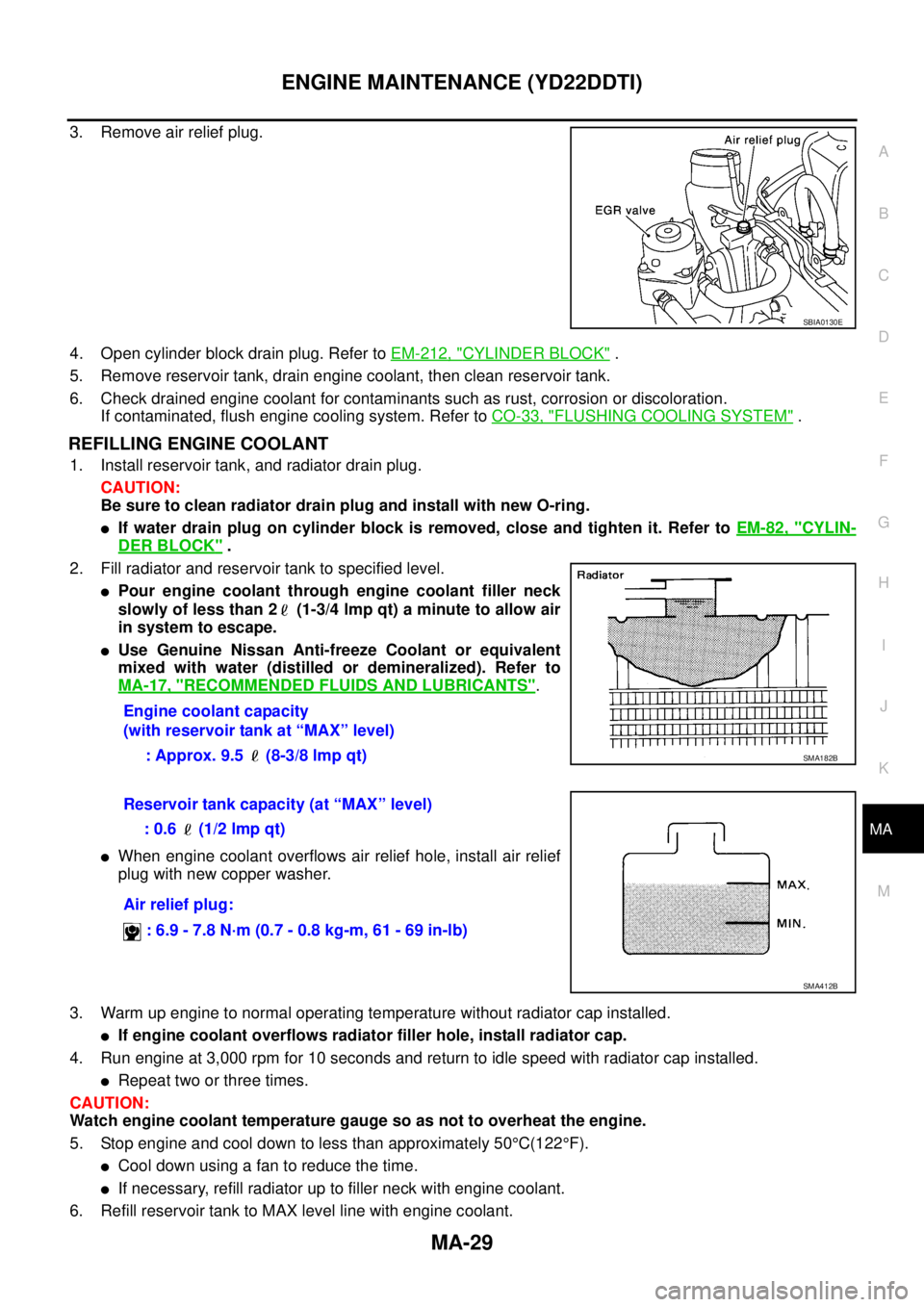
3. Remove air relief plug.
4. Open cylinder block drain plug. Refer to EM-212, "
CYLINDER BLOCK" .
5. Remove reservoir tank, drain engine coolant, then clean reservoir tank.
6. Check drained engine coolant for contaminants such as rust, corrosion or discoloration.
If contaminated, flush engine cooling system. Refer to CO-33, "
FLUSHING COOLING SYSTEM" .
REFILLING ENGINE COOLANT
1. Install reservoir tank, and radiator drain plug.
CAUTION:
Be sure to clean radiator drain plug and install with new O-ring.
�If water drain plug on cylinder block is removed, close and tighten it. Refer to EM-82, "CYLIN-
DER BLOCK" .
2. Fill radiator and reservoir tank to specified level.
�Pour engine coolant through engine coolant filler neck
slowly of less than 2 (1-3/4 lmp qt) a minute to allow air
in system to escape.
�Use Genuine Nissan Anti-freeze Coolant or equivalent
mixed with water (distilled or demineralized). Refer to
MA-17, "
RECOMMENDED FLUIDS AND LUBRICANTS".
�When engine coolant overflows air relief hole, install air relief
plug with new copper washer.
3. Warm up engine to normal operating temperature without radiator cap installed.
�If engine coolant overflows radiator filler hole, install radiator cap.
4. Run engine at 3,000 rpm for 10 seconds and return to idle speed with radiator cap installed.
�Repeat two or three times.
CAUTION:
Watch engine coolant temperature gauge so as not to overheat the engine.
5. Stop engine and cool down to less than approximately 50°C(122°F).
�Cool down using a fan to reduce the time.
�If necessary, refill radiator up to filler neck with engine coolant.
6. Refill reservoir tank to MAX level line with engine coolant.
SBIA0130E
Engine coolant capacity
(with reservoir tank at “MAX” level)
: Approx. 9.5 (8-3/8 lmp qt)
SMA182B
Reservoir tank capacity (at “MAX” level)
: 0.6 (1/2 lmp qt)
Air relief plug:
: 6.9 - 7.8 N·m (0.7 - 0.8 kg-m, 61 - 69 in-lb)
SMA412B
Page 3590 of 4179
MA-30
ENGINE MAINTENANCE (YD22DDTI)
7. Repeat steps 2 through 5 two or more times with radiator cap installed until engine coolant level no longer
drops.
8. Check cooling system for leaks with engine running.
9. Warm up engine, and check for sound of engine coolant flow while running engine from idle up to 3,000
rpm with heater temperature controller set at several position between COOL and WARM.
�Sound may be noticeable at heater unit.
10. Repeat step 9 three times.
11. If sound is heard, bleed air from cooling system by repeating steps 2 through 5 until engine coolant level
no longer drops.
�Clean excess engine coolant from engine.
FLUSHING COOLING SYSTEM
1. Fill radiator with water until water spills from the air relief hole, then close air relief flag. Fill radiator and
reservoir tank with water and reinstall radiator cap.
2. Run engine and warm it up to normal operating temperature.
3. Rev engine two or three times under no-load.
4. Stop engine and wait until it cools down.
5. Drain water from the system. Refer to MA-28, "
DRAINING ENGINE COOLANT" .
6. Repeat steps 1 through 5 until clear water begins to drain from radiator.
Checking Cooling SystemELS000C4
WARNING:
Never remove the radiator cap when the engine is hot. Serious burns could occur from high pressure
engine coolant escaping from the radiator. Wrap a thick cloth around the cap. Slowly turn it a quarter
turn to allow built-up pressure to escape. Carefully remove the cap by turning it all the way.
CHECKING COOLING SYSTEM HOSES
Check hoses for improper attachment, leaks, cracks, damage, loose connections, chafing and deterioration.
CHECKING RADIATOR
Check radiator for mud or clogging. If necessary, clean radiator as follows.
�Be careful not to bend or damage the radiator fins.
�When radiator is cleaned without removal, remove all surrounding parts such as cooling fan, radiator
shroud and horns. Then tape the harness and connectors to prevent water from entering.
1. Apply water by hose to the back side of the radiator core vertically downwards.
2. Apply water again to all radiator core surface once per minute.
3. Stop washing if any stains no longer flow out from the radiator.
4. Blow air into the back side of radiator core vertically downwards.
�Use compressed air lower than 490 kpa (4.9 bar, 5 kg/cm2 , 71psi) and keep distance more than 30
cm(11.8 in).
5. Blow air again into all the radiator core surface once per minute until no water sprays out.
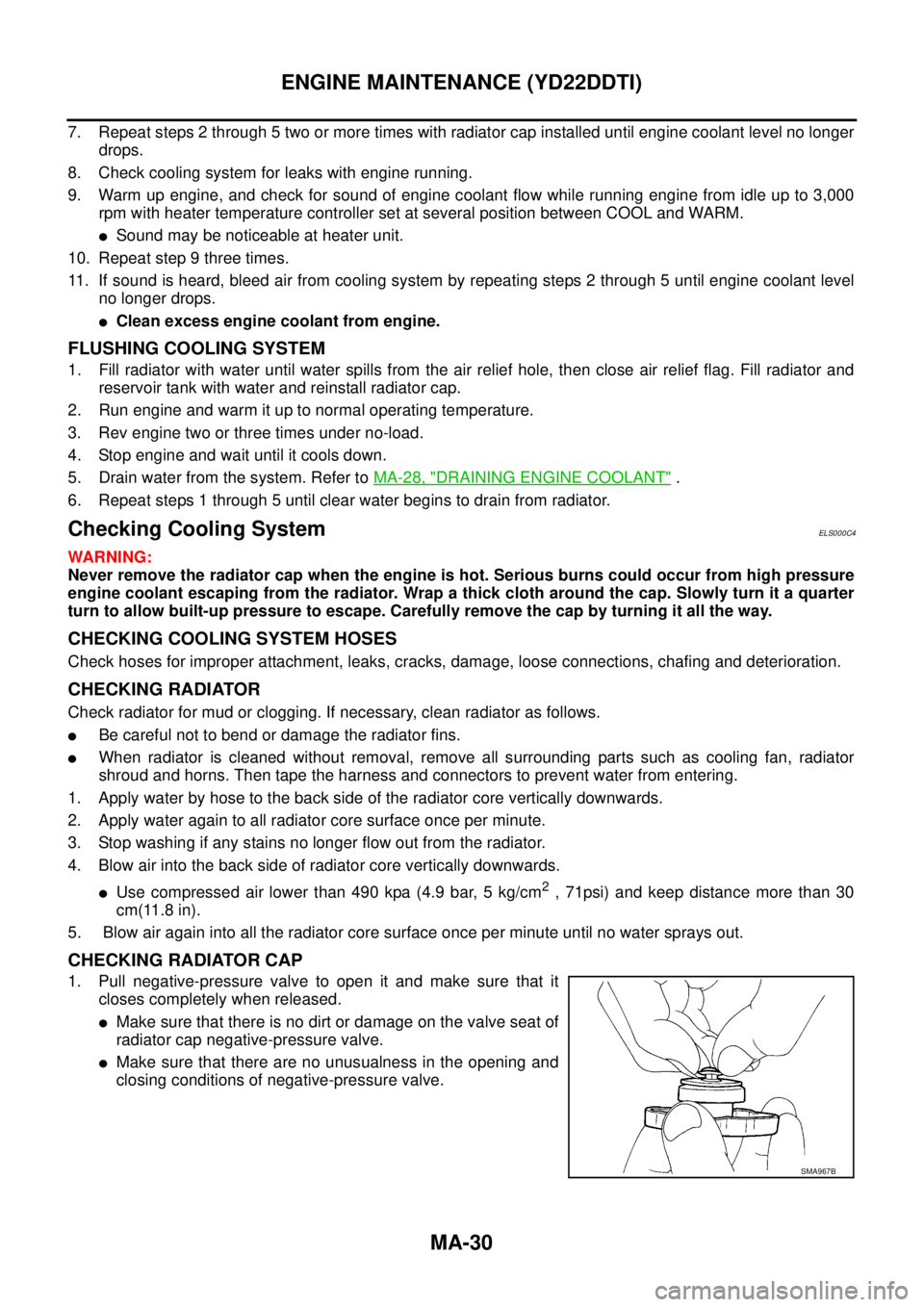
CHECKING RADIATOR CAP
1. Pull negative-pressure valve to open it and make sure that it
closes completely when released.
�Make sure that there is no dirt or damage on the valve seat of
radiator cap negative-pressure valve.
�Make sure that there are no unusualness in the opening and
closing conditions of negative-pressure valve.
SMA967B
Page 3682 of 4179
DI-4
COMBINATION METERS
COMBINATION METERSPFP:24814
System DescriptionEKS00EGZ
UNIFIED CONTROL METER
�Speedometer, odo/trip meter, tachometer, fuel gauge and water temperature gauge are controlled by the
unified meter control unit, which is built into the combination meter.
�Digital meter is adopted for odo/trip meter.*
*The record of the odo meter is kept even if the battery cable is disconnected. The record of the trip meter
is erased when the battery cable is disconnected.
�Odo/trip meter segments can be checked in diagnosis mode.
�Meter/gauge can be checked in diagnosis mode.
HOW TO CHANGE THE DISPLAY FOR ODO/TRIP METER
�The vehicle speed signal and the memory signals from the meter memory circuit are processed by the
combination meter and the mileage is displayed.
�Ambient temperature indicator indicates signal from ambient sensor processed by combination meter.
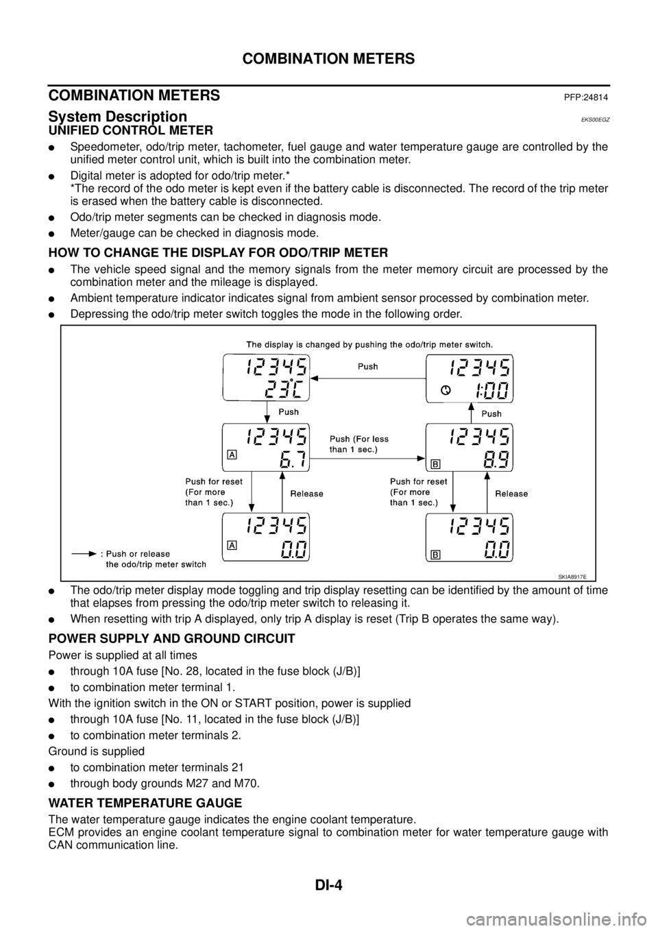
�Depressing the odo/trip meter switch toggles the mode in the following order.
�The odo/trip meter display mode toggling and trip display resetting can be identified by the amount of time
that elapses from pressing the odo/trip meter switch to releasing it.
�When resetting with trip A displayed, only trip A display is reset (Trip B operates the same way).
POWER SUPPLY AND GROUND CIRCUIT
Power is supplied at all times
�through 10A fuse [No. 28, located in the fuse block (J/B)]
�to combination meter terminal 1.
With the ignition switch in the ON or START position, power is supplied
�through 10A fuse [No. 11, located in the fuse block (J/B)]
�to combination meter terminals 2.
Ground is supplied
�to combination meter terminals 21
�through body grounds M27 and M70.
WATER TEMPERATURE GAUGE
The water temperature gauge indicates the engine coolant temperature.
ECM provides an engine coolant temperature signal to combination meter for water temperature gauge with
CAN communication line.
SKIA8917E
Page 3685 of 4179
COMBINATION METERS
DI-7
C
D
E
F
G
H
I
J
L
MA
B
DI
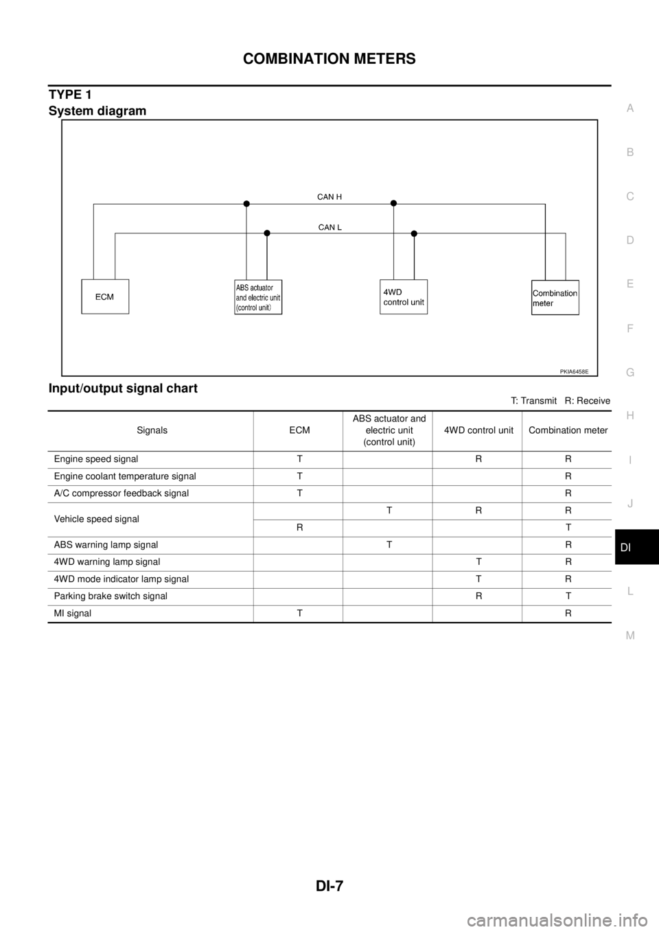
TYPE 1
System diagram
Input/output signal chart
T: Transmit R: Receive
PKIA6458E
Signals ECMABS actuator and
electric unit
(control unit)4WD control unit Combination meter
Engine speed signal T R R
Engine coolant temperature signal T R
A/C compressor feedback signal T R
Vehicle speed signalTRR
RT
ABS warning lamp signal T R
4WD warning lamp signalTR
4WD mode indicator lamp signal T R
Parking brake switch signalRT
MI signal T R
Page 3686 of 4179
DI-8
COMBINATION METERS
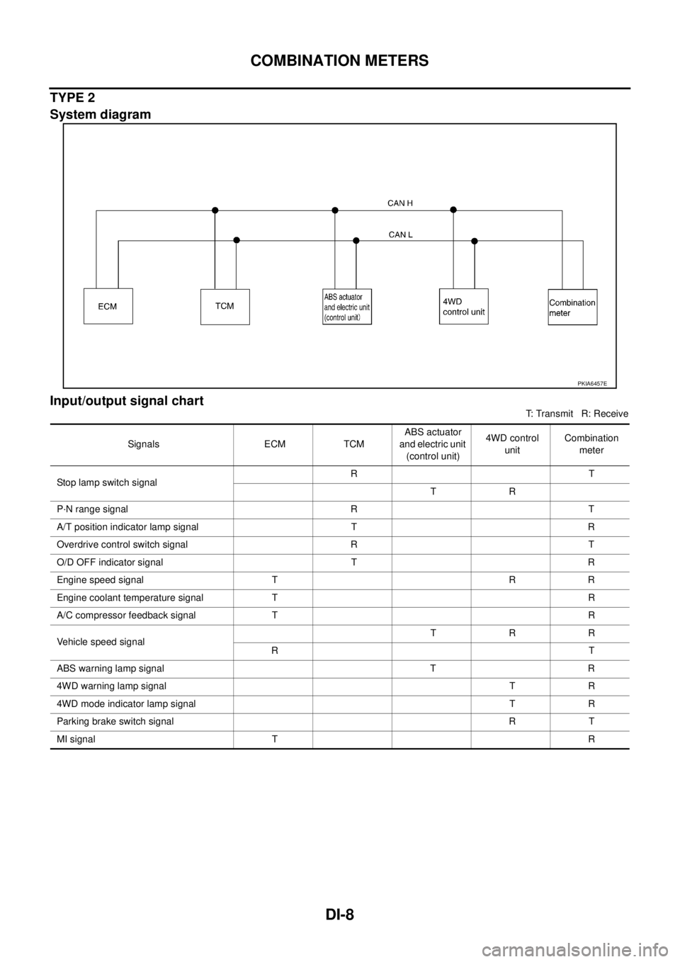
TYPE 2
System diagram
Input/output signal chart
T: Transmit R: Receive
PKIA6457E
Signals ECM TCMABS actuator
and electric unit
(control unit)4WD control
unitCombination
meter
Stop lamp switch signalRT
TR
P·N range signal R T
A/T position indicator lamp signal T R
Overdrive control switch signal R T
O/D OFF indicator signal T R
Engine speed signal T R R
Engine coolant temperature signal TR
A/C compressor feedback signal TR
Vehicle speed signalTRR
RT
ABS warning lamp signal T R
4WD warning lamp signalTR
4WD mode indicator lamp signalTR
Parking brake switch signalRT
MI signal TR
Page 3687 of 4179
COMBINATION METERS
DI-9
C
D
E
F
G
H
I
J
L
MA
B
DI
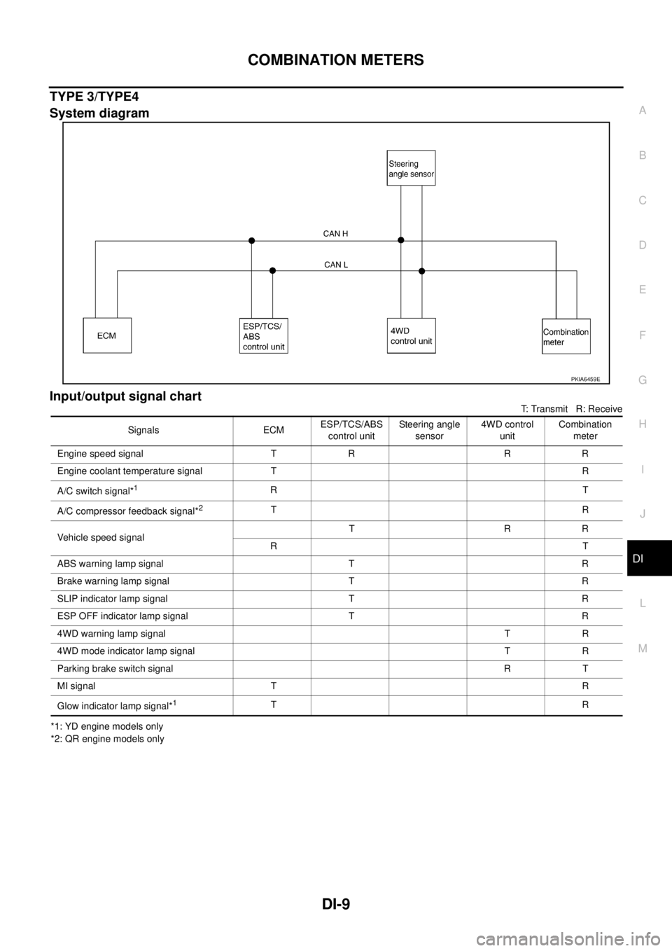
TYPE 3/TYPE4
System diagram
Input/output signal chart
T: Transmit R: Receive
*1: YD engine models only
*2: QR engine models only
PKIA6459E
Signals ECMESP/TCS/ABS
control unitSteering angle
sensor4WD control
unitCombination
meter
Engine speed signal T R R R
Engine coolant temperature signal TR
A/C switch signal*
1RT
A/C compressor feedback signal*
2TR
Vehicle speed signalTRR
RT
ABS warning lamp signal T R
Brake warning lamp signal T R
SLIP indicator lamp signal T R
ESP OFF indicator lamp signal T R
4WD warning lamp signalTR
4WD mode indicator lamp signalTR
Parking brake switch signalRT
MI signal TR
Glow indicator lamp signal*
1TR
Page 3688 of 4179
DI-10
COMBINATION METERS
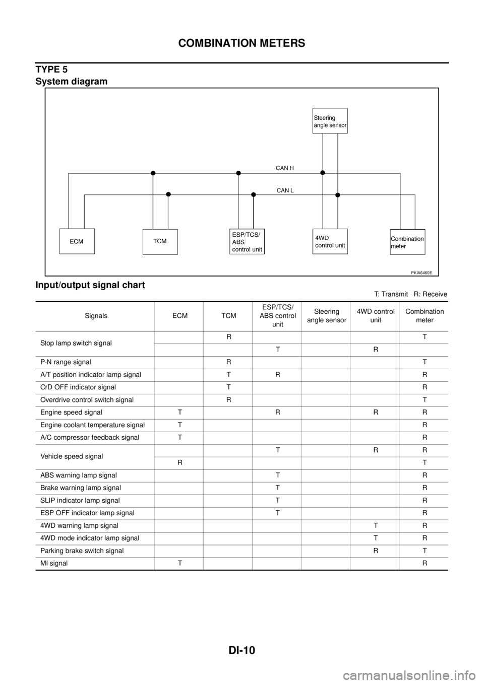
TYPE 5
System diagram
Input/output signal chart
T: Transmit R: Receive
PKIA6460E
Signals ECM TCMESP/TCS/
ABS control
unitSte ering
angle sensor4WD control
unitCombination
meter
Stop lamp switch signalRT
TR
P·N range signal R T
A/T position indicator lamp signal T R R
O/D OFF indicator signal T R
Overdrive control switch signal R T
Engine speed signal T R R R
Engine coolant temperature signal TR
A/C compressor feedback signal TR
Vehicle speed signalTRR
RT
ABS warning lamp signal T R
Brake warning lamp signal T R
SLIP indicator lamp signal T R
ESP OFF indicator lamp signal T R
4WD warning lamp signalTR
4WD mode indicator lamp signalTR
Parking brake switch signalRT
MI signal TR
Page 3782 of 4179
![NISSAN X-TRAIL 2003 Service Repair Manual LAN-4
[CAN]
CAN COMMUNICATION
CAN COMMUNICATIONPFP:23710
System DescriptionEKS001U3
CAN (Controller Area Network) is a serial communication line for real time application. It is an on-vehicle mul-
t](/manual-img/5/57404/w960_57404-3781.png "NISSAN X-TRAIL 2003 Service Repair Manual LAN-4
[CAN]
CAN COMMUNICATION
CAN COMMUNICATIONPFP:23710
System DescriptionEKS001U3
CAN (Controller Area Network) is a serial communication line for real time application. It is an on-vehicle mul-
t")
LAN-4
[CAN]
CAN COMMUNICATION
CAN COMMUNICATIONPFP:23710
System DescriptionEKS001U3
CAN (Controller Area Network) is a serial communication line for real time application. It is an on-vehicle mul-
tiplex communication line with high data communication speed and excellent error detection ability. Many elec-
tronic control units are equipped onto a vehicle, and each control unit shares information and links with other
control units during operation (not independent). In CAN communication, control units are connected with 2
communication lines (CAN H line, CAN L line) allowing a high rate of information transmission with less wiring.
Each control unit transmits/receives data but selectively reads required data only.
CAN Communication UnitEKS00EGL
Go to CAN system, when selecting your CAN system type from the following table.
TYPE 1
System diagram
Input/output signal chart
T: Transmit R: Receive Body typeWagon
Axle4WD
Engine QR20DE/QR25DE QR25DE YD22DDTi QR25DE
Transmission M/T A/T M/T A/T
Brake control ABS ESP
CAN system type 1 2 3 4 5
CAN system trouble diagnosisLAN-9
LAN-25LAN-50LAN-68LAN-86
PKIA6458E
Signals ECMABS actuator and
electric unit
(control unit)4WD control unit Combination meter
Stop lamp switch signal T R
Engine speed signal T R R
Engine coolant temperature signal T R
Accelerator pedal position signal T R
A/C compressor feedback signal T R
Vehicle speed signalTRR
RT