2003 NISSAN X-TRAIL brake sensor
[x] Cancel search: brake sensorPage 3687 of 4179

COMBINATION METERS
DI-9
C
D
E
F
G
H
I
J
L
MA
B
DI
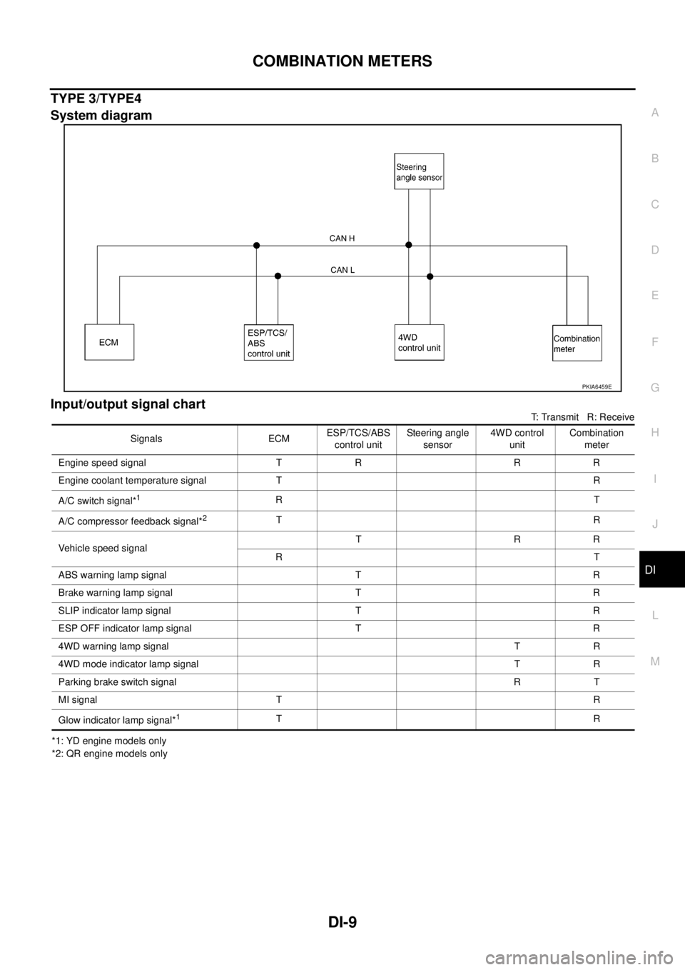
TYPE 3/TYPE4
System diagram
Input/output signal chart
T: Transmit R: Receive
*1: YD engine models only
*2: QR engine models only
PKIA6459E
Signals ECMESP/TCS/ABS
control unitSteering angle
sensor4WD control
unitCombination
meter
Engine speed signal T R R R
Engine coolant temperature signal TR
A/C switch signal*
1RT
A/C compressor feedback signal*
2TR
Vehicle speed signalTRR
RT
ABS warning lamp signal T R
Brake warning lamp signal T R
SLIP indicator lamp signal T R
ESP OFF indicator lamp signal T R
4WD warning lamp signalTR
4WD mode indicator lamp signalTR
Parking brake switch signalRT
MI signal TR
Glow indicator lamp signal*
1TR
Page 3688 of 4179

DI-10
COMBINATION METERS
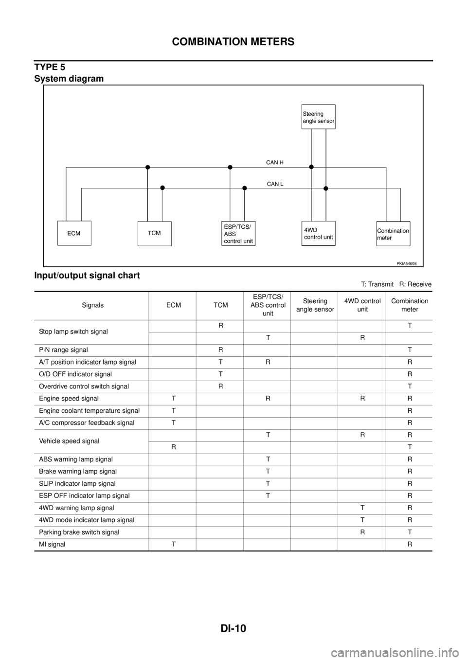
TYPE 5
System diagram
Input/output signal chart
T: Transmit R: Receive
PKIA6460E
Signals ECM TCMESP/TCS/
ABS control
unitSte ering
angle sensor4WD control
unitCombination
meter
Stop lamp switch signalRT
TR
P·N range signal R T
A/T position indicator lamp signal T R R
O/D OFF indicator signal T R
Overdrive control switch signal R T
Engine speed signal T R R R
Engine coolant temperature signal TR
A/C compressor feedback signal TR
Vehicle speed signalTRR
RT
ABS warning lamp signal T R
Brake warning lamp signal T R
SLIP indicator lamp signal T R
ESP OFF indicator lamp signal T R
4WD warning lamp signalTR
4WD mode indicator lamp signalTR
Parking brake switch signalRT
MI signal TR
Page 3784 of 4179
![NISSAN X-TRAIL 2003 Service Repair Manual LAN-6
[CAN]
CAN COMMUNICATION
TYPE 3/TYPE4
System diagram
Input/output signal chart
T: Transmit R: Receive 4WD warning lamp signalTR
4WD mode indicator lamp signalTR
Parking brake switch signalRT
NISSAN X-TRAIL 2003 Service Repair Manual LAN-6
[CAN]
CAN COMMUNICATION
TYPE 3/TYPE4
System diagram
Input/output signal chart
T: Transmit R: Receive 4WD warning lamp signalTR
4WD mode indicator lamp signalTR
Parking brake switch signalRT](/manual-img/5/57404/w960_57404-3783.png)
LAN-6
[CAN]
CAN COMMUNICATION
TYPE 3/TYPE4
System diagram
Input/output signal chart
T: Transmit R: Receive 4WD warning lamp signalTR
4WD mode indicator lamp signalTR
Parking brake switch signalRT
MI signal TR
Engine A/T integrated control signalTR
RT
A/T self-diagnosis signal R TSignals ECM TCMABS actuator
and electric unit
(control unit)4WD control
unitCombination
meter
PKIA9634E
Signals ECMESP/TCS/ABS
control unitSteering angle
sensor4WD control
unitCombination
meter
Stop lamp switch signal T R
Engine speed signal T R R R
Engine coolant temperature signal TR
Accelerator pedal position signal T R R
A/C switch signal*
1RT
A/C compressor feedback signal*
2TR
Vehicle speed signalTRR
RT
ABS warning lamp signal T R
Brake warning lamp signal T R
SLIP indicator lamp signal T R
ESP OFF indicator lamp signal T R
4WD warning lamp signalTR
4WD mode indicator lamp signalTR
Parking brake switch signalRT
Page 3785 of 4179
![NISSAN X-TRAIL 2003 Service Repair Manual CAN COMMUNICATION
LAN-7
[CAN]
C
D
E
F
G
H
I
J
L
MA
B
LAN
*1: YD engine models only
*2: QR engine models only
TYPE 5
System diagram
Input/output signal chart
T: Transmit R: Receive MI signal TR
Glo NISSAN X-TRAIL 2003 Service Repair Manual CAN COMMUNICATION
LAN-7
[CAN]
C
D
E
F
G
H
I
J
L
MA
B
LAN
*1: YD engine models only
*2: QR engine models only
TYPE 5
System diagram
Input/output signal chart
T: Transmit R: Receive MI signal TR
Glo](/manual-img/5/57404/w960_57404-3784.png)
CAN COMMUNICATION
LAN-7
[CAN]
C
D
E
F
G
H
I
J
L
MA
B
LAN
*1: YD engine models only
*2: QR engine models only
TYPE 5
System diagram
Input/output signal chart
T: Transmit R: Receive MI signal TR
Glow indicator lamp signal*
1TR
Steering angle sensor signal R TSignals ECMESP/TCS/ABS
control unitSteering angle
sensor4WD control
unitCombination
meter
PKIA9635E
Signals ECM TCMESP/TCS/
ABS control
unitSteering
angle sensor4WD control
unitCombination
meter
Stop lamp switch signalRT
TR
P·N range signal R T
A/T position indicator lamp signal T R R
O/D OFF indicator signal T R
Overdrive control switch signal R T
Closed throttle position signal T R
Wide open throttle position signal T R
Engine speed signal T R R R
Engine coolant temperature signal TR
Accelerator pedal position signal T R R
Output shaft revolution signal R T
A/C compressor feedback signal TR
Vehicle speed signalTRR
RT
ABS warning lamp signal T R
Brake warning lamp signal T R
Page 3786 of 4179
![NISSAN X-TRAIL 2003 Service Repair Manual LAN-8
[CAN]
CAN COMMUNICATION
SLIP indicator lamp signal T R
ESP OFF indicator lamp signal T R
4WD warning lamp signalTR
4WD mode indicator lamp signalTR
Parking brake switch signalRT
MI signal TR
S NISSAN X-TRAIL 2003 Service Repair Manual LAN-8
[CAN]
CAN COMMUNICATION
SLIP indicator lamp signal T R
ESP OFF indicator lamp signal T R
4WD warning lamp signalTR
4WD mode indicator lamp signalTR
Parking brake switch signalRT
MI signal TR
S](/manual-img/5/57404/w960_57404-3785.png)
LAN-8
[CAN]
CAN COMMUNICATION
SLIP indicator lamp signal T R
ESP OFF indicator lamp signal T R
4WD warning lamp signalTR
4WD mode indicator lamp signalTR
Parking brake switch signalRT
MI signal TR
Steering angle sensor signal R T
Engine and A/T integratedTR
RT
A/T self-diagnosis signal R TSignals ECM TCMESP/TCS/
ABS control
unitSteering
angle sensor4WD control
unitCombination
meter
Page 4063 of 4179

HARNESS
PG-61
C
D
E
F
G
H
I
J
L
MA
B
PG
Wiring Diagram Codes (Cell Codes) EKS0032J
Use the chart below to find out what each wiring diagram code stands for.
Refer to the wiring diagram code in the alphabetical index to find the location (page number) of each wiring
diagram.
Code Section Wiring Diagram Name
1STSIG AT A/T 1st Signal
2NDSIG AT A/T 2nd Signal
3RDSIG AT A/T 3rd Signal
4THSIG AT A/T 4th Signal
4WD TF 4WD Control system
A/C ATC Air Conditioner
ABS BRC Anti-Lock Brake System
APP1PW EC Accelerator Pedal Position Sensor 1 Power Supply
APP2PW EC Accelerator Pedal Position Sensor 2 Power Supply
APPS1 EC Accelerator Pedal Position Sensor
APPS2 EC Accelerator Pedal Position Sensor
APPS3 EC Accelerator Pedal Position Sensor
AT/IND DI A/T Indicator
AUDIO AV Audio
BA/FTS AT A/T Fluid Temperature Sensor and TCM Power Supply
BACK/L LT Back-Up Lamp
BOOST EC Turbocharger Boost Sensor
BRK/SW EC Brake Switch
CAN AT CAN Communication Line
CAN EC CAN Communication Line
CAN LAN CAN System
CHARGE SC Charging System
CHIME DI Warning Chime
CIGAR WW Cigarette Lighter
CLOCK DI Clock
CKPS EC Crankshaft Position Sensor
CMPS EC Camshaft Position Sensor
COOL/F EC Cooling Fan Control
D/LOCK BL Power Door Lock
DEF GW Rear Window Defogger
DTRL LT Headlamp - With Daytime Light System
ECM/PW EC ECM Power Supply for Back-Up
ECMRLY EC ECM Relay
ECTS EC Engine Coolant Temperature Sensor
EGVC/V EC EGR Volume Control Valve
EGRVLV EC EGR Volume Control Valve
ENGSS AT Engine Speed Signal
ESP BRC ESP/TCS/ABS Control System
ETC1 EC Electric Throttle Control Function
ETC2 EC Electric Throttle Control Motor Relay
ETC3 EC Electric Throttle Control Motor
Page 4172 of 4179

IDX-2
ALPHABETICAL INDEX
Numerics
4WD - Wiring diagram ....................................... TF-21
4WD control unit inspection table ...................... TF-28
A
A/C air flow ......................................... ATC-32
, MTC-5
A/C component layout ..................................... ATC-23
A/C compressor clutch removal and installation ...........
ATC-146
A/C compressor precaution ............................. ATC-10
A/C compressor special service tool ................ ATC-14
A/C diagnostic work flow (auto A/C) ................ ATC-34
A/C HFC134a (R134a) system precaution ........ ATC-4
A/C HFC134a (R134a) system service procedure .......
ATC-141
A/C HFC134a (R134a) system service tools ... ATC-15
A/C HFC134a system service equipment precaution ...
ATC-10
A/C lubricant (R134a) ...................................... ATC-24
A/C operational check ......................... ATC-65, MTC-7
A/C performance test diagnoses ..................... ATC-98
A/C reray .......................................................... ATC-94
A/C self-diagnoses (auto A/C) ......................... ATC-57
A/C system description (auto A/C) ................... ATC-27
A/C trouble diagnoses (auto A/C) ....... ATC-34, MTC-3
A/C, A - Wiring diagram ................................... ATC-39
A/T fluid checking .................................. AT-16, MA-38
A/T fluid replacement ............................. AT-17, MA-39
A/T fluid temperature sensor ........................... AT-111
A/T IND - Wiring diagram .................................... DI-51
A/T indicator ........................................................ DI-51
A/T shift lock system ........................................ AT-398
A/T shift lock system - Wiring diagram ............ AT-399
A/T trouble diagnoses .......................... AT-57, AT-251
A/T Wiring diagram AT - 1ST ........................... AT-127
A/T Wiring diagram AT - 2ND .......................... AT-132
A/T Wiring diagram AT - 3RD .......................... AT-137
A/T Wiring diagram AT - 4TH .......................... AT-143
A/T Wiring diagram AT - BA/FTS ..................... AT-376
A/T Wiring diagram AT - CAN .............. AT-98, AT-330
A/T Wiring diagram AT - ENG SS ...... AT-121, AT-383
A/T Wiring diagram AT - FTS .......................... AT-108
A/T Wiring diagram AT - LPSV .......... AT-156, AT-389
A/T Wiring diagram AT - MAIN ........................ AT-395
A/T Wiring diagram AT - OVRCSV .... AT-180, AT-364
A/T Wiring diagram AT - PNP/SW ................... AT-102
A/T Wiring diagram AT - SSV/A ......... AT-163, AT-352
A/T Wiring diagram AT - SSV/B ......... AT-169, AT-358
A/T Wiring diagram AT - TCV ............ AT-150, AT-370
A/T Wiring diagram AT - TPS ............ AT-175, AT-347
A/T Wiring diagram AT - VSS A/T ..... AT-114, AT-334
A/T Wiring diagram AT - VSSMTR .... AT-194, AT-341
Accelerator control system ............................... ACC-2
Accelerator pedal position (APP) sensor ........ EC-386,
EC-393
, EC-409, EC-740, EC-747, EC-763, EC-987,
EC-1025
, EC-1098, EC-1104, EC-1149, EC-1297,
EC-1332
, EC-1387, EC-1393, EC-1437
Accelerator pedal released position learning .... EC-45,
EC-507
Aiming adjustment ............................................... LT-4
Air bag .............................................................. SRS-3
Air bag disposal .............................................. SRS-42
Air bleeding (hydraulic clutch) .............................. CL-7
Air bleeding for brake system .............................. BR-9
Air cleaner and air duct(QR20DE•QR25DE) .... EM-15
Air cleaner and air duct(YD22DDTi) ............... EM-133
Air cleaner filter replacement(QR20DEQR25DE) ........
MA-23
Air cleaner filter replacement(YD22DDTi) ......... MA-32
Air cleaner filter(QR20DEQR25DE) ................ EM-15
Air cleaner filter(YD22DDTi) ........................... EM-133
Air conditioner cut control .... EC-37, EC-499, EC-887,
EC-1218
Air flow meter - See Mass air flow sensor ....... EC-149,
EC-590
Air mix door control linkage adjustment ......... ATC-78,
ATC-135
, MTC-10, MTC-32
Air mix. door motor ......................... ATC-76, ATC-135
Air spoiler, rear ................................................... EI-30
Alternator ........................................................... SC-12
Ambient sensor ............. ATC-109, ATC-111, ATC-121
Angular tightening application(QR20DEQR25DE) ......
EM-5
Angular tightening application(YD22DDTi) ..... EM-122
Antenna - See Power antenna ........................... AV-41
APP2PW - Wiring diagram ........... EC-1106, EC-1395
APPS - Wiring diagram ... EC-989, EC-1299, EC-1439
APPS1 - Wiring diagram ................... EC-388, EC-742
APPS2 - Wiring diagram .. EC-395, EC-749, EC-1027,
EC-1334
APPS3 - Wiring diagram ... EC-411, EC-765, EC-1151
Ashtray illumination ............................................ LT-65
Audio .................................................................... AV-4
Auto air conditioner - Wiring diagram ............. ATC-39
Automatic amplifier ........................... ATC-55, ATC-67
Automatic transmission fluid replacement ....... MA-38,
MA-39
AV and NAVI control unit ................................... AV-44
Axle ................................................................... MA-44
B
Back door ........................................................... BL-99
Back door window ............................................ GW-15
Back window .................................................... GW-15
BACK/L - Wiring diagram ................................... LT-44
Back-up lamp .......................................... LT-44, LT-62
Back-up lamp switch (M/T) ............................... MT-13
Barometric pressure (BARO) sensor ............ EC-1167,
EC-1455
Basic inspection .... EC-79, EC-526, EC-905, EC-1231
Battery ................................................................. SC-3
Baulk ring (M/T) .................................... MT-20, MT-25
Blower motor ..... ATC-82, ATC-87, ATC-127, MTC-15,
MTC-18
, MTC-24
Blower resistor ................................................ MTC-25
Page 4173 of 4179

IDX-3
A
C
D
E
F
G
H
I
J
K
L B
IDX
ALPHABETICAL INDEX
Blower unit ....................... ATC-125, MTC-22, MTC-24
BOOST - Wiring diagram ............... EC-1040, EC-1347
Boring/horning cylinder block(QR20DEQR25DE) .......
EM-103
Brake booster .................................................... BR-23
Brake fluid change ............................................... BR-8
Brake fluid level ................................................. MA-41
Brake fluid level and line check ........................... BR-8
Brake hydraulic line ........................................... BR-10
Brake inspection ................................................ MA-43
Brake lines and cables inspection ..................... MA-41
Brake master cylinder ........................................ BR-14
Brake pedal ......................................................... BR-6
Brake switch ..... EC-380, EC-733, EC-1177, EC-1475
BRK/SW - Wiring diagram EC-381, EC-735, EC-1178,
EC-1476
Bulb specifications .............................................. LT-92
Bumper, front ....................................................... EI-14
Bumper, rear ........................................................ EI-17
C
Camshaft inspection(QR20DEQR25DE) .......... EM-55
Camshaft inspection(YD22DDTi) .................... EM-171
Camshaft position sensor (CMPS) EC-1056, EC-1062,
EC-1363
, EC-1369
Camshaft position sensor (PHASE) .. EC-254, EC-646
Camshaft(QR20DEQR25DE) ........................... EM-53
Camshaft(YD22DDTi) ...................................... EM-170
CAN - Wiring diagram ......... EC-133, EC-580, EC-945,
EC-1269
, LAN-10, LAN-26, LAN-51, LAN-69, LAN-87
CAN (Controller Area Network) ........... BRC-8, LAN-9,
LAN-25
, LAN-50, LAN-68, LAN-86
CAN communication EC-38, EC-132, EC-500, EC-579,
EC-888
, EC-944, EC-1268, AT-32, AT-97, AT-329,
TF-43
, BRC-8, LAN-9, LAN-25, LAN-50, LAN-68,
LAN-86
Canister-See EVAP canister ............. EC-476, EC-868
CHARGE - Wiring diagram .................... SC-13, SC-14
Charging system ................................................ SC-12
Chassis and body maintenance ........................ MA-37
CHIME - Wiring diagram ................ DI-52, DI-55, DI-56
CIGAR - Wiring diagram .................................. WW-27
Cigarette lighter ............................................... WW-27
Circuit breaker ................................................... PG-12
CKPS - Wiring diagram .. EC-947, EC-1046, EC-1052,
EC-1271
, EC-1353, EC-1359
Clearance lamp ........................................ LT-4, LT-60
Clock ................................................................... DI-61
CLOCK - Wiring diagram .................................... DI-61
Closed loop control .............................. EC-35, EC-497
Clutch cover ....................................................... CL-14
Clutch disc ......................................................... CL-14
Clutch master cylinder ......................................... CL-8
Clutch operating cylinder ................................... CL-10
Clutch pedal ......................................................... CL-5
Clutch release bearing ....................................... CL-12
Clutch release mechanism ................................ CL-12
Clutch withdrawal lever ...................................... CL-12
CMPS - Wiring diagram . EC-947, EC-1058, EC-1064,
EC-1271
, EC-1365, EC-1371
Coil spring (rear) ............................................... RSU-8
Collision diagnosis .......................................... SRS-48
Combination meter ............................................... DI-4
Combination switch ............................................. LT-40
Component Location (auto A/C) ......... ATC-35, MTC-4
Compression pressure(QR20DEQR25DE) ..... EM-67
Compression pressure(YD22DDTi) ................ EM-196
Compressor clutch removal and installation .. ATC-146
Compressor special service tool ...................... ATC-14
Condenser ..................................................... ATC-155
Connecting rod bearing clearance(QR20DEQR25DE)
EM-101
Connecting rod bearing clearance(YD22DDTi) EM-232
Connecting rod bushing clearance(YD22DDTi) EM-226
Connecting rod(QR20DEQR25DE) ............... EM-101
Connecting rod(YD22DDTi) .............. EM-223, EM-228
CONSULT for engine ......................... EC-102, EC-551
CONSULT-II for engine ................... EC-926, EC-1251
Control lever (M/T) ............................................. MT-14
Control unit ..................................... ATC-120, MTC-21
Control units (terminal arrangement) ................. PG-72
Controller Area Network (CAN) ........... BRC-8, LAN-9,
LAN-25
, LAN-50, LAN-68, LAN-86
Converter housing installation ......................... AT-523
COOL/F - Wiring diagram EC-352, EC-704, EC-1014,
EC-1322
Coolant replacement(QR20DEQR25DE) ........ MA-20
Coolant replacement(YD22DDTi) ..................... MA-28
Cooling circuit (engine)(QR20DEQR25DE) ....... CO-7
Cooling circuit (engine)(YD22DDTi) ................. CO-29
Cooling fan ............................................ CO-18, CO-36
Cooling fan relay EC-363, EC-715, EC-1024, EC-1331
Coupling sleeve (M/T) ........................... MT-20, MT-25
Cowl top .............................................................. EI-20
Cowl top cover .................................................... EI-20
Crankcase ventilation system .......... EC-888, EC-1219
Crankcase ventilation system - See Positive crankcase
ventilation ........................................... EC-478
, EC-870
Crankshaft position sensor (POS) ..... EC-247, EC-638
Crankshaft position sensor (TDC) EC-1044, EC-1050,
EC-1351
, EC-1357
Crankshaft(QR20DEQR25DE) ........................ EM-83
Cylinder block boring(QR20DEQR25DE) ...... EM-104
Cylinder block boring(YD22DDTi) ................... EM-230
Cylinder block(QR20DEQR25DE) ................... EM-82
Cylinder block(YD22DDTi) .............................. EM-212
Cylinder head bolt tightening(QR20DEQR25DE) ........
EM-69
Cylinder head bolt tightening(YD22DDTi) ....... EM-198
Cylinder head gasket selection(YD22DDTi) ... EM-199
Cylinder head(QR20DEQR25DE) ................... EM-67
Cylinder head(YD22DDTi) .............................. EM-196
D
Data link connector ............................ EC-469
, EC-861
Data link connector for Consult ......... EC-104, EC-553,